Simulink Project: Simulink model of Doorbell using Solenoid Block
Aim:
To make a Simulink model of Doorbell using solenoid block.
Theory:
A solenoid is a device that consists of a wire coil, a casing, and a moveable plunger (armature) [1]. When an electrical current is applied to the coil, a magnetic field arises around it, drawing the plunger in. A solenoid, to put it another way, turns electrical energy into mechanical work. Many turns of tightly wound copper wire make up the coil. A high magnetic flux/field is formed when an electrical current passes through this wire. Typically, the housing is composed of iron or steel. It encircles the coil, concentrating the magnetic field it generates. The plunger is attracted to the stop by a concentrated magnetic field, which provides the mechanical force required to do work. This simple electronic device can be used to make a Doorbell as shown in Figure 1. When the switch is turned on, the circuit becomes active, and the solenoid activates the plunger which in turn will hit the bell.
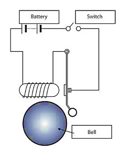
Figure 1: A schematic representation of Door Bell.
Objectives:
- Understand the theory behind the working of Electric Door bell and the electrical components including Solenoid.
- Develop a Simulink model of a doorbell using Solenoid.
- To create a situation where the switch is closed for 2 seconds and then released. Then observation of the physical movement of the plunger.
Simulink Model of Doorbell using Solenoid:
Explanation of the Block set:
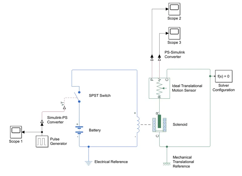
The Pulse Generator block is used to create the square wave pulses. The pulse width and period are set such that the electric switched on for 2 seconds, then closed for 2 seconds and so on. In order to visualize it properly, Scope is fixed at the output of the Pulse Generator. The Simulink-PS Converter converts this Simulink input signal (square wave) into the physical signal so as to close and open the switch. SPST Switch (Single-pole-single-throw Switch) is the switch used where it is controlled by an external control signal vT. If the vT is greater than the threshold, the switch is closed, else the switch is open. The blue diagram in the block set represents the electrical circuit. Battery is the electrical energy source for the electrical circuit. The electrical circuit contains Solenoid which is responsible for the motion of metal arm that is responsible for making the bell sound. For the electrical circuit, Electrical Reference is provided for grounding all the electrical blocks. The mechanical circuit is represented in green color. Both the electrical and mechanical circuit is linked each other with the solenoid. The motion in mechanical arm in solenoid is detected using the Ideal Translational Motion Sensor. It measures the variable and converts it into control signal proportional to velocity and position represented with V and P in the block. For its reference, Mechanical Translational Reference block is used for all mechanical translational ports. The Solver Configuration specifies the solver parameters that the model needs before one can begin the simulation. The variations of position and velocity detected by the Ideal Motion Translational Sensor is displayed using the Scope 2 for Position and Scope 3 for velocity. But the signal from the Ideal Translational Motion Sensor needs to be converted into Simulink signal from the physical signal using the PS-Simulink Converter.
Output and Explanation of the Block set:
In the developed block system, the Pulse generator creates an input signal of amplitude 1 unit at each 4 seconds. Since the 50% pulse width is provided, the switch will be open for 2 seconds, then close for 2 seconds and so on. This can be viewed from Scope 1 as shown in Figure 2.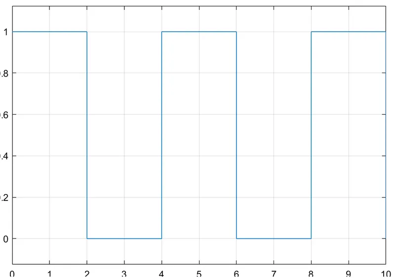
Figure 2: Pulse value with time (s).
This input Simulink signal is converted into physical form by Simulink-PS Converter, and it sent to the SPST Switch. The Switch receives this physical signal and compares it with the threshold value. If the input signal is greater than threshold value, the electrical circuit is closed. Or else, the circuit will remain open. When the Switch is closed, the current from the Battery can flow through the circuit and it will energize the Solenoid. The magnetic field produced by the solenoid will pulls the port R towards C, where this collision is responsible for making ringing sound. The mechanical translational reference is connected to the port C of the solenoid where its sensor can understand the position and velocity of port R with respect to port C. To understand the position and velocity of metallic arm of the solenoid, it is connected with Scope after converting the signal from physical form to Simulink form. The position of the metallic arm and its velocity with time can be seen in Figure 3 and 4.
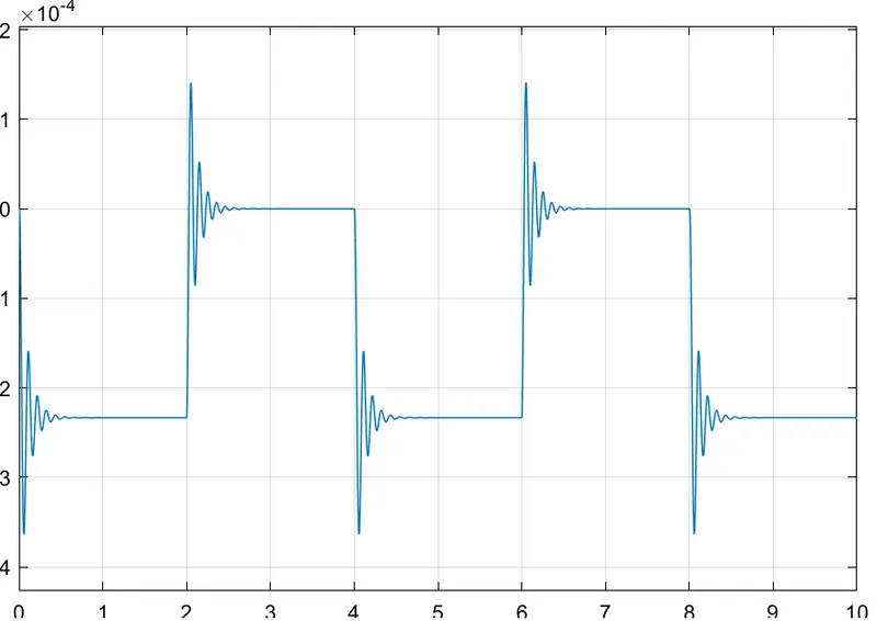
Figure 3: Position of metallic arm of Solenoid with time.
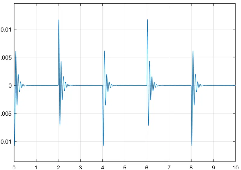
Figure 4: Velocity of metallic arm of Solenoid with time.
Conclusion:
A Simulink model of Doorbell using solenoid block is made successfully and a situation is created where the switch is closed for 2 seconds and then released. The observation of the physical movement of the plunger is also done successfully.
References:
[1] https://www.tlxtech.com/articles/solenoid-101-what-is-a-solenoid
[2] https://www.mathworks.com/help/physmod/simscape/ug/solenoid.html
[3] https://www.mathworks.com/help/physmod/sps/ref/solenoid.html