Simulation of Electro-Mechanical Doorbell and Thermistor-Monitored Heating System
INTRODUCTION:
It is quite common to notice a doorbell in action, typically in schools, colleges and inside almost every house. The purpose of a doorbell is to alert the person(s) about a time constraint, event or if someone is waiting outside the house. As a first part to this project, a doorbell is modeled in Simulink. As part of the modeling, the working principle and components of a doorbell are studied. In the second part of the project, a controlled temperature source in combination with a thermistor is used to monitor a temperature of a room. This is similar to an air-conditioner which is used to control the temperature of a given space (eg. A room). Based on the temperature of the room, the heater triggers a fan to turn on/off to maintain the room temperature at a preset value. The entire heating system is modeled in Simulink along with a thermistor, resistor and other components.
AIM:
The aim of this project is a two-fold as given below:
1.To model a doorbell using a solenoid available in Simulink/Simscape and study the response of the plunger.
2.To model a heater system monitored by a thermistor and switch on/off a fan based on the provided temperature threshold.
OBJECTIVES:
The main objectives of this project include (i) understanding the function of an electro-mechanical doorbell and study the plunger response (ii) to understand the working of a thermistor monitored heating system which turns a DC motor-driven fan on/off depending on the temperature threshold (iii) to use the knowledge gained to build more complex Simulink models
SIMULINK MODEL DESCRIPTION:
(a) Electro-mechanical doorbell:
The Simulink model for the Electro-mechanical doorbell is shown in Figure-1. The input signal is provided using a pulse generator. The signal is of square wave type with an amplitude of 1V and period of 4 seconds and a time-delay of 2 seconds between the two signals. The model is simulated for a total time of 10 seconds. In the next part of the model, a DC output battery is used to power the solenoid electromagnet which moves the plunger towards the common port. In reality, the plunger is the metal arm that hits the bell cap to produce the belling sound. The function of the SPST switch is to close the circuit based on the input signal. An electrical reference block is connected to the negative terminal of the solenoid electromagnet. The Electrical Reference represents an electrical ground connection. It should be noted here that any model with electrical elements must contain at least one Electrical Reference block [1]. The Simulink-to-PS converter changes the signal type from a Simulink signal to a Physical signal. This is required when the block input requires a physical signal. On the other hand, a PS-to-Simulink converter is used to convert a Physical signal to Simulink signal.
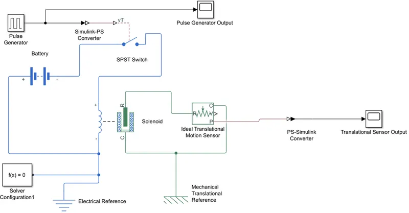
Figure 1 – Simulink model of Electro-mechanical doorbell
An ideal translational motion sensor is connected to the movable plunger in order to record the displacement in ‘m’. This output is displayed using the Scope block.
The link to the Simulink model of an Electro-mechanical doorbell is provided below.
https://drive.google.com/file/d/1_L0ku8EHk0VbRgOguYYbjVg_NitvCibt/view?usp=sharing
Switch ON condition: When the input signal has a non-zero value, current flows through the solenoid electromagnet, moving the plunger. The movement of the plunger is tracked by the translational motion sensor.
Switch OFF condition: If the input signal is zero, no current flows through the solenoid electromagnet and therefore no movement of plunger.
(b) Thermistor-monitored Heating System:
The Simulink model for a Thermistor-monitored Heating System is shown in Figure-2. The input signal is provided using a signal builder block. This provides the temperature input to the controlled temperature source. A thermal reference block is attached to the ‘A’ port of the temperature source. This sets the reference temperature (0K) in the system. After the temperature source, the signal passes to a thermistor which changes resistance based on the temperature field that it is exposed to. The corresponding voltage difference is captured using a voltmeter and a display block. In addition, a resistor (resistance = 1 ohm) is connected in series with the thermistor to observe the voltage drop across the two resistors. The voltage drop across the resistor is used as a threshold to turn on/off a DC motor via a threshold switch. It should be noted here that measured temperature has a relation with the thermistor voltage drop and hence the need for a threshold switch. Apart from the switch output, a Simulink-to-PS converter is connected to the end of the switch, which in turn in connected to the Controlled voltage source.
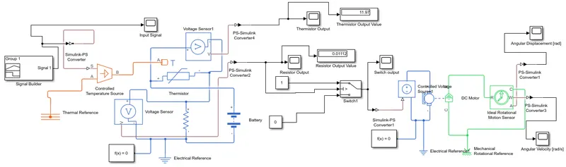
Figure 2 – Simulink model of Thermistor-monitored Heating System
The link to the Simulink model of a Thermistor-monitored Heating System is provided below.
https://drive.google.com/file/d/1LS_ctU5cice7nPrBTf-BBtrV9C_T6aCr/view?usp=sharing
The main advantage of this system is that the DC motor (which in reality is a cooling fan) turns on only when the temperature increases beyond a certain threshold. This is very similar to how an air-conditioner operates. In the last part of the circuit, an ideal rotational motion sensor is connected to the ‘R’ port to measure the angular displacement (in rad) and angular velocity (in rad/sec). A mechanical rotational reference is connected to the common port of the rotational motion sensor to provide a datum for measurement. It should be noted here that the output signal from the rotational motion sensor needs to be converted to a Simulink equivalent signal before plotting the results.
RESULTS AND DISCUSSION:
(a) Electro-mechanical doorbell:
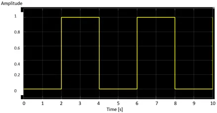
Figure 3 – Pulse generator output for Electro-mechanical doorbell
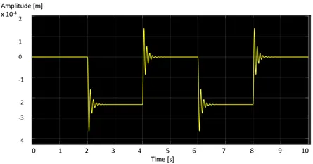
Figure 4 – Plunger displacement for Electro-mechanical doorbell
The results for the doorbell model are shown in Figures 3 and 4. As seen in Fig. 3, the input signal is a square wave which has a time period of 4 seconds and a time delay of 2 seconds. There is no phase delay in the signal. The amplitude is set to 1V. The displacement of the plunger is shown in Fig. 4. It is noted from Fig. 4 that at every 2 second intervals, the displacement amplitude experiences a 3.5 x 10⁻⁴ m (relative) change in the value approximately. After that, the response decays with time with an average decay time of 0.5 seconds (approximately).
(b) Thermistor-monitored Heating System:
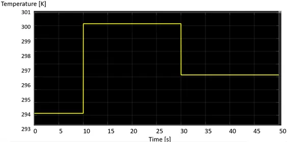
Figure 5 - Temperature input to the controlled temperature source
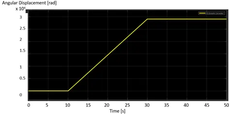
Figure 6 - Angular displacement of the DC motor (Fan)
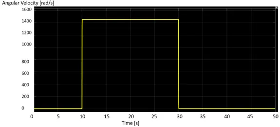
Figure 7 - Angular velocity of the DC motor (Fan)
The results for the Thermistor-monitored Heating System model are shown in Figures 5-7. In Fig. 5, the input signal from the controlled temperature source is presented. It can be observed that the temperature input is constant over a preset range of time and changes to a different value after that. The temperature inputs provided in the model are according to the problem statement. The temperature distribution is given as follows:
|
Temperature [°C] |
Temperature [K] |
Time Duration [s] |
|
20 |
293.15 |
0-10 |
|
27 |
300.15 |
10-30 |
|
23 |
296.15 |
30-50 |
The angular displacement plot is shown in Fig. 6. Since the fan starts rotating only when the temperature crosses 25°C, the angular displacement remains at zero in the initial part of the plot (i.e. between 0-10 seconds). After 10 seconds, a linear increase in the angular displacement is observed till time = 30seconds. This is the time period during which the fan in turned on as the temperature input is over 25°C. After 30 seconds, the fan rotation stops as the temperature input falls below 25°C and hence the angular displacement remains at the previous value. In the angular velocity distribution illustrated in Fig. 7, it is inferred that the angular velocity is zero till 10 seconds as the temperature remains below 25°C. After 10 seconds there is a step increase in the angular velocity to 1466.66 rad/s (153 rpm) approximately. This increase is attributed to the difference in temperature between the threshold value (25°C) and the actual temperature (27°C). This results in the operation of the fan to maintain the temperature at 25°C. After 30 seconds, the temperature once again falls below 25°C and hence the fan is turned off. Therefore the angular velocity return to zero again.
CONCLUSIONS:
In this project, a detailed study of an electro-mechanical doorbell and a thermistor-monitored heating system was undertaken. The systems were modeled in Simulink with multiple blocks (from Simulink and Simscape). The simulation results provided deep understanding of the underlying physics of the aforementioned systems. As a future effort, one can look into a thermistor-monitored cooling system which operates in a similar way as the heating system excepting for the temperature threshold. In addition, the heat transfer modes (i.e. conduction, convection, radiation) can be studied with a thermal model in Simulink.
REFERENCES:
- “Matlab R2020b Documentation”, Mathworks Inc.
- “Skill Lync Lecture Videos”, Skill Lync India Pvt. Ltd.