Simulation of Buck converter using Simulink and Spice tool
1- Simulate the designed DC/DC converter in the first challenge using Matlab Simulink . Show the following waveforms from your individual simulation with your comments.
a) Input voltage and current.
b) Output voltage and current.
c) Converter duty ratio and inductor current.
d) Mosfet and diode voltage waveforms.
2- Simulate the same DC/DC converter in a SPICE based simulation tool (e.g.TINA TI) through the following steps:
a) Choose the converter real components (MOSFET, Diode, Inductor, etc…).
b) Show the same platforms of problem 1
c) Compare the results in problem 1 with the results you are getting here and explain the reason for the differences.
Your Answers
Simulation of Buck converter using Simulink and Spice tool:
1- Simulate the designed DC/DC converter in the first challenge using Matlab Simulink. Show the following waveforms from your individual simulation with your comments.
a) Input voltage and current.
b) Output voltage and current.
c) Converter duty ratio and inductor current.
d) Mosfet and diode voltage waveforms.
Circuit Diagram:
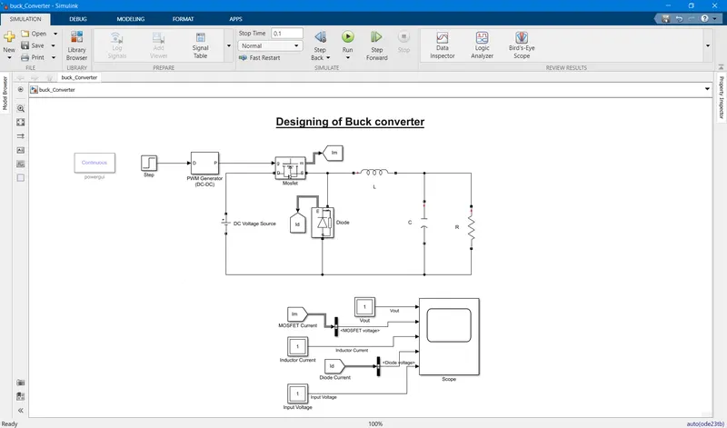
a) Input voltage and current.
Input Voltage: 48V
Input Current: 5A
b) Output voltage and current.
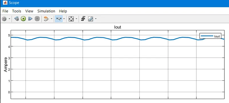
Output Current: ~5A
The current is passing through the Load Resistor.
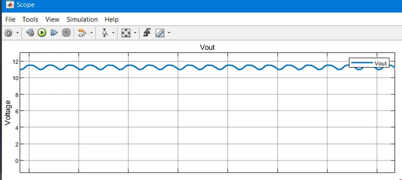
Output Voltage: ~12V
The voltage across the Load Resistor.
c) Converter duty ratio and inductor current.
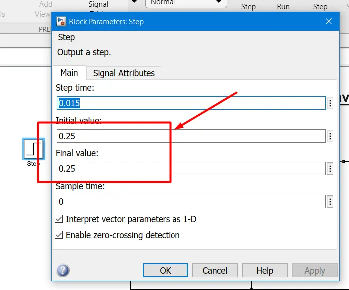
As calculated the Duty Cycle is: Vout/Vin= 0.25
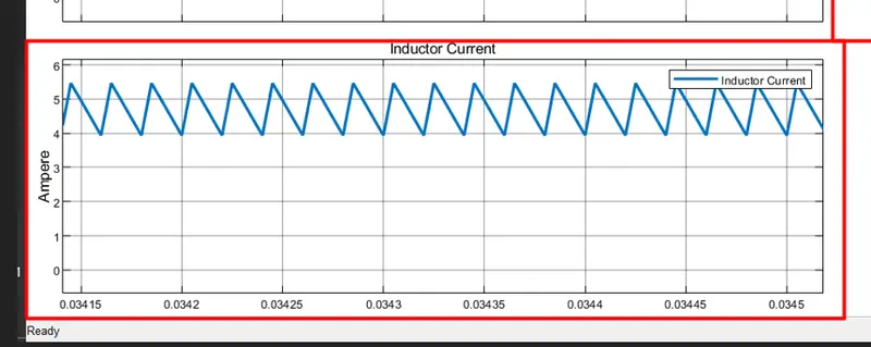
The inductor current must be 5A with the ripple being less than 30% of the average inductor current.
d) Mosfet and diode voltage waveforms.
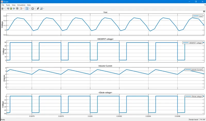
2- Simulate the same DC/DC converter in a SPICE based simulation tool (e.g.TINA TI) through the following steps:
a) Choose the converter real components (MOSFET, Diode, Inductor, etc…).
b) Show the same platforms of problem 1
c) Compare the results in problem 1 with the results you are getting here and explain the reason for the differences.
For TINA TI:
open TINA TI
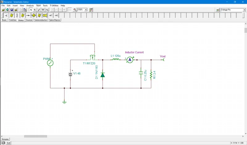
To design a buck converter we need components,
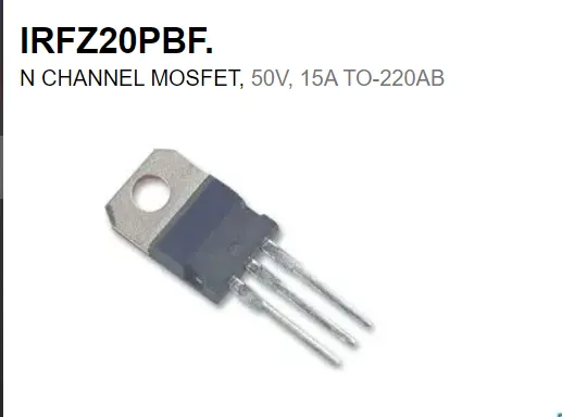
MOSFET: IRFZ20 (Max VDS (V) and current is 50V, 15A)
Diode: 1N1183
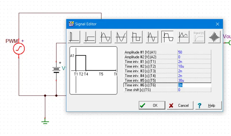
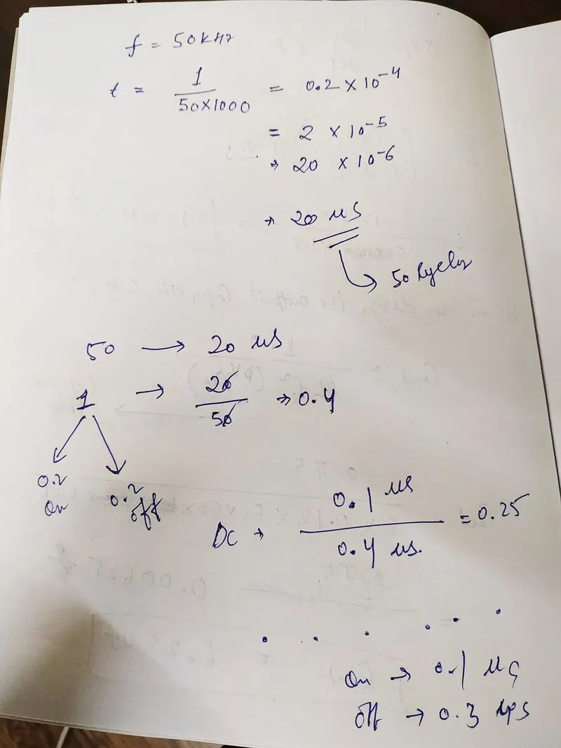
PWM Generator: for Duty Cycle: 0.25 and 50kHz frequency Settings
Circuit Diagram:
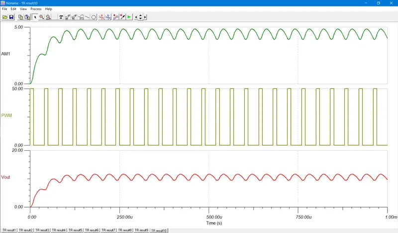
Output:
Comments:
| MATLAB Simulation | TINA TI Simulation |
|
|
|
In MATLAB we do not have to worry about the time period and amplitude of the PWM signal |
But we have to calculate the Time period and design the PWM signal accordingly.
|
|
|
|
Vout= 12V Output Current= 5.5A |
Vout= 11.7V Output Current= 4.7A |
| In MATLAB we are getting the ideal OUTPUT as calculated because in MATLAB we do not need to select practical components. | But in TINA TI we have to specify the practical component name such as IRFZ20 MOSFET, 1N1183 diode, etc so we are getting no ideal condition output or practica condition output |
--------------------------------------------------------------------------------------------------------------------------------------------------------------------------------------------------------------------END--------------------------------------------------------------------------------------------------------------------------------------------------------------------------------------------------------------------------------------