Simulating Fluid Sloshing effect inside a Gear-box
Gearbox Sloshing Effect Analysis
Aim - To simulate Gear Sloshing Effect Analysis.
Introduction
Sloshing
In fluid dynamics, slosh refers to the movement of liquid inside another object (which is, typically, also undergoing motion).
The liquid must have a free Surface to constitute a slosh dynamics problem, where the dynamics of the liquid can interact with the container to alter the system dynamics significantly. Important examples include propellant slosh in spacecraft tanks and rockets (especially upper stages) and the free surface effect (cargo slosh) in ships and trucks transporting liquids (for example oil and gasoline). However, it has become common to refer to liquid motion in a filled tank, i.e. without a free surface, as "fuel slosh".
Such a type of motion can also be seen in a gearbox. In a gearbox, the gears are partially immersed in lubricant in the gearbox, and when the gears get rotated, it takes the oil with it, such that the lubricant reaches all the teeth of the gear. And hence, through the movement of gears, the lubricant gets distributed into the gearbox.
Gearbox
A transmission is a machine in a power transmission system, which provides controlled application of the power. Often the term 5-speed transmission refers simply to the gearbox that uses gears and gear trains to provide speed and torque conversions from a rotating power source to another device.
The most common use is in motor vehicles, where the transmission adapts the output of the internal combustion engine to the drive wheels. Such engines need to operate at a relatively high rotational speed, which is inappropriate for starting, stopping, and slower travel. The transmission reduces the higher engine speed to the slower wheel speed, increasing torque in the process.
Procedure
1. Preparing the geometry
For the simulation, the STEP file of the gearbox having 2 gears has been taken into account.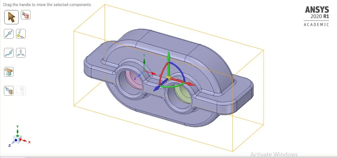
Then, the Volume extract option is used (which is located in Prepare), so that the region in which the lubricant is can be made.
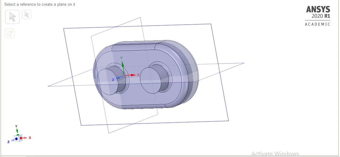
The section view showing the 2 gears being immersed in the lubricant region is shown below.
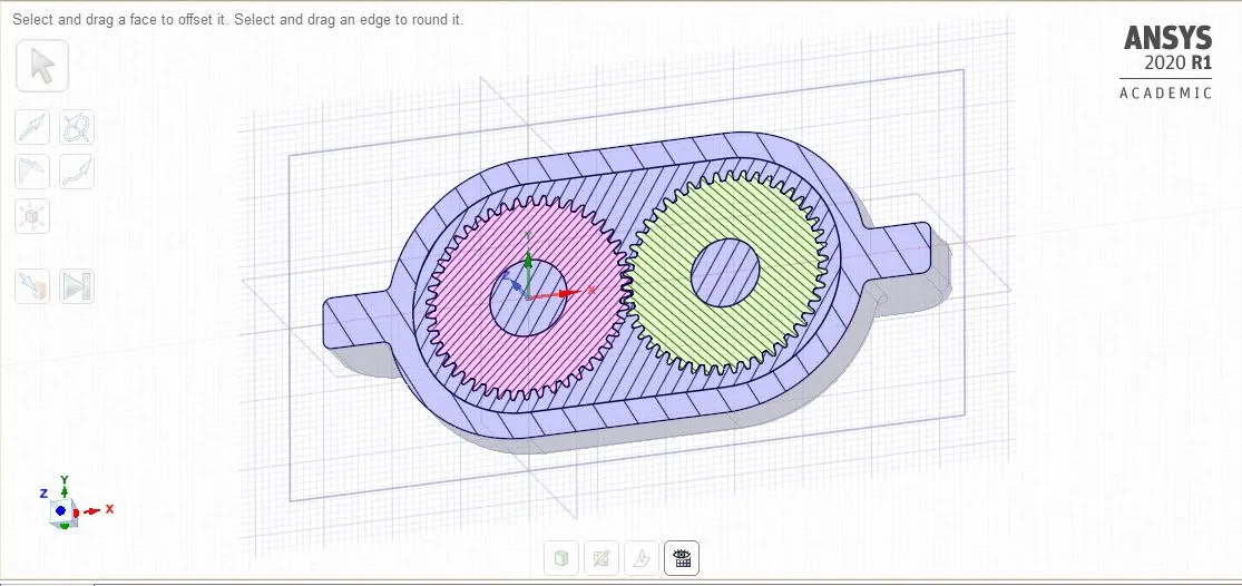
After that, we will split the body in half so that we can copy the section of gears and housing. For pasting them into the new geometry, for doing the 2-D simulation.
For splitting the body, we will use the Split body tool which can be found in Design. First, select the split body tool, after that select the whole body and then the plane through which you want to split it, and the resulting figure will somewhat look like the image shown below.
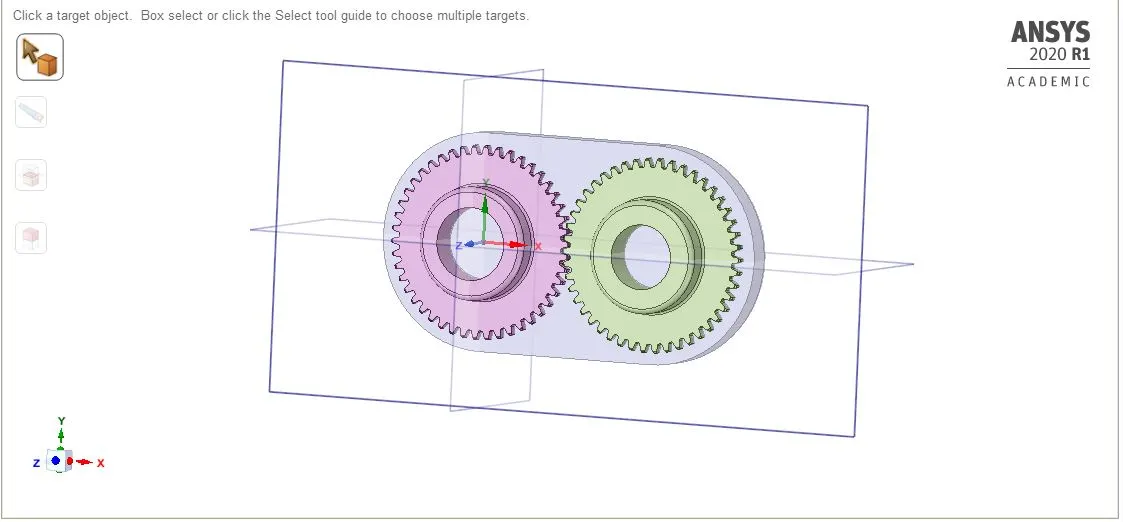
After that, select the region you want to copy, in this case, the outer region of gears, so that the image of gears, as well as the region in which the lubricant will be there, can be seen clearly. And after pasting it to the new geometry, the resulting geometry will somewhat look like the image below.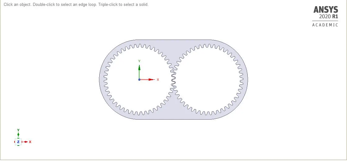
Note - The Y-X plane is chosen for ease in the calculation.
Now close the geometry and move for meshing.
3. Meshing
As the geometry gets uploaded. The following settings are been used.
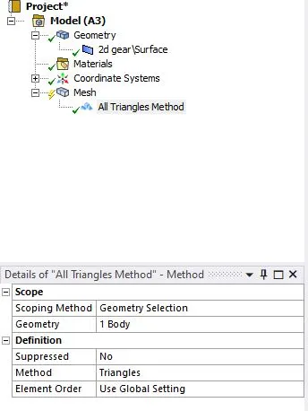
The mesh size is taken to be 2mm and in the sizing option, the Capture proximity is turned "yes" and the number of cells across gaps to be 1.
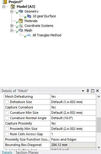
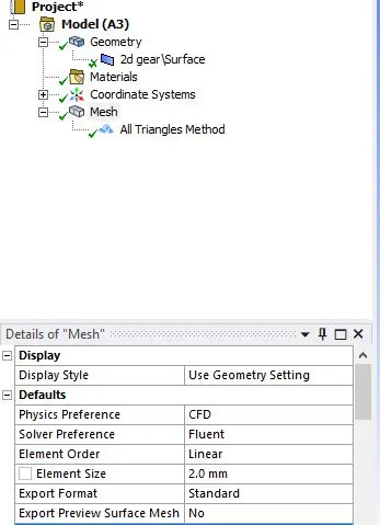
After the options are applied, the resulting mesh will look like the image shown below.
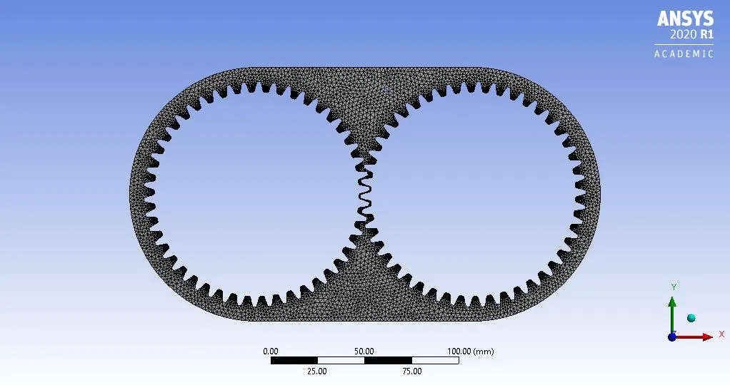
Once the meshing is done. Select the gear teeth of the right gear and name it as Right_Gear. Do the same for the left gear as well. And once these things are done, the meshing is complete.
4. Setup
For setup, we will be using Double-precision with 4 Processors.
Once the Ansys fluent is loaded, perform a mesh check so that you can see that the mesh has been properly generated. Once the mesh is checked the message in the console will show. After checking the mesh, The first thing you need to do is to set up the general settings. Which, the following settings have to be done.
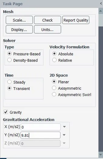
Once the general settings are done, we will move to setting up the physics. In this, first, we will add the material which will be having 2 cases.
Case 1. We will be adding engine oil.
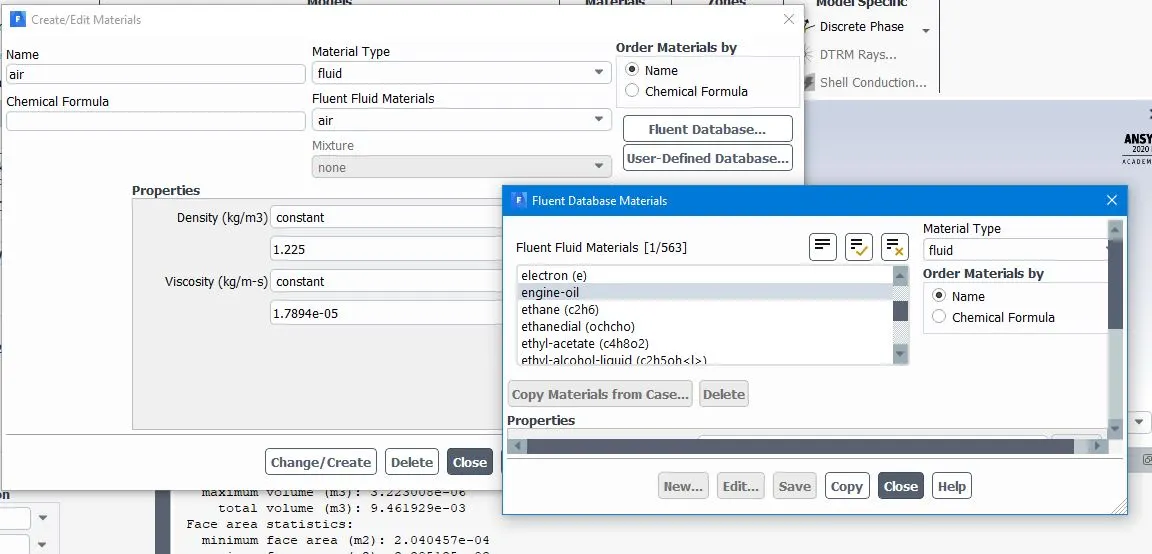
Case 2. We will be adding n-heptane.
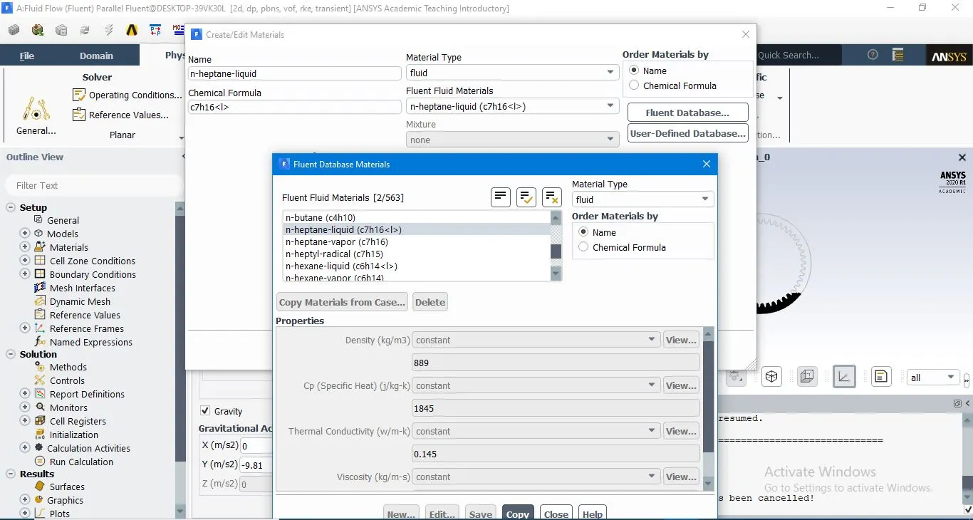
Now, for both cases. We need to set up the viscous model whose settings will be shown below.
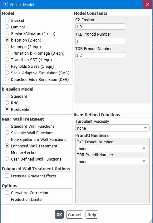
After the Viscous model is set up, we need to set up the Multiphase Model whose settings are as shown below.
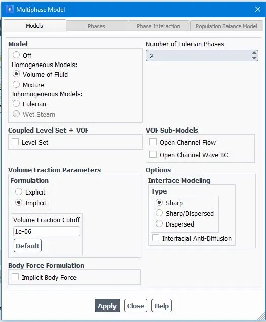
Now moving forward, we have to study each case.
Case 1: We will be using engine oil as a lubricant. We need to set up the primary phase and secondary phase as shown below.
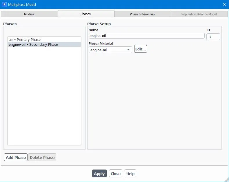
Once this is done, we need to set the region of coordinates to mark the height to which the lubricant will be there.
Part 1. - When the lubricant is at 20% Immersion.
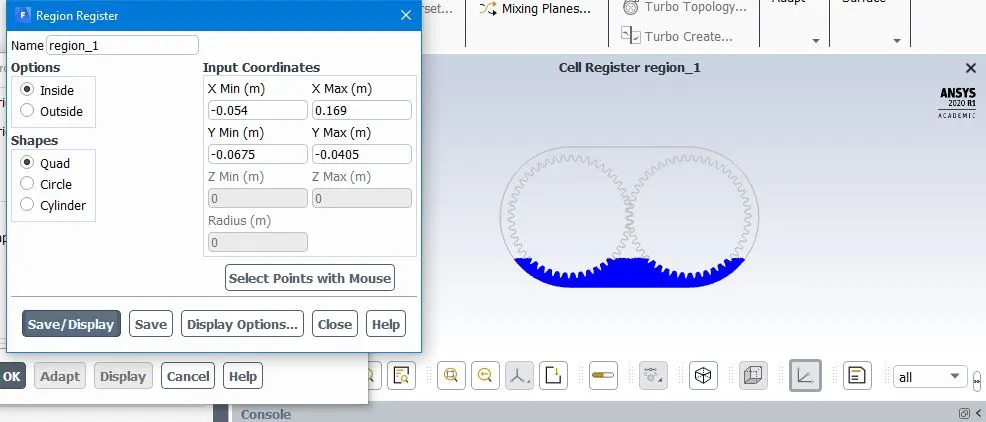
After that, we need to upload the UDF file.
Part 2 - When the gears are at 30% Immersion.
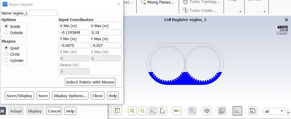
After that, we need to upload the UDF file.
Case 2: We will be using n-heptane as a lubricant. We need to set up the primary phase and secondary phase as shown below.
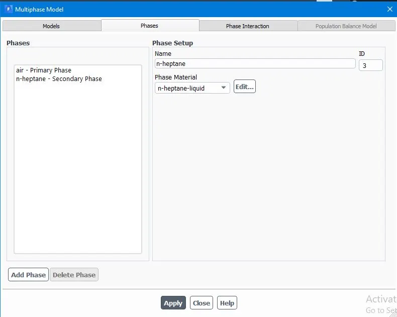
Once this is done, we need to set the region of coordinates to mark the height to which the lubricant will be there. Since the immersion height is the same as 20% and 30% as in the previous case. The settings for the mark and coordinates for the region will remain the same.
5. Simulation
The simulation was then done for the 2 cases was done. The Solution animation is given below
Case 1.1-20% Immersion, Fluid - Engine oil.
Solution animation link-https://drive.google.com/file/d/1_BQ85uDsEXTLmlGJpV1mHRGDV53B4iJs/view?usp=sharing
Case 1.2-30% Immersion, Fluid- Engine oil
Solution animation link-https://drive.google.com/file/d/1Pgnj_iEyPDv9kM5NO4t1Sv8MDXnf9ZgQ/view?usp=sharing
Case 2.1-20% Immersion, Fluid- n-heptane (c7h16).
Solution animation link-https://drive.google.com/file/d/1F2j4-bcp2opUn7sX5DKcun3U6jpZAa3A/view?usp=sharing
Case 2.2-30% Immersion, Fluid- n-heptane (c7h16).
Solution animation link- https://drive.google.com/file/d/1xhtuPcdippbITUIG73hXC38JONX9e3zM/view?usp=sharing
Appendix
1.)What is Dynamic meshing? Give some other examples where dynamic meshing can be used.
In ANSYS Fluent the dynamic mesh capability is used to simulate problems with boundary motion, such as check valves and store separations. The building blocks for dynamic mesh capabilities within ANSYS Fluent are three dynamic mesh schemes, namely, smoothing, layering, and remeshing. A combination of these three schemes is used to tackle the most challenging dynamic mesh problems. However, for simple dynamic mesh problems involving linear boundary motion, the layering scheme is often sufficient. For example, flow around a check valve can be simulated using only the layering scheme. Check valves are commonly used to allow unidirectional flow. For instance, they are often used to act as a pressure-relieving device by only allowing fluid to leave the domain when the pressure is higher than a certain level.
2.)What is the use of UDF?
A user-defined function (UDF) is a function provided by the user of a program or environment, in a context where the usual assumption is that functions are built into the program or environment.UDF allows customizing Ansys fluent to fit particular modeling needs.UDF can be used for several applications like :
1. Customize boundary conditions
2. Material property definitions
3. Adjust computed values on a once-per-iteration basis
4. Initialize with a previous solution
5. Execute at the end of an iteration
6. Upon exit from ANSYS FLUENT
7. Enhance post-processing
8. Enhance existing ANSYS FLUENT models (such as discrete phase model, multiphase mixture model, discrete ordinates radiation model)
3.) Discuss the common errors that occurred in the simulation. A] 'Dynamic mesh failed' error. B] 'Negative cell volume detected' error.
Before adjusting the values in the dynamic meshing the failure of Dynamic mesh error and negative cell volume detection error are caused. This is caused as the gear rotates the meshed around them also encounters a change which leads to breakage in the mesh connection. This causes the formation of negative cell volumes.