Conjugate Heat Transfer Analysis on a graphics card.
Conjugate Heat Transfer Analysis on a graphics card
Aim- To Simulate an CHT analysis on a graphic card
Introduction
Conjugate heat transfer corresponds with the combination of heat transfer in solids and heat transfer in fluids. In solids, conduction often dominates whereas in fluids, convection usually dominates. Conjugate heat transfer is observed in many situations. For example, heat sinks are optimized to combine heat transfer by conduction in the heat sink with the convection in the surrounding fluid. In the given problem a heat sink is attached to a graphic card and air is flowing over the graphic card. CHT analysis is done to analysis the Heat transfer cofficient at various speed to air flowing over the graphic card.
Procedure
1). Preparing the geometry
The step file of the graphic card was loaded on spaceclaim. An enclosure was created over the Graphic card by using the "Enclosure" function in the "Prepare" section of spaceclaim. After that a check on interference was done.The topology was set to "share" and in "workbench" section, "share" function was used to get an conformal mesh.
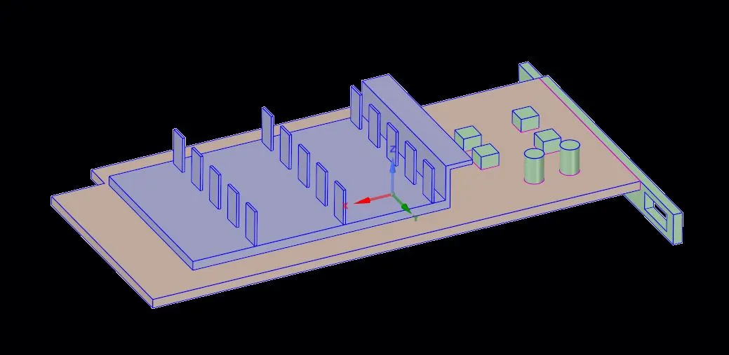
1.Image of the Graphic Card
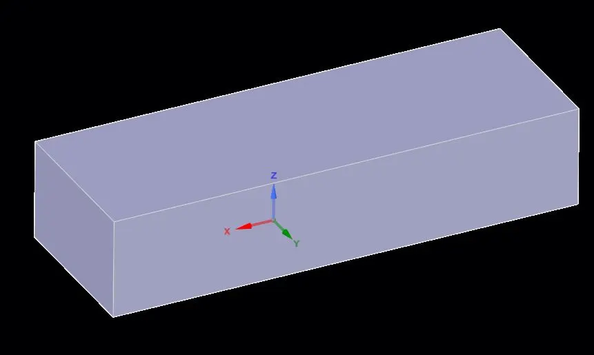
2. Image of enclosure around the Graphic Card
2.) Meshing
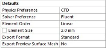
After preparing the geometry, the Meshing module was opened. Inlet, outlet, heat sink and other section of the geometry were named. Then a default mesh was generated.The information about the default mesh is given below.
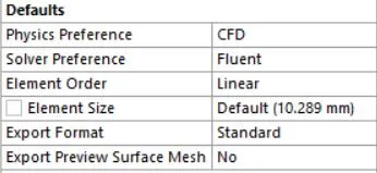

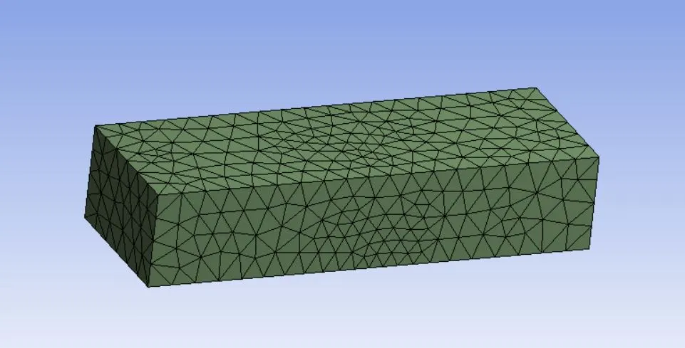
3. Image of the default mesh
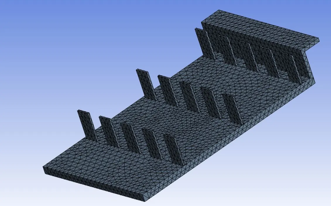
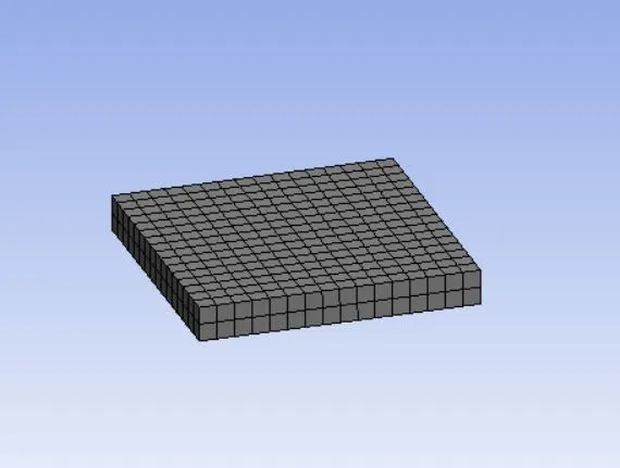
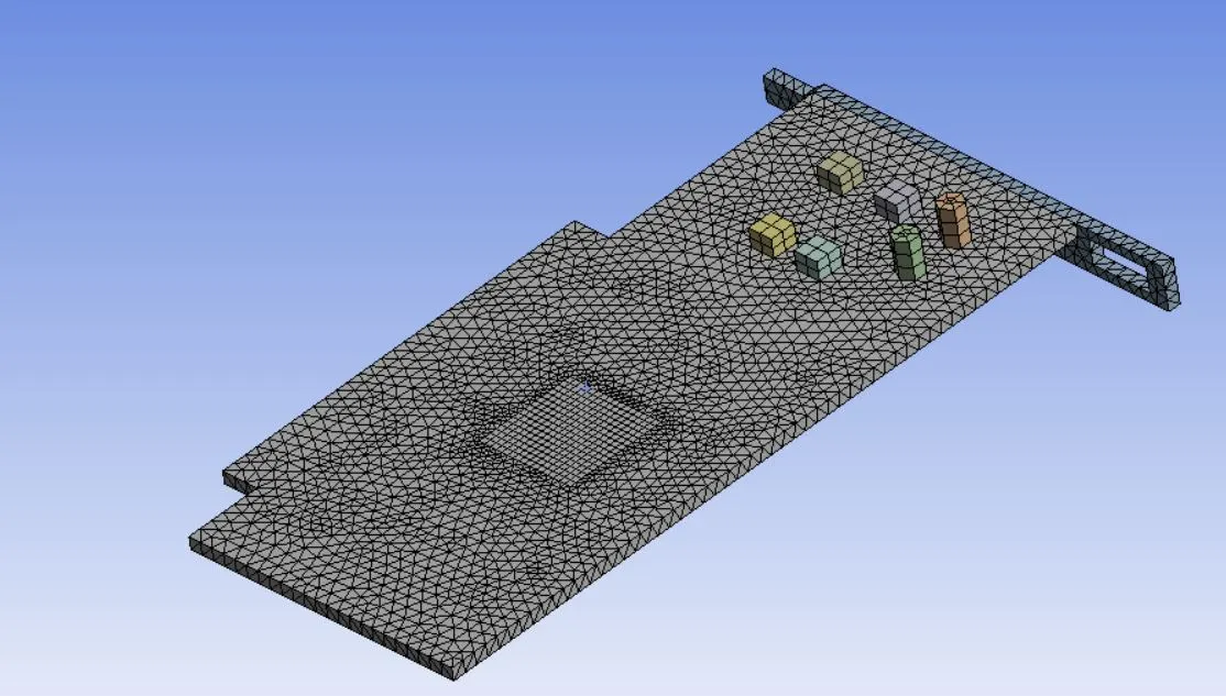
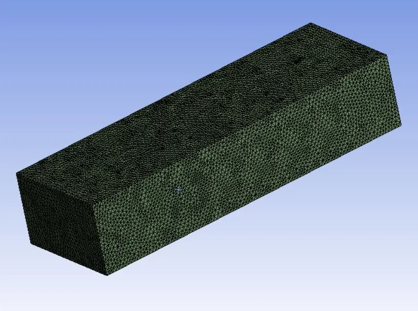
After generating a default mesh a refined mesh was generated. The element size was set to 2mm. "Sizing" tool was used to generate mesh of desired size of various body like Heat sink and Graphic card.
1. Heat sink
Element size- 0.75mm
2. Graphic Card
Element size- 0.25mm
3. PCB Board
Element size - 1mm
4. Enclosure


3. Simulation
For the simulation fluent was opened. The Simulation was done at 3 speeds (1 m/s,2.5m/s,5m/s respectively)of air flowing over the graphic card at 298K. In all the 3 simulations a pressure based solver is used. For turbulance model, realizable k-epsilon with standard wall function is used. The working fluid is air and the material for heat sink processor and PCB board are aluminium,gold and copper respestively with default mechanical properties. The power rating of the grahic card is assumed as 20W. Therefore the heat genetation rate is -
Heat generation rate= 20/(6.4`times``10^-9`)=312500000 W/`m^3`
Assuming the dimensions of the grahpic card are `8xx8xx1`mm
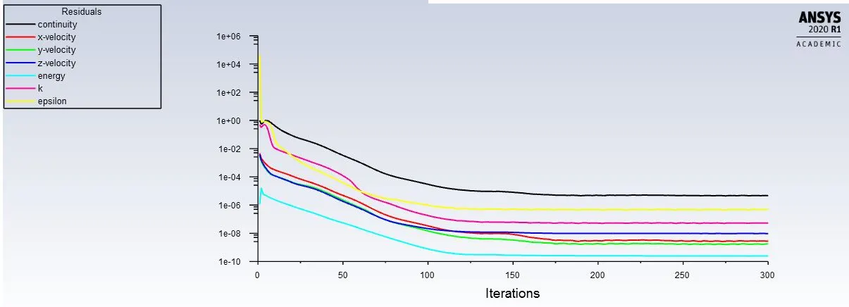
The simulation were done for 300 iterations
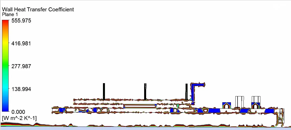
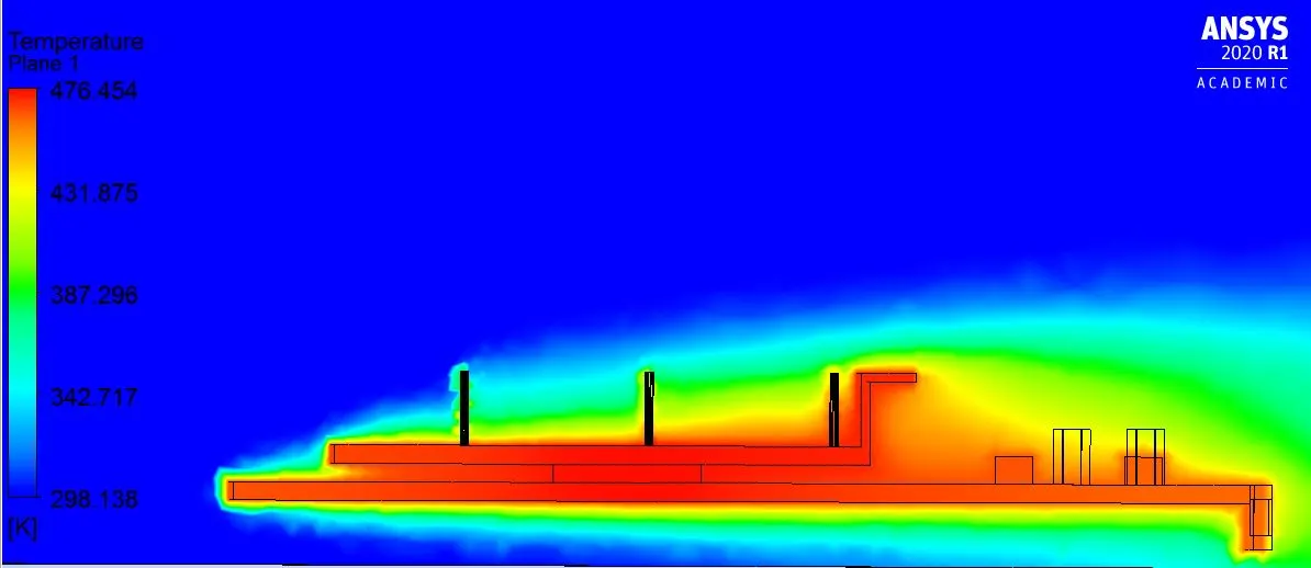
Case 1- Speed of air flow at 1m/s
The solution converged around 120 iterations
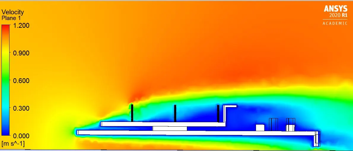
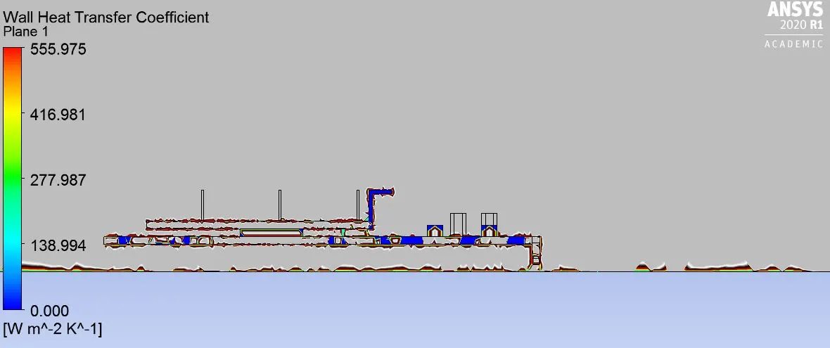
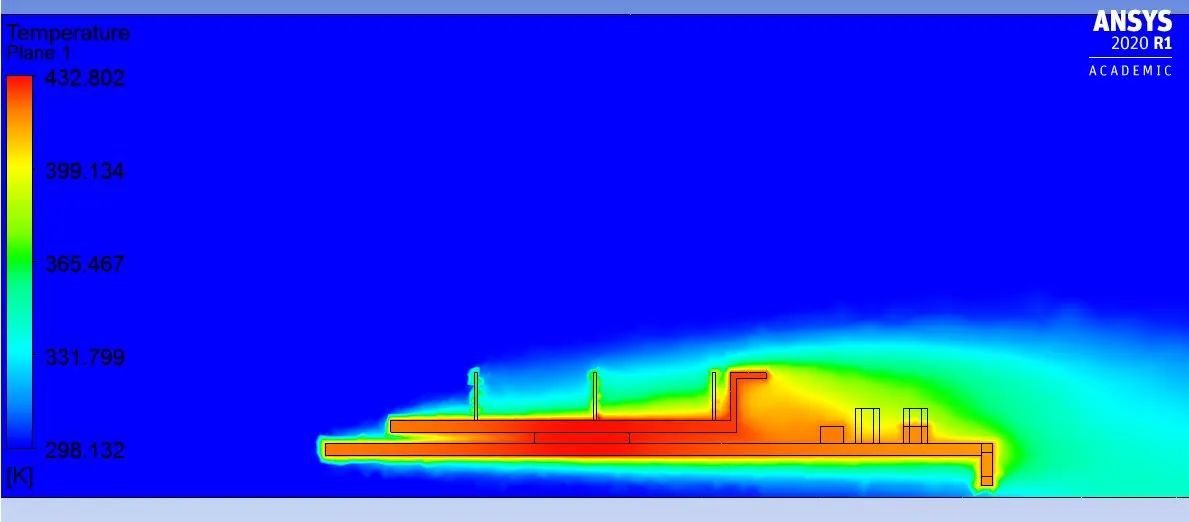
Case 2- speed of air is 2.5 m/s
The solution converged around 100 iterations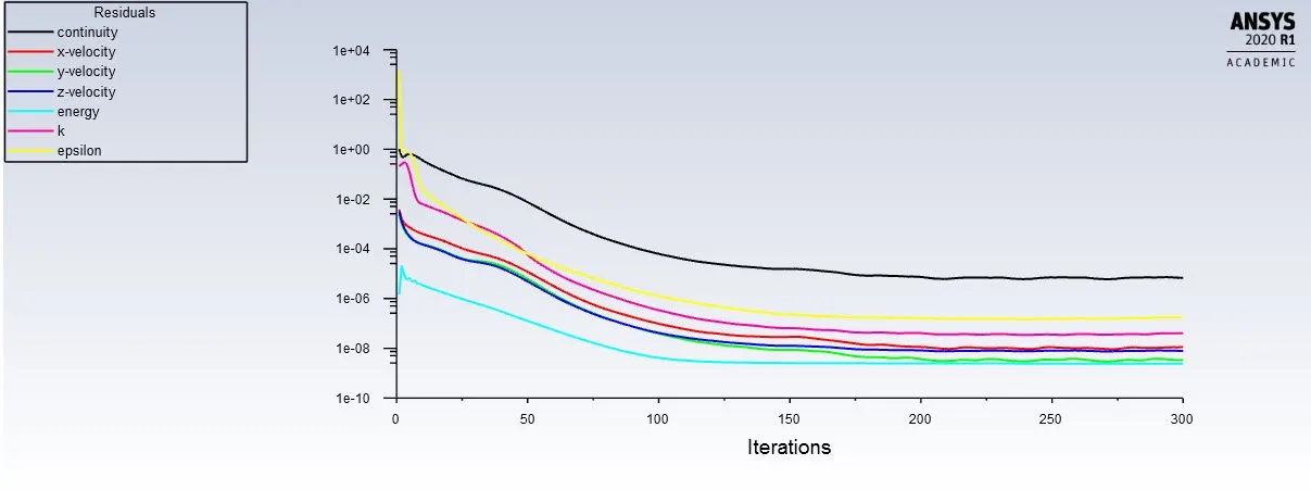
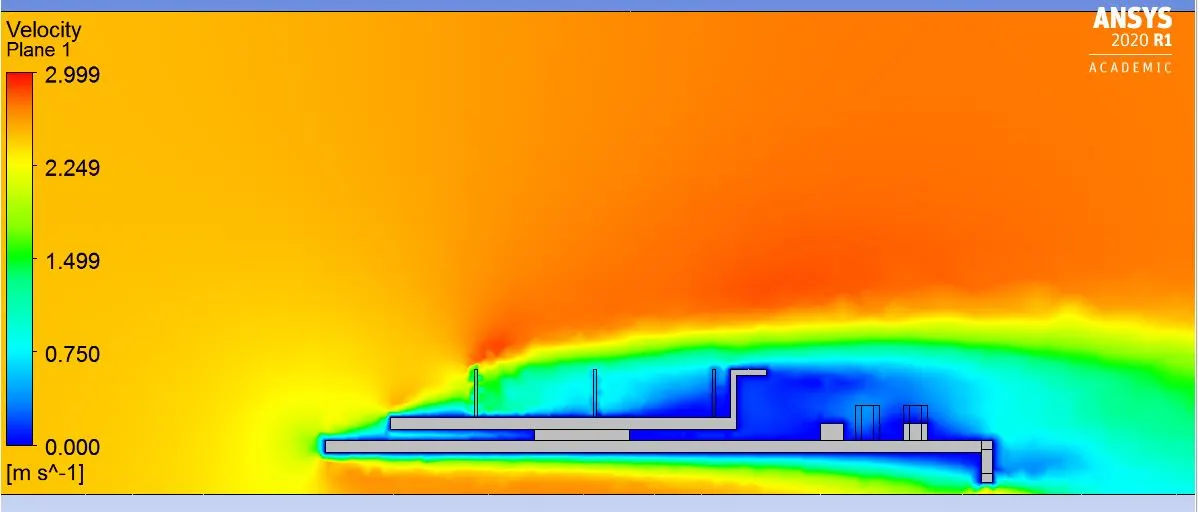
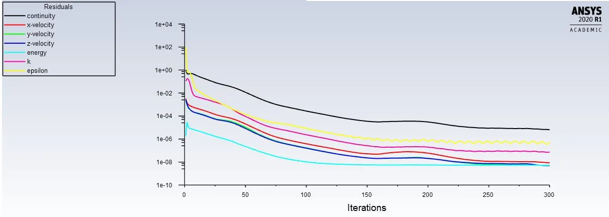
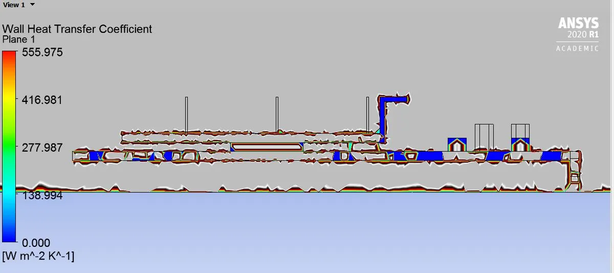
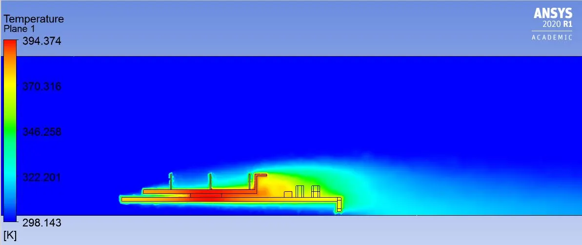
Case 1- Speed of air flow at 5m/s
The solution converged around 100 iterations
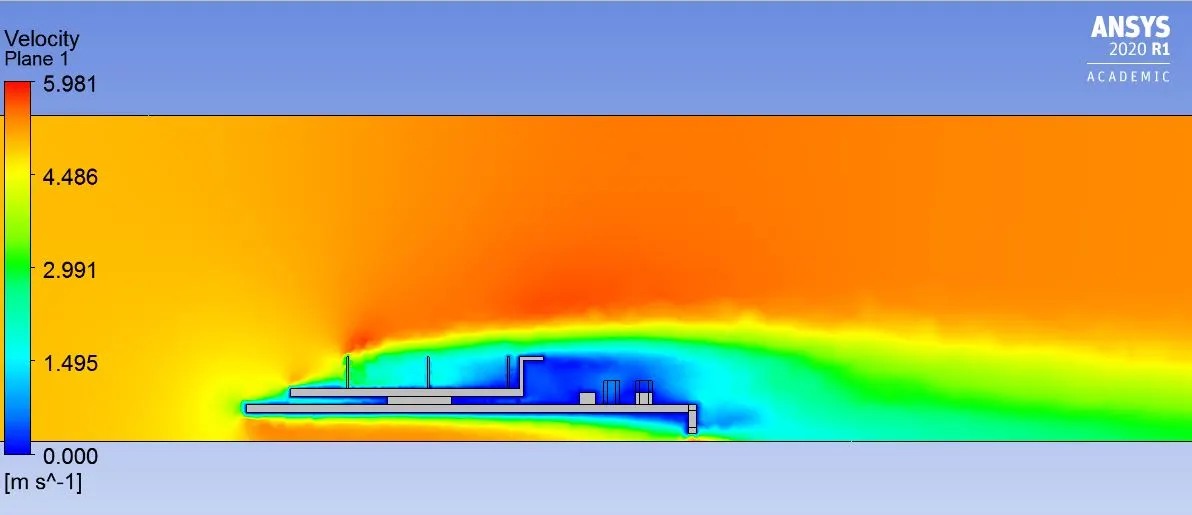
4.) Conclusion
As the velocity is increased, the temperature of the graphics card has descreased. The mesh plays an important role is observing the temperature of the graphics card.
| CASE | VELOCITY OF AIR(m/s) | Wall HTC (W/`m^2K`) | MAX. TEMPERATURE (K) |
| 1 | 1 m/s | 555.975 | 476.454 |
| 2 | 2.5 m/s | 555.975 | 432.801 |
| 3 | 5 m/s | 555.975 | 394.374 |