Simulation of shock produced in a shock tube using Converge CFD
Aim:
To set up a shock tube with a high-pressure differential between the two regions (low and high-pressure region filled with O2 and N2 gas respectively) and simulate the formation of shocks as a result of rupture of the diaphragm that separates these two regions from each other.
Theory:
The shock tube is an instrument used to replicate and direct blast waves at a sensor or a model in order to simulate actual explosions and their effects, usually on a smaller scale. Shock tubes (and related impulse facilities such as shock tunnels, expansion tubes, and expansion tunnels) can also be used to study aerodynamic flow under a wide range of temperatures and pressures that are difficult to obtain in other types of testing facilities. Shock tubes are also used to investigate compressible flow phenomena and gas-phase combustion reactions. More recently, shock tubes have been used in biomedical research to study how biological specimens are affected by blast waves.
In addition to measurements of rates of chemical kinetics shock tubes have been used to measure dissociation energies and molecular relaxation rates they have been used in aerodynamic tests. The fluid flow in the driven gas can be used much as a wind tunnel, allowing higher temperatures and pressures therein replicating conditions in the turbine sections of jet engines. However, test times are limited to a few milliseconds, either by the arrival of the contact surface or the reflected shock wave. They have been further developed into shock tunnels, with an added nozzle and dump tank. The resultant high-temperature hypersonic flow can be used to simulate atmospheric re-entry of spacecraft or hypersonic craft, again with limited testing times.
Shock tubes have been developed in a wide range of sizes. The size and method of producing the shock wave determine the peak and duration of the pressure wave it produces. Thus, shock tubes can be used as a tool used to both create and direct blast waves at a sensor or an object in order to imitate actual explosions and the damage that they cause on a smaller scale, provided that such explosions do not involve elevated temperatures and shrapnel or flying debris. Results from shock tube experiments can be used to develop and validate numerical models of the response of a material or object to an ambient blast wave without shrapnel or flying debris. Shock tubes can be used to experimentally determine which materials and designs would be best suited to the job of attenuating ambient blast waves without shrapnel or flying debris. The results can then be incorporated into designs to protect structures and people that might be exposed to an ambient blast wave without shrapnel or flying debris. Shock tubes are also used in biomedical research to find out how biological tissues are affected by blast waves.
Geometry:
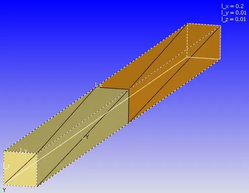
The length of the entire shock tube (x-direction) is 0.2m, the length of the high-pressure and low-pressure region is 0.1m. The width and height of the tube are 0.01m.
Case setup:
1. Mesh size
0.002m in all three coordinate axes.
2. Simulation parameters:
Solver= Transient-state solver
Simulation mode= Full hydrodynamic
Gas flow solver= Compressible
3. Simulation time parameters:
Start time= 0.0s
End time= 0.003s
Initial time-step= 1e-7s
Minimum time-step= 1e-7
Maximum time-step= 1e-5
Maximum convection CFL limit= 0.5
4. Solver parameters:
Navier-Stokes solver scheme= PISO
Navier-Stokes solver type= density-based
5. Regions and Initialization
a) High-pressure region
Species= N2
Pressure= 600000 Pa
a) Low-pressure region
Species= O2
Pressure= 101325 Pa
6. Events:
Events described below are between regions
a) Event= Close (0-0.001s)
b) Event= Open (0.001-0.003s)
7. Boundary:
Two boundaries defined
a) High-pressure boundary (Region assigned= High-pressure region)
b) Low-pressure boundary (Region assigned= Low-pressure region)
Both the boundaries are provided with the stationary wall, slip boundary condition
8. Turbulence model:
RNG K-epsilon turbulence model
9. Adaptive mesh refinement:
Active regions= high-pressure region, low-pressure region
AMR by species N2
Timing type= Permanent
SGS embed= 0.001
Start and end time= 0-0.003s
Embed scale= 3
Results:
Mesh:
Pressure:
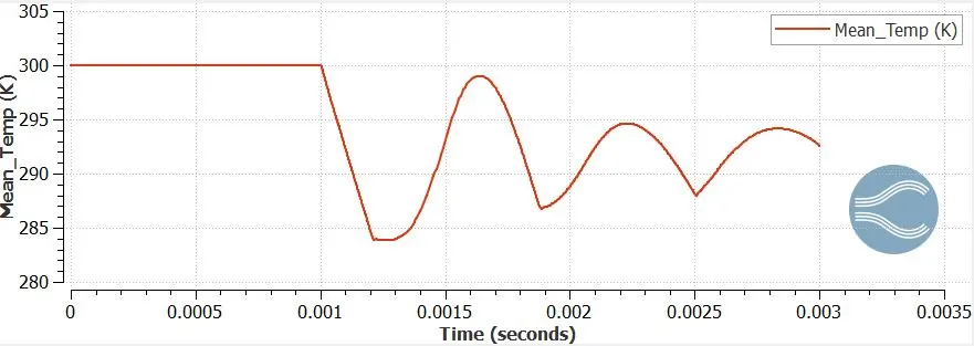
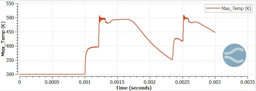
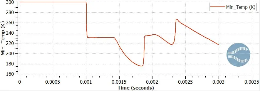
Temperature:
Species:
Density contours:
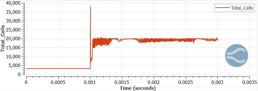
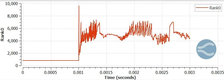
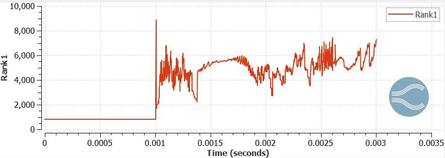
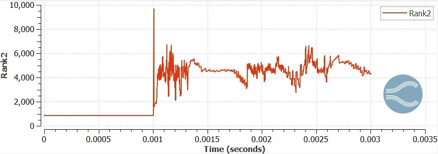
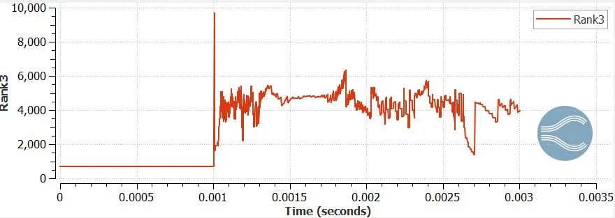
Cell count:
Conclusions:
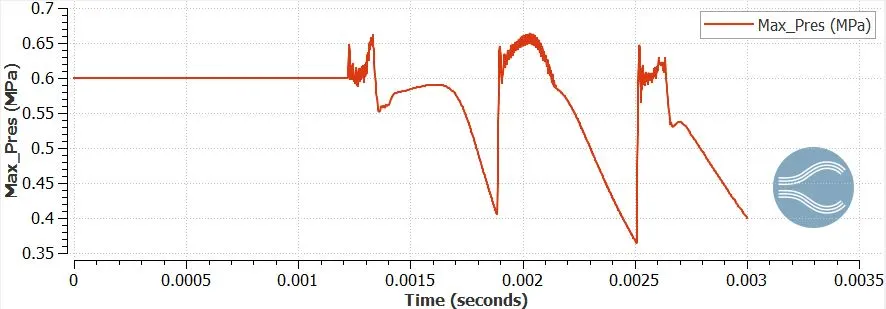
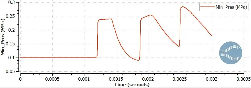
- As the diaphragm ruptures, shock waves are produced as a result of the pressure difference between the 2 regions. These shock waves influence the behavior of fluid properties within the system.
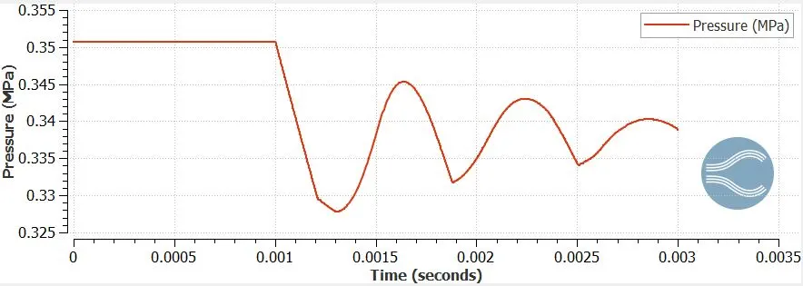
- The average pressure of the system tends to converge to a particular value after a certain time after the rupture of the diaphragm. But this is not before the mean pressure profile follows a damping oscillatory path. The oscillations are caused due to the shock waves hitting the walls of the domain, which causes an increase in the pressure. This magnitude of pressure keeps decreasing with the number of times it hits the walls, until it eventually dies out.
- Eventhough, the average temperature of the domain tends to decrease with time as it reaches steady-state, we can clearly observe that as a result of shock waves, the temperature of the gasses increases to ~500K
- As a result of shock waves produced following the rupture of the diaphragm separating the high and low pressure regions, the gasses present in the high and low pressure regions N2 and O2 respectively are not able to mix with each other, and hence the mixing of these gasses will take place completely only after the shock waves have died out.
- The density of the gas present in the high-pressure region (N2) is comparatively higher than that of the gas present in the low-pressure region (O2). Once the diaphragm is ruptured, the mixture tends to converge to a particular value of density, But this is not before the shock waves produce instability of the gas density. The shock waves increase the density of the gas mixture as it passes by. The system will converge to a particular value of density once the shock waves have died out.
- This problem was solved using 4 processors. Since the 'Adaptive Mesh Refinement' option is enabled, and because of the instability of the system post the rupture of the diaphragm wall, there is a spike in the cell count, which has been approximately distributed evenly between the 4 processors. And since this region of instability changes with respect to time, the cell count also changes with respect to time. This is the reason why the cell count changes for almost every single time-step post the diaphragm wall rupture.