Section Modulus calculation and optimization
Aim:
To find the section modulus of the hood and optimization to improve the overall section modulus.
Objective:
Use the section from your Hood design and calculate the section modulus using the formula S= I/y
The objective of this report is to understand section of the model and analyze its effects on BIW structure by optimizing it under different conditions.
Section properties are vital in structural analysis and design which is efficient to increase the load bearing capacity by optimizing the shape of the section. One such property is section Modulus and is explained below.
Section Modulus:
SECTION MODULUS is the ratio of the moment of inertia about neutral axis upon the extreme point of the section from the neutral axis.
The section modulus (S) is geometry property of the cross section used for designing beams and flexural members. It does not represent anything physically.
Formula of section Modulus:
It may be defined as the ratio of total moment resisted by the section to the stress in the extreme fiber which is equal to yield stress.
Which is equal to yield stress.
Therefore,
S=I/Y_______
Where,
S= Section Modulus
I= Moment of Inertia
Y= Extreme Point From Neutral Axis (mm).
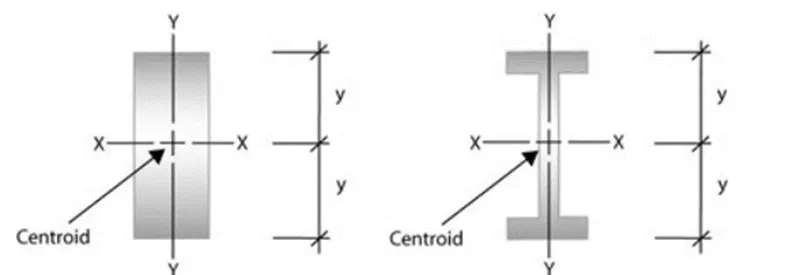
Area Moment of Inertia:
The area moment of inertia of a beam cross section area measures the beam ability to resist bending. The larger the moment of inertia less will be the bend.
σ =M* Y/I
Where,
M is the bending Moment
Y is the distance between extreme point and neutral fiber
I is the Moment of inertia
Thus the Equation is simplified as
σ = M/S
Neutral Axis:
It is the direct measure of strength in the beam, larger the section modulus greater the load bearing capacity and higher the resistance to bending.
When beam is subjected to pure bending the top most fibers of the beam are subjected to maximum compression, while the bottom most fiber of the beams are subjected to maximum tension.
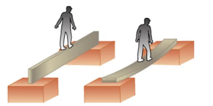
This picture contains the following scene, Diagram of a beam on its narrow edge supported at both ends. A man is walking on a straight beam. Diagram of a beam resting on its flat side supported at both ends. A man is walking on the straight beam and its bending in the middle.
Calculation:
Case 1: Before Optimization
The hood which was already created is imported and the section inertia analysis is done.
We have to make sure that the curve obtained is a single/closed curve.
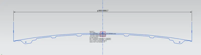
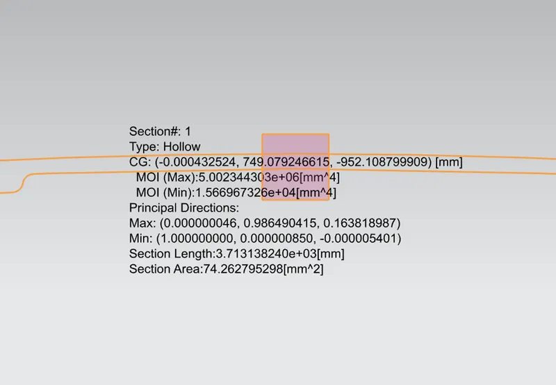
I (Max) = 5.002344303e+06[mm^4]
I (Min) = 1.566967326e+04[mm^4]
As per the section modulus equation,
S=I/Y
Soln.
I = 15669.67326 mm^4
Y = Total distance / 2
Total distance = 888.7 mm
Y= 888.7/2 = 444.35 mm
S = 15669.67326/ 444.35
S = 35.2642585 mm^3
Case 2: After Optimization
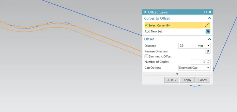
The hood inner panel’s curve is offset by 0.5mm outwards and section inertia analysis is done the
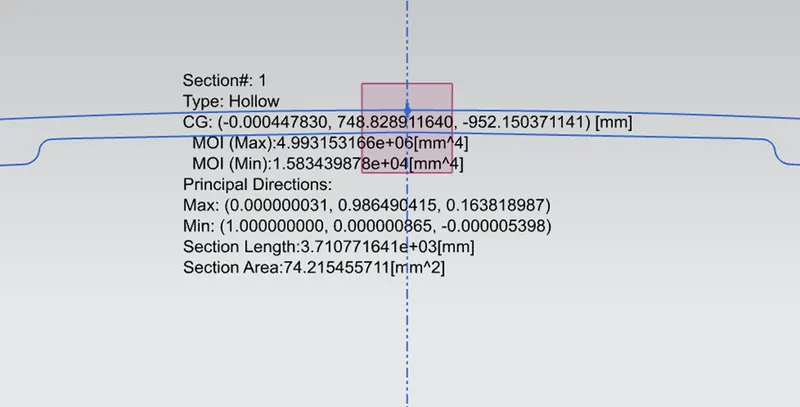
I (Max) = 4.993153166e+06[mm^4]
I (Min) = 1.583439878e+04[mm^4]
As per the section modulus equation,
S=I/Y
Soln.
I = 15834.39878 mm^4
Y = Total distance / 2
Total distance = 888.7 mm
Y= 888.7/2 = 444.35 mm
S = 15834.39878 / 444.35
S = 35.634969686 mm^3
Conclusion:
Thus Section Modulus carried out on BIW Structures provide better understanding of the Load bearing capacity, bending resistance and forces and stress exerted in the beam and has wider significance of reducing the weight and cost for Automotive OEM's.