Section Modulus calculation and optimization
SECTION MODULUS (Z)
It is a way of quantifying a cross-section of a given geometry. It is directly proportional to the area moment of inertia of the cross-section. Higher the section modulus, the more the moment of inertia, more stiffness and thus more resistance to deformation and bending. Section modulus can also be improved by varying the geometry of the cross-section. In other words, stiffness can be improved by just improving the geometry without the need for adding extra material.
MOMENT OF INERTIA(I)
The moment of inertia of an object is a determined measurement for a rigid body rotating around a fixed axis. The axis might be internal or external, and it can be fixed or not. However, the moment of inertia (I) is always described in relation to that axis.
The moment of Inertia depends on the distribution of the mass around its axis of rotation. MOI varies depending upon the position of the axis that is chosen. That is, depending on the location and direction of the axis of rotation, the same item might have various moment of inertia values.
Angular mass or rotational inertia are other names for the moment of inertia.
The SI unit of moment of inertia is kg mm2.
SECTION MODULUS (Z): I/Y(MIN)
M/I = σ/Y
M = σ*Z
MATERIAL DATA
Stainless steel AISI 302 – cold-rolled
YIELD STRENGTH = 520 MPa
The following are few iterations performed over the ENGINE HOOD cross-section.
1. Inner and Outer panel with 0mm offset as per the actual master section.
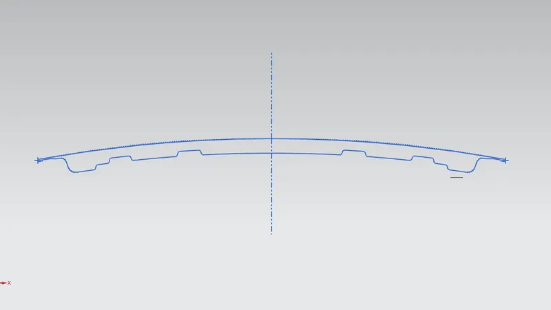
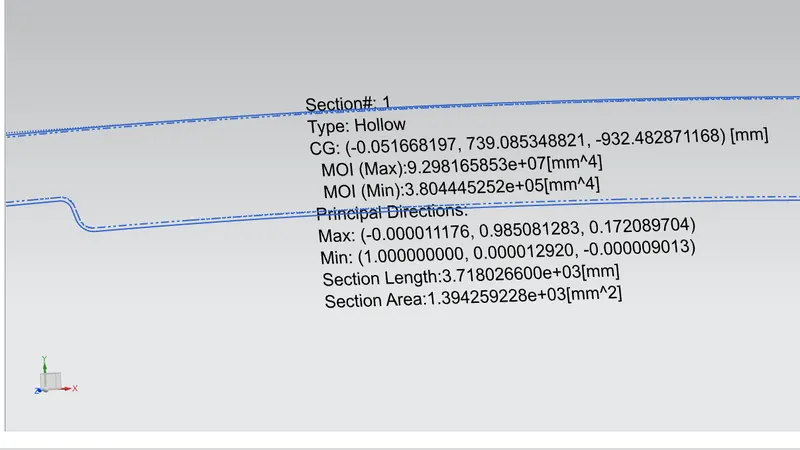
I(MIN)= 3.804445252 X 10^5 mm^4; Y=440.6 mm
Z=I/Y=864.646648182
Bending moment (M)=Z*σ(yield)=449616.257055N-mm^2
2. Inner and Outer panel with 1mm offset. No geometry changes.
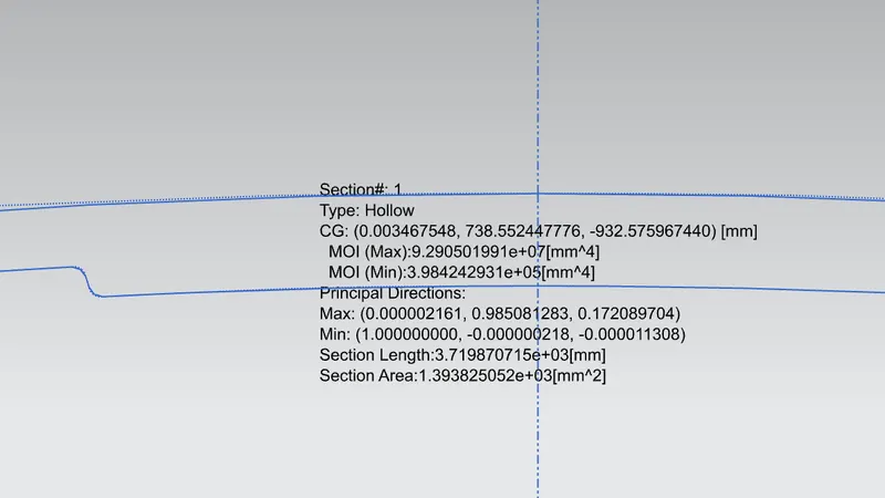
I(MIN)= 3.9842422931 X 10^5 mm^4; Y=440.6 mm
Z=I/Y=864.646648182
Bending moment (M)=Z*σ(yield)=470864.998275N-mm^2
2. Inner and Outer panel with 2mm offset. No geometry changes.
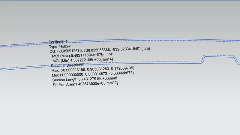
I(MIN)= 4.58720 X 10^5 mm^4; Y=440.6 mm
Z=I/Y=1042.5454
Bending moment (M)=Z*σ(yield)=542123.63N-mm^2
2. Inner and Outer panel with 3mm offset. No geometry changes.
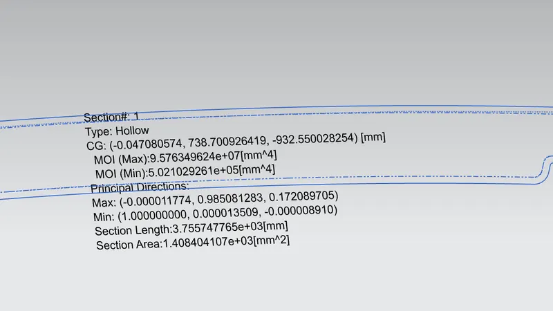
I(MIN)= 5.0210X 10^5 mm^4; Y=440.6 mm
Z=I/Y=1141.136
Bending moment (M)=Z*σ(yield)=593390.90N-mm^2
CONCLUSION
Different sections, as shown above, were tried in order to achieve a higher moment of inertia. It is observed that increasing the gap between the inner and outer panels has resulted in decreasing bending moments. No significant change in section modulus is observed just by increasing the gap between the panels. On the contrary, if we tend to add more geometric features to the master section resulted in a drastic increase in section modulus. Hence it is best to add more geometric features to the master section to improve the stiffness of a section. However, this could result in an increase in manufacturing cost.