Section Modulus calculation and optimization
CALCULATING AND OPTIMIZING THE SECTION MODULUS OF DESIGNED CAR HOOD USING NX-CAD SOFTWARE
Objective:
To calculate the section modulus using the hood cross section and to come up with new section of optimized section modulus as compare to the previous section in order to increase the stregth and stiffness of the hood.
Introduction:
Section modulus is the geometric property of any component or shaft or beam structural cross-sections.It determines a object's strength and ability to resist external forces which flex the object.The moment carrying capacity of an any object is directly dependent on geometrical property and material property.Geometry of an object plays an important role in load carrying capacity of an object.A component having larger section modulus will be stronger, stiffness and capable of supporting greater loads.Therefore section modulus is the predominant factor which evidences the strength of an object.
There are two types of section moduli, the elastic section modulus (s) and plastic section modulus (z).The plastic section modulus is used for materials where (irreversible) plastic behavior is dominant.The majority of designs do not intentionally encounter this behavior.
But for general designs, the elastic section modulus is used, applying up to the yield point for most metals and other common materials.The definition of section modulus according to mechanics is as follows-the ratio of the momemt of inertia of area and the distance from the neutral axis to any given (or extreme) fiber.
Therefore section modulus, S=I/y(unit is mm³)
where,
- I-Area moment of inertia(mm⁴)
- y-Distance between neutral axis and extreme end of fiber(mm).
Procedure for calculating section modulus:
In this project, section modulus can be calculated on the two cases.
Case 1-Without changing the cross section of hood
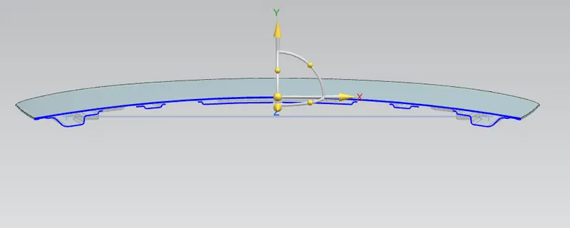
- For calculating the section modulus, a cross section of hood is required.For that, Mirror plane (datum plane )at centre of hood as shown.
- Using the intersection curve feature, generate the section curves of hood outer and inner panel using created datum plane as common plane intersection.
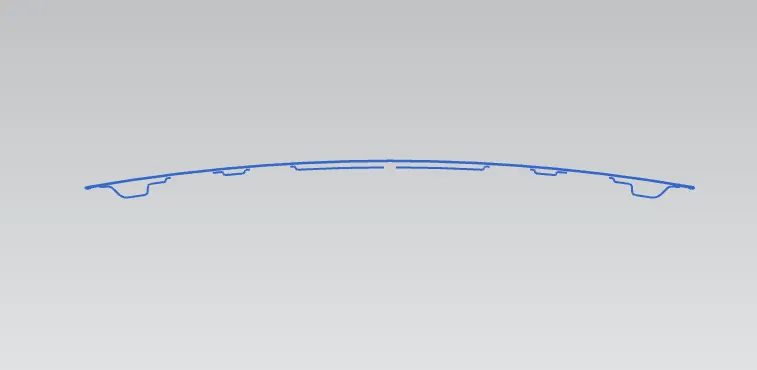
- Then after using quick trim, trim unnecessary curves.
- Using make corner feature, join the extreme ends of hood outer and inner panel curves.
- Join all the discontinuity curves using the through splines feature.
- Join all curves with 2d studio spline in tool bar.
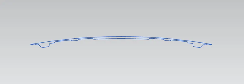
- Once the closed profile is created, go with the section inertia analysis and select the existing intersection curve.
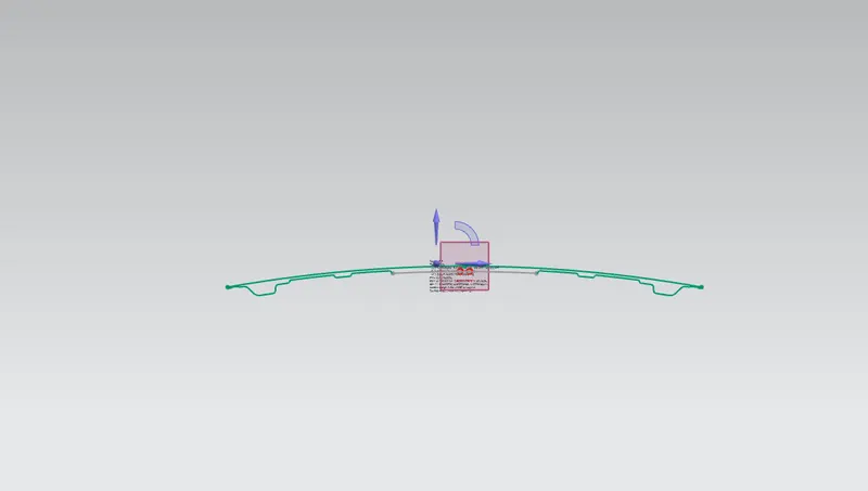
- Then all the sectional parameters will be obtained as shown below.
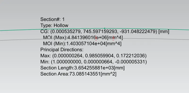
- From the above figure, we can found out-
Required area moment of inertia,MOI(min):1.403057104e+04[mm⁴]
- Then after create the construction lines at center, end and measure the distance between them.
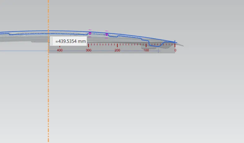
- From the above figure, we can found out-
-
Distance between neutral axis and extreme end of the fibre, y=439.5354 mm
Calculation for case1-
Moment of inertia of area(I)= 1.403057104 X 10⁴mm⁴
Distance, y= 439.5354 mm
Therefore,
Section modulus, S=Moment of inertia of area(I)/Distance between neutral axis and extreme end of fiber
S= 1.403057104X 10⁴mm⁴/439.5354mm
= 14030.57104 mm⁴/439.5354mm
S= 31.92136 mm³
Case 2-(Optimization-Changing section of hood by increase the distance between outer and inner panel)
According to the definition of section modulus, if the area of cross section of object changes,the area moment of inertia will also changes and result in changing the section modulus because of direct proportionality.So here, I can changing area of cross section of hood for better section modulus.As in the designing of hood, the clearance between outer and inner panel is given as 0.2mm.But for better section modulus,I have increasing additional distance of 0.5mm between the hood outer and inner panel.
So for calculating the section modulus-
- First increase the additional distance of 0.5mm between outer and inner panel and after that similarly as case1, trim the unnecessary curves and join the discontinuity curves.So that closed scetion curve will be obtained.
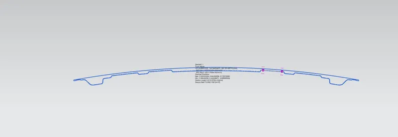
- Then all the new sectional parameters will be obtained as shown below.
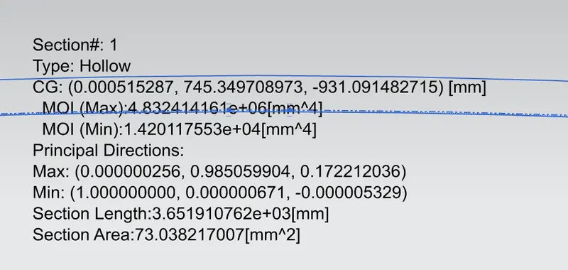
- From the above figure, we can found out-
Required area moment of inertia,MOI(min):1.420117553e+04[mm⁴]
- The distance(y) between neutral axis and extreme end of the hood is same as case1, because here only change the clearance between outer and inner distance but not change in length of hood.
so distance between neutral axis and extreme end of the fibre, y=439.5354 mm
Calculation for case2-
Moment of inertia of area(I)= 1.420117553X 10⁴mm⁴
Distance, y= 439.5354mm
Therefore,
Section modulus, S=Moment of inertia of area(I)/Distance between neutral axis and extreme end of fiber
S= 1.420117553 X 10⁴mm⁴/439.5354mm
= 14201.17553 mm⁴/439.5354mm
S= 32.3095mm³
Comparison of both cases for better section modulus-
| CASE 1 | CASE 2 | |
| MOI | 1.403057104X 10⁴mm⁴ | 1.420117553 X 10⁴mm⁴ |
| DISTANCE (Y) | 439.5354 | 439.5354 |
| SECTION MODULUS | 31.92136 | 32.3095 |
| STRENGTH | LESS | MORE |
As already known, higher in the section modulus of structure, the more the strength and resistive against bending.so as in the comparison of above cases, case-2 having more section modulus than case-1 because of increasing clearance distance of 0.5mm between hood outer and inner panel.So the hood with case-2 can withstand and capable of supporting greater loads.
Conclusion:
Section modulus of the designed hood can be calculated effectively and also gave the optimized section modulus with new section for to increase the strength of the hood.