Section Modulus calculation and optimization
Section Modulus calculation and optimization
Objective: To find the section modulus of the hood and optimisation to improve the overall section modulus.
Introduction
The moment of inertia of an object is a calculated measure for a rigid body that is undergoing rotational motion around a fixed axis: that is to say, it measures how difficult it would be to change an object's current rotational speed. That measurement is calculated based upon the distribution of mass within the object and the position of the axis, meaning that the same object can have very different moment of inertia values depending upon the location and orientation of the axis of rotation.
Section Modulus: The section modulus (S) is geometric property of the cross section used for designing beams and flexural members. It does not represent anything physically.
Formula of Section Modulus: It may be defined as the ratio of total moment resisted by the section to the stress in the extreme fibre which is equal to yield stress.
S = I/Y, Where
S = Section modulus (mm^3)
I = Moment of Inertia of the section about the bending axis. (mm^4)
Y = Distance between the neutral axis and extreme end of the object (mm)
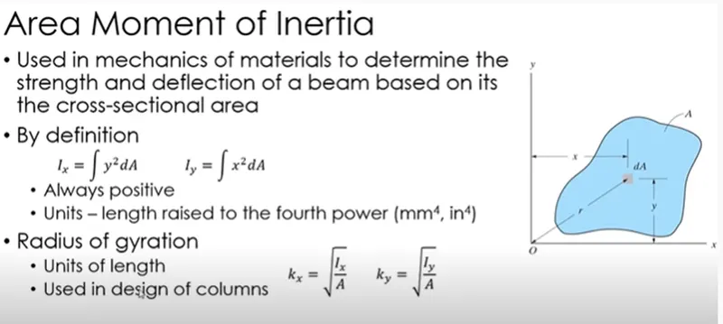
Area moment of Inertia:
The area moment of inertia is a property of a two-dimensional plane shape which characterizes its deflection under loading. It is also known as the second moment of area or second moment of inertia. The area moment of inertia has dimensions of length to the fourth power.
The first moment of area is the distribution of the area of a shape around a rotational axis. It is used to find the centroid of an area. The unit is in a cubic meter.
The second moment of area or second area moment is the dispersion of points of a shape in an arbitrary axis.
Bending Movement Equation
Bending theory is also known as flexure theory is defined as the axial deformation of the beam due to external load that is applied perpendicularly to a longitudinal axis which finds application in applied mechanics.
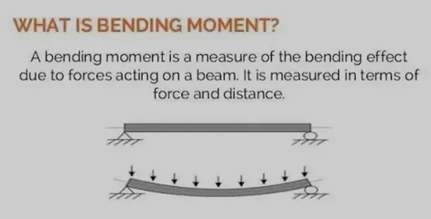
For a material, flexural strength is defined as the stress that is obtained from the yield just before the flexure test. It represents the highest stress that is experienced within the material at the moment of its yield. 𝜎 is used as the symbolic representation of flexural strength
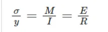
σ =yield strength
Y = Distance between the neutral axis and extreme end of the object (mm)
M = Bending moment
I = Area moment of Inertia
E = Young’s modulus
R = Radius of gyration
In solid mechanics, a bending moment is the reaction induced in a structural element when an external force or moment is applied to the element, causing the element to bend. The most common or simplest structural element subjected to bending moments is the beam
Material Data:
Stainless steel AISI 302 – cold rolled
Where yield strength of stainless steel is 520MPa = 520 N/mm^2
Neutral axis: When beam is subjected to pure bending the top most fibres of the beam are subjected to maximum compression, while the bottom most fibres of the beams are subjected to maximum tension.
Here
Neutral axis is Y= 480.7492 mm
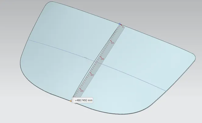
We need to take the lowest value of MOI.The lowest value of MOI determines the starting point of breakage. Here MOI (max)>MOI(min), so MOI(min) is to be taken for calculation.
Calculation:
CASE 1: Before Optimization
The Hood which was already created in hood design is imported and the section inertia analysis is done.
We have to make sure that the curve obtained is a closed curve. To find MOI
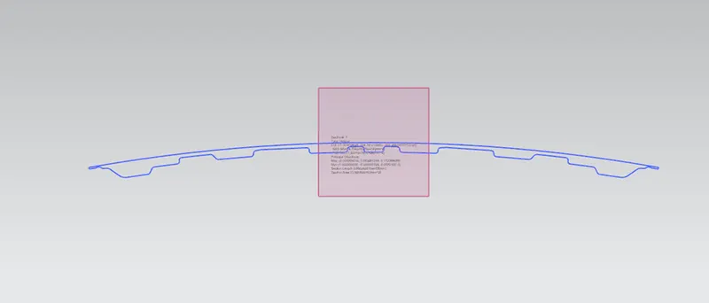
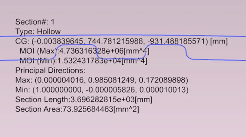
MOI (max) = 4.736316328e+06 (mm^4)
MOI (min) = 1.532431783e+04(mm^4)
As per the section modulus equation,
S = I/Y
I = MOI (min) value is considered
Y = Total distance /2,
Total distance =480.7492 mm
Y = 480.7492 / 2
= 240.3746 mm
Therefore,
S=63.7518 mm^3
M/I = σ/Y
M = σ*S
M=240.3746*520 (N/mm^2*mm^3)
M=33150.94N-mm
M=33.150 N-M
CASE 2: After optimization
The hood inner panel’s curve is offset by 5 mm outwards and section inertia analysis is done same as case 1 for a closed curve.
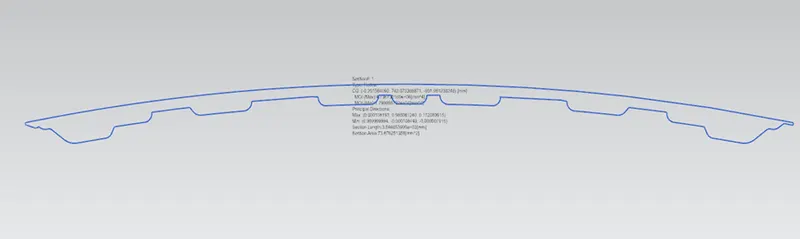
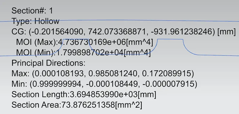
MOI (max) = 4.736730169e^06 mm^4
MOI (min) = 1.799898702e^04 mm^4
As per section modulus equation,
S = I / Y
I = MOI (min) value is considered
Y = Total distance /2,
Total distance =480.7492mm
Y = 480.7492 / 2
= 240.3746mm
Therefore,
S=74.8789mm^3
M/I = σ/Y
M = σ*S
M=74.8789*520 (N/mm^2*mm^3)
M=38937.03N-mm
M=38.93N-M
Result:
Hence when comparing case 1 & case 2,
- Case1
S=63.7518 mm^3
M=33.150 N-M
- Case 2
S=74.8789mm^3
M=38.93N-M
- The section modulus value of case 2 is higher than the case 1
- As we increase the section area, the moment of inertia & section modulus increases which means strength and load material also increase
Conclusion:
Different sections, as shown above, were tried in order to achieve a higher moment of inertia. It is observed that increasing the gap between the inner and outer panels has resulted increasing bending moments. No significant change in section modulus is observed just by increasing the gap between the panels. On the contrary, if we tend to add more geometric features to the master section resulted in a drastic increase in section modulus. Hence it is best to add more geometric features to the master section to improve the stiffness of a section. However, this could result in an increase in manufacturing cost.