Section Modulus Calculation and Optimization of Hood Design
SECTION MODULUS CALCULATION AND OPTIMIZATION OF HOOD DESIGN
Objective:
The main objective of this report is to explain the details about section modulus, how this section modulus value is calculated for the hood design and then how the design is optimized to improve its section modulus.
Description:
Section modulus:
Section modulus is a geometric property for a given cross-section used in the design of beams or flexural members. Other geometric properties used in design include area for tension and shear, radius of gyration for compression, and moment of inertia and polar moment of inertia for stiffness.
The section modulus of the cross-sectional shape is of significant importance in designing beams. It is a direct measure of the strength of the beam. A beam that has a larger section modulus than another will be stronger and capable of supporting greater loads.
It includes the idea that most of the work in bending is being done by the extreme fibres of the beam, i.e., the top and bottom fibres of the section. The distance of the fibres from top to bottom is therefore built into the calculation. There are two types of section moduli,
- Elastic section modulus and
- Plastic section modulus.
Elastic section modulus:
For general design, the elastic section modulus is used, applying up to the yield point for most metals and other common materials.
The elastic section modulus is defined as,
S = I/Y
Were,
S = section modulus
I = moment of inertia
Y = is the distance from the neutral axis to the most extreme fibre.
Plastic section modulus:
The plastic section modulus is used for materials where elastic yielding is acceptable and plastic behaviour is assumed to be an acceptable limit. Designs generally strive to ultimately remain below the plastic limit to avoid permanent deformations, often comparing the plastic capacity against amplified forces to stresses.
The plastic section modulus depends on the location of the plastic neutral axis (PNA). The PNA is defined as the axis that splits the cross section such that the compression force from the area in compression equals the tension force from the area in tension. So, for sections with constant yielding stress, the area above and below the PNA will be equal, but for composite sections, this is not necessarily the case.
The plastic section modulus is the sum of the areas of the cross section on each side of the PNA (which may or may not be equal) multiplied by the distance from the local centroids of the two areas to the PNA.
The plastic section modulus is used to calculate the plastic moment, Mp, or full capacity of a cross-section. The two terms are related by the yield strength of the material in question, Fy,
MP = FY . Z
Plastic section modulus and elastic section modulus are related by a shape factor which can be denoted by K, used for an indication of capacity beyond elastic limit of material. This could be shown mathematically with the formula,
K = Z/S.
Section modulus calculation:
For this project, previously designed hood assembly is taken for the section modulus calculation. The steps involved in this calculation are,
- The previously designed hood assembly is taken, then a new datum plane is created parallel to the xy plane at the centre curve of the hood outer panel.
- With respect to this datum plane, an intersection of the hood assembly is taken, then the top curve of outer panel and bottom curve of inner panel of this 3D curve is converted to 2D sketch with the help of project curve.
- After projecting the curve, lines and studio splines are used to fill the gaps in curve to make its as a closed profile. Then section inertia analysis command is applied to the sketch to get the centre of gravity, moment of inertia, length and area of the hood assembly at the section.
- Likewise, the centre of gravity, moment of inertia, length and area of the hood assembly at section along the yz plane is derived.
- The distance from the neutral axis to the extreme fibre is measured along both the cross-sections.
- These values are substituted in the elastic section modulus formula to obtain the section modulus value.
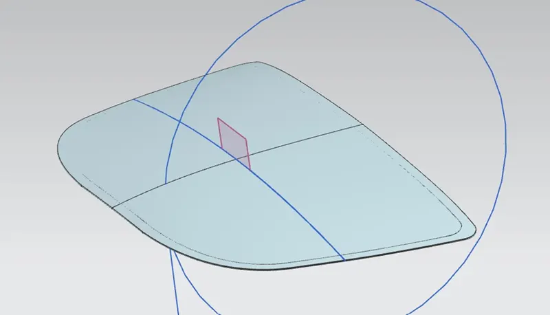
Intersection along the datum plane which is created parallel to xy plane is shown.
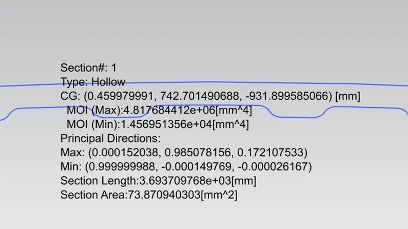
Section inertia analysis result is shown.
According to the analysis,
Maximum moment of inertia (Imax) = 4.817684412*106 mm4 and
Minimum moment of inertia (Imin) = 1.456951356*104 mm4
For resistance towards bending of a section, we have to consider the minimum moment of inertia value for section modulus calculation.

Distance between the extreme fibre is shown.
We need only the distance from the neutral axis. So,
= 878.6108/2
The total distance between the neutral axis and the extreme fibre is,
Y = 439.3054 mm.
According to the elastic section modulus formula,
S = I/Y
Smin = Imin/Y => (1.456951356*104) / 439.3054
Smin = 33.1648 mm3.
Optimization:
After calculating the section modulus, some optimization is done to the design to increase its cross-section area. If the cross-section increases the section modulus will also increase to provide more strength. To achieve this the bottom curve in sketch is offset to 0.9mm below. It represents the area between the top curve of outer panel and bottom curve of inner panel of the hood.
Then section inertia analysis command is applied to derive the necessary values like before,
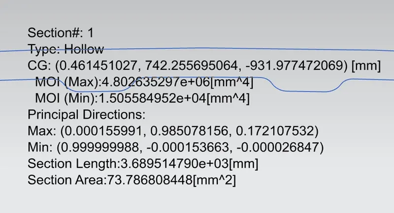
Optimized section inertia analysis result is shown.
According to the analysis,
Maximum moment of inertia (Imax) = 4.802635297*106 mm4 and
Minimum moment of inertia (Imin) = 1.505584952*104 mm4
Y value remains the same, Y = 439.3054 mm.
As we seen early, minimum moment of inertia is considered,
Smin = Imin/Y => (1.505584952*104) / 439.3054
Smin = 34.2719 mm3.
The optimized design shows the 3.5% improvement in its section modulus value which is further improved by increasing the cross-section between hood inner and outer panel if needed. But for now, this improvement is enough when compared to the initial design. And my hood design can with stand the required resistance to bending.
Conclusion:
The details about the section modulus and the steps involved in calculating the section modulus and optimization of the hood design is explained with reference images for clear understanding. And I also conclude that, my hood design is improved than before.