Section Modulus calculation and optimization
SECTION MODULUS USING THE FORMULA
OBJECTIVE: To increase the Section Modulus of the hood by necessary changes using NX cad.
It is termed as the ratio of the second moment of area and distance from N.A (Neutral axis) to the extreme fiber. Also, it is the measure of the strength of the given member. The stress in the outermost section of the beam is computed with the help of section modulus. It is indicated by S.
Section modulus is indicated as follows:
S=I/Y
Here, I is “moment of inertia”
y is the distance from the “ neutral axis ” to the top or bottom of fiber.
The Unit of a “section modulus” is in.3 (mm3)
Section modulus depends only on the cross-section shape of the structure. For symmetric sections, the value of “section modulus” is for both above and below of centroid of the fiber. An asymmetric section has two values for top and bottom of the fiber due to different distance from the centroid to the top and bottom of the material, the maximum “section modulus” is S max and the minimum section modulus is S min.
Importance:
- It is significant for beam and flexural member design.
- More the section modulus, the more the member is resistant to the bending of the beam.
- It is easier to calculate stresses in the beam and an exact measure of the strength of steel.
- If two beams are made of the same material and comparing the “section modulus” of two beams, the beam with bigger section modulus will be tougher and more capable to withstand larger loads.
Section Modulus calculation of the Hood Design:
CASE 1: Initial Hood Design.
Area Moment of Inertia: I(min)
SECTION MODULUS (S): I/Y(MAX)
I= AREA MOMENT OF INERTIA OR SECOND ORDER MOMENT OF INERTIA.
Y(MAX)= DISTANCE OF EXTREME LAYER FROM NEUTRAL AXIS.
Alternatively, it can also be defined by the below formula
M/I = σ/Y
M = σ*S
σ= YIELD STRENGTH
S= SECTION MODULUS
MATERIAL DATA
STAINLESS STEEL :AISI 302 – cold-rolled
YIELD STRENGTH = 520 MPa
The following are few iterations performed over the ENGINE HOOD cross-section.
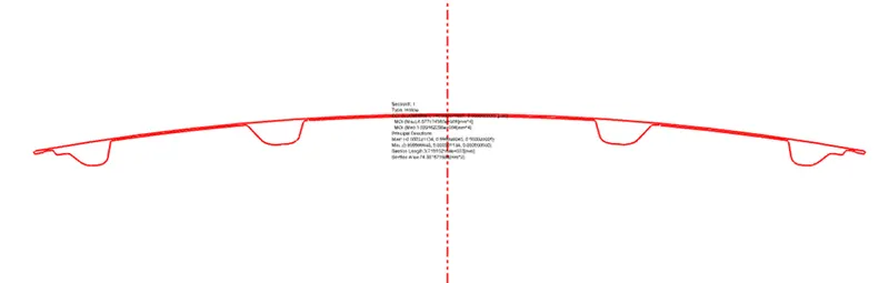
- Inner and Outer panel with 2mm offset as per the actual master section.
I(MAX): 4.877 X 10^6 mm^4; Y:440.6 mm
S=I/Y= 11069 mm^3
Bending moment (M)=S*σ(yield)=5755880 N-mm
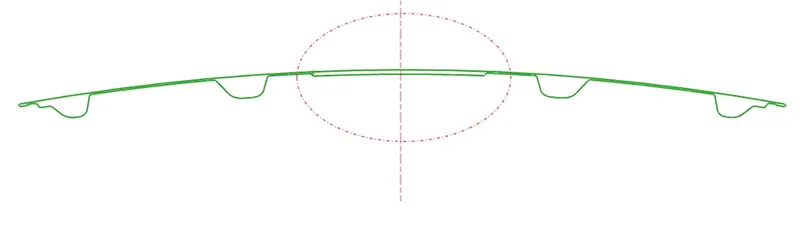
- Inner and Outer panel with 2mm offset with geometry changes to the inner panel as shown below.
I(MAX): 5.2893 X 10^6 mm^4; Y:440.6 mm
S=I/Y= 12005 mm^3
Bending moment (M)=S*σ(yield)=6242600 N-mm
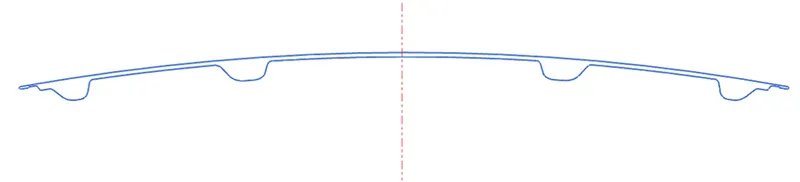
- Inner and Outer panel with 5mm offset. No geometry changes.
I(MAX): 4.839 X 10^6 mm^4; Y:440.6 mm
S=I/Y= 10983 mm^3
Bending moment (M)=S*σ(yield)=5711160 N-mm
- Inner and Outer panel with 4mm offset. No geometry changes.
I(MAX): 4.862 X 10^6 mm^4; Y:440.6 mm
S=I/Y= 11035 mm^3
Bending moment (M)=S*σ(yield)=5738200 N-mm

Increased MOI:
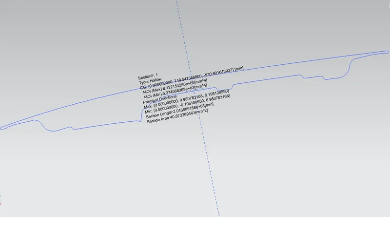
Final result: Thus the stiffness of the car hood has been increased by increasing its area moment of inertia.
Conclusion:
Section modulus is directly dependent on the area moment of inertia and the distance from the neutral axis. Hence, to improve the geometry of the carry more bending load, the section modulus can be improved by increasing the area MOI of a given section.
We can increase the section modulus just increasing the gap between the outer & inner panel.