Section Modulus calculation and optimization
CALCULATING THE SECTION MODULUS OF THE HOOD OF A CAR AND OPTIMIZING IT FOR BETTER RESULTS
OBJECTIVE
The objective of the project is to find the section modulus of the designed front hood and optimizing it to get an improved section modulus compared to the previous section.
INTRODUCTION
Section modulus is a geometric property for a given cross-section used in the design of beams or flexural members. Other geometric properties used in design include area for tension and shear, radius of gyration for compression, and moment of inertia and polar moment of inertia for stiffness. Any relationship between these properties is highly dependent on the shape. There are two types of section moduli, the elastic section modulus and the plastic section modulus.
The elastic section modulus is defined as,
S = I / y
Where,
- S is the Section Modulus
- I is the second moment of area (or area moment of inertia, not to be confused with moment of inertia)
- y is the distance from the neutral axis to any given fibre. It is often reported using y = c, where c is the distance from the neutral axis to the most extreme fibre.
It is also often used to determine the yield moment (My) such that,
My = S × σy
Where, σy is the yield strength of the material.
The neutral axis is an axis in the cross section of a beam (a member resisting bending) or shaft along which there are no longitudinal stresses or strains. If the section is symmetric, isotropic and is not curved before a bend occurs, then the neutral axis is at the geometric centroid. All fibers on one side of the neutral axis are in a state of tension, while those on the opposite side are in compression.
SECTION MODULUS CALCULATION
For finding the better results I have analysed two sections and considered it as case 1 and case 2 and again the two sections were optimized and analysed and then compared to get better results.
STEPS
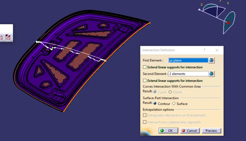
Take intersection of the part with yz plane.
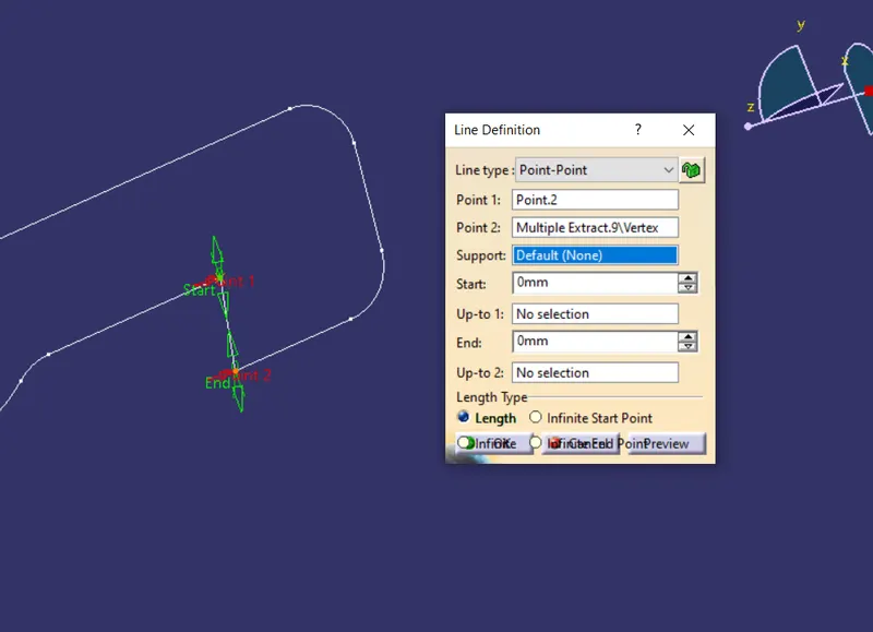
create point on the line
and split the line and join it with line at both side.
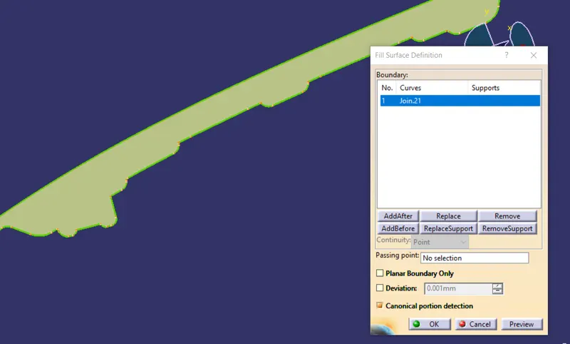
join the intersecting lines and fill it.
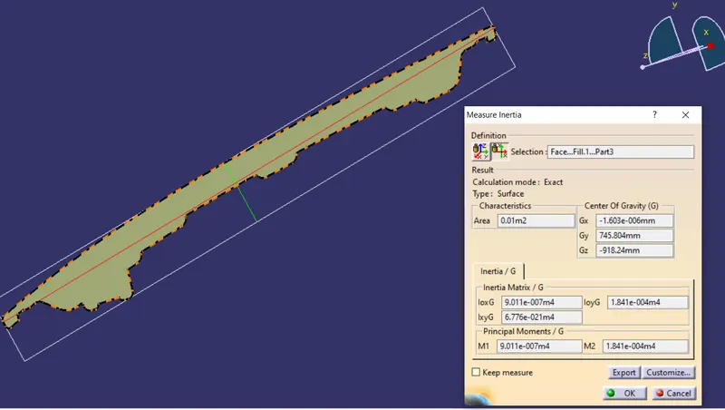
use measure inertia tool
------------------------------------------------------------------------------------------------------------------------------------------------------------------------------------------------------------------------
Product : Face...Fill.1...Part3
Date : Sunday, 25 July 2021 20:14:03
Author : Aejaz
------------------------------------------------------------------------------------------------------------------------------------------------------------------------------------------------------------------------
Component | Sub-Component | Area[m2] | Gx[mm] | Gy[mm] | Gz[mm] | M1[m4] | M2[m4] | IoxG[m4] | IoyG[m4] | IxyG[m4] |
------------------------------------------------------------------------------------------------------------------------------------------------------------------------------------------------------------------------
Face...Fill.1...Part3 | | 0.010 | -1.60289e-006 | 745.804 | -918.240 | 9.01142e-007 | 0.000184064 | 9.011e-007 | 1.841e-004 | 2.365e-018 |
------------------------------------------------------------------------------------------------------------------------------------------------------------------------------------------------------------------------
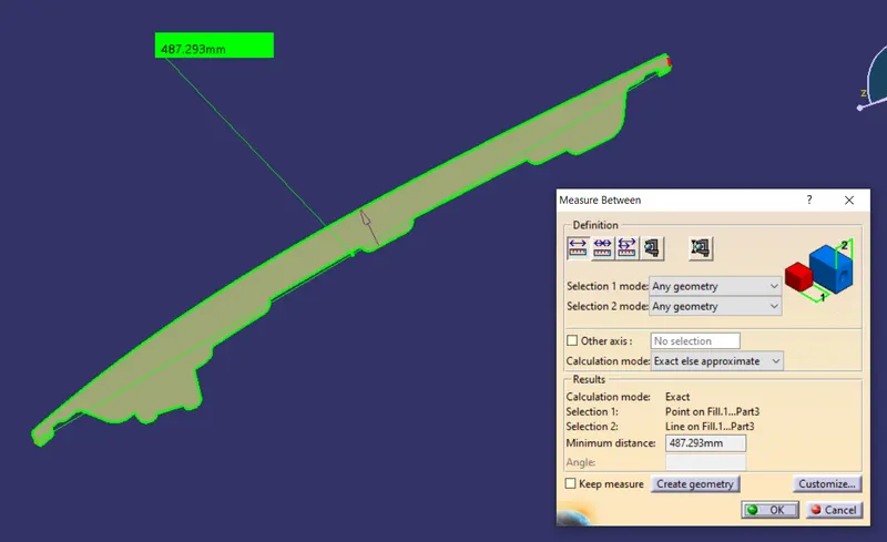
measuring total distance and we have to take half distance from neutral axis
CALCULATION
we got total 487.293mm length
we need to take 487.293/2=243.646
Y=243.646mm
I=9.011*10^7m^4
calculating section modulus for first section
S = I/y
S = 9.011*10^7/243.646
S = 39.414*10^6mm^4
calculation for next part,
take parallel curve for the down intersection of 0.5mm
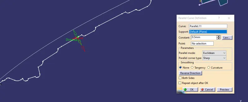
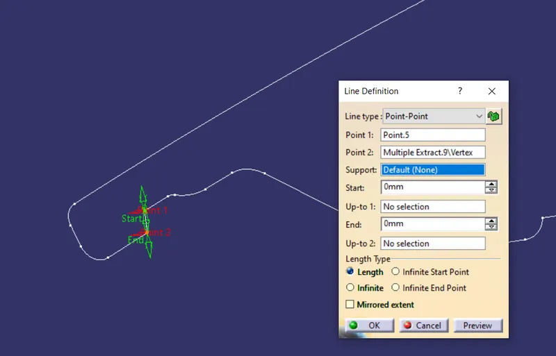
now split the curve with the point and join the two curve with line at both end,
and fill it
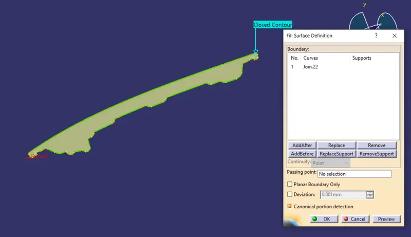
go for measure inertia and measure part
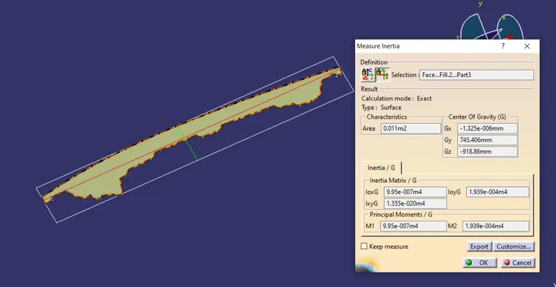
------------------------------------------------------------------------------------------------------------------------------------------------------------------------------------------------------------------------
Product : Face...Fill.2...Part3
Date : Sunday, 25 July 2021 20:42:36
Author : Aejaz
------------------------------------------------------------------------------------------------------------------------------------------------------------------------------------------------------------------------
Component | Sub-Component | Area[m2] | Gx[mm] | Gy[mm] | Gz[mm] | M1[m4] | M2[m4] | IoxG[m4] | IoyG[m4] | IxyG[m4] |
------------------------------------------------------------------------------------------------------------------------------------------------------------------------------------------------------------------------
Face...Fill.2...Part3 | | 0.011 | -1.32491e-006 | 745.406 | -918.860 | 9.94957e-007 | 0.000193944 | 9.95e-007 | 1.939e-004 | 4.337e-019 |
------------------------------------------------------------------------------------------------------------------------------------------------------------------------------------------------------------------------
CALCULATION FOR SECOND SECTION,
S = I/y
here, I= 9.95*10^7m^4
Y=243.646mm
S = 9.95*10^7/243.646
S = 41.269*10^6mm^4
conclusion
So decreasing the distance between two panels leads to increase in section modulus, so resistance to bending also increases, and strength of hood also increases.