Section Modulus calculation and optimization
Objective: The objective of this project is to find the section modulus of the designed front hood and optimizing it to get an improved section modulus compared to the previous section.
Introduction
Moment of Inertia
When a body is free to rotate around an axis, torque must be applied to change its angular momentum. The amount of torque needed to cause any given angular acceleration (the rate of change in angular velocity) is proportional to the moment of inertia of the body.Moment of inertia may be expressed in units of kilogram metre squared (kg·m2) in SI units.
Mathemetically,
I= m x r^2
Where, m= Sum of the product of the mass
r= Distance from the axis of the rotation
Section Modulus:
Section modulus is a geometric property for a given cross-section used in the design of beams or flexural members. Other geometric properties used in design include area for tension and shear, radius of gyration for compression, and moment of inertia and polar moment of inertia for stiffness. Any relationship between these properties is highly dependent on the shape in question. Equations for the section moduli of common shapes are given below. There are two types of section moduli, the elastic section modulus and the plastic section modulus.
Mathemetically,
S=I/Y
Where, I= Moment of inertia
Y= Distance from the neutral axis to the outer fibre
Procedure:
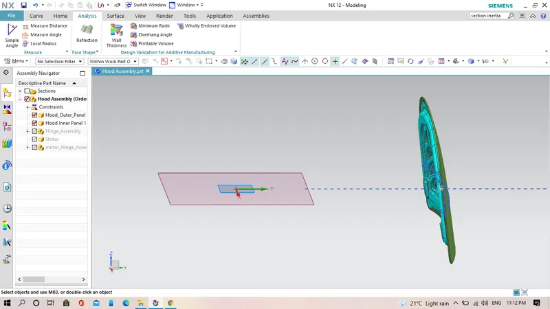
1. Obtain the cross-section of the hood panel both inner & outer panel.
First create a datum plane in the middle of the hood and using the option intersection curve, we get the cross-section of the hood panel.
2. To perform the 'Section inertia analysis' we need to have a closed surface. So, we enter the sketcher work bench ans opt only the required curves (outer curve/fibre of inner hood panel and outer hood panel) and gaps are covered using 'Studio spline' option. Finally, trim out the extra portion and we have a closed fibre (Cross-section).
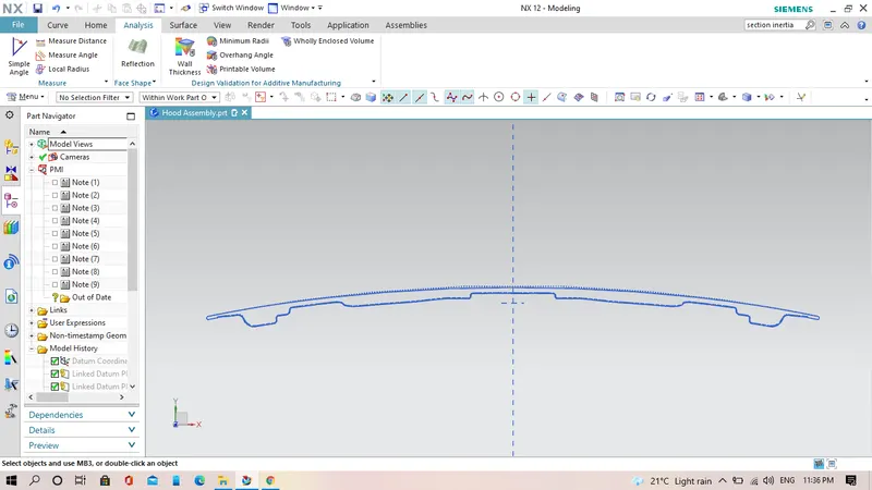
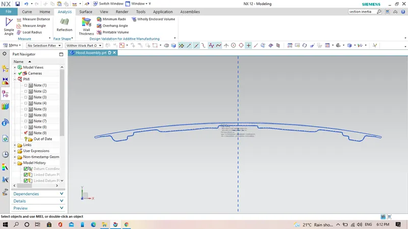
3. Exit the sketch work bench, and opt 'Section inertia modulus' now select the sketch and press ok.
I got following details of the cross-section as shown in the image.
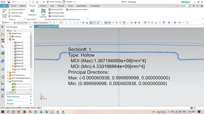
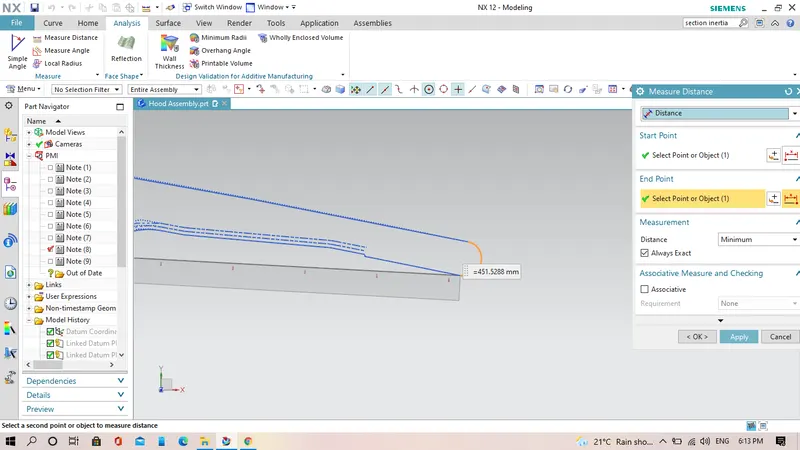
Measure the distance from the neutral axis to the outer fibre.
We consider the MOI(Min) to understand what is the
MOI (Max)=1.367194889 x 10^8 mm^4
MOI (Min)=4.33019898 x 10^5 mm^4
Distance from center of the hood to the end of the hood=451.5288 mm
We will consider approximate value, Y=452 mm
Section modulus (s)= Moment of inertia (MOI)/Distance (Y)
S=I/Y
For maximum moment of inertia
S=1.367194889 x 10^8/452
=30.2467453539 x 10^4 mm^3
For minimum moment of inertia
S=4.33019898 x 10^5/452
=0.9580086238938 x 10^3 mm^3
4. Now we need to make some changes in hood design for better section modulus results, w.k.t to have a better section modulus we need to have a good M.O.I(min) for which the cross-section of the panel should be increased. So, i have offset the outer fibre of the inner hood panel in outward direction to 0.5 mm distance. Finally, perform the section inertis modulus analysis and following data as shown in figure and received.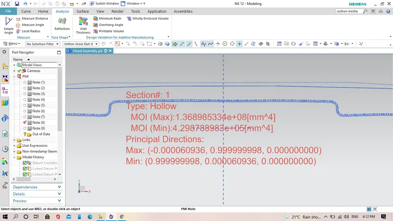
For which i got following result.
MOI (Max)=1.368985334 x 10^8 mm^4
MOI (Min)=4.298788983 x 10^5 mm^4
Distance from cemter of the hood to the end of the hood=451.5288 mm
We will consider approximate value, Y=452 mm
Section modulus (s)= Moment of inertia (MOI)/Distance (Y)
S=I/Y
For maximum moment of inertia
S=1.368985334 x 10^8 /452
=30.28728615044 x 10^4 mm^3
For minimum moment of inertia
S=4.298788983 x 10^5 /452
=0.6264853561082 x 10^3 mm^3
Conclusion:
For this experiment we can conclude that by increasing the distance between the top and lower face of the hood we get increased value of section modulus.