Section Modulus calculation and optimization
Section Modulus
Aim - Use the Section from your Hood design and calculate the section modulus using the formula S = I/y.
Section modulus is a geometric property for a given cross-section used in the design of beams or flexural members. It is the direct measure of the strength of the component. Higher the section modulus of a structure, the more the resistive it becomes to bending.
Section Modulus is the ratio of moment of Second moment of area (Moment of Inertia) and distance from the neutral axis from the outermost fibre. The stress in the outermost section of the beam is computed with the help of section modulus.
Section Modulus is indicated as follows:
S = I/Y
Here 'I' is the "Moment of Inertia" and 'Y' is the distance from neutral axis to the outermost fibre (extreme end of the object).
Importance:
• It is significant for beam and flexural member design.
• More the section modulus, more the member is resistant to bending of the beam.
• It is easier to calculate stresses in beam and an exact measure of strength of steel.
• If two beams are made of same material and comparing the “section modulus” of two beams, the beam with bigger section modulus will be tougher and more capable to withstand larger loads.
Here our aim is to find the section modulus of the hood that we have previously designed by tool. After finding the section modulus of pre-existing hood, we need to make some modifications in order to get an increased Section Modulus.
So to find the section modulus firstly we take the cross section of our hood mostly at the middle of the hood. Then find the moment of inertia by the help of a feature in NX or Catia tool. After that we measure the length of 2 extreme ends of the cross section and then divide that length by 2 in order to get the distance "Y between the center point and the extreme end or the outermost fibre of the cross section.
Here is the hood -
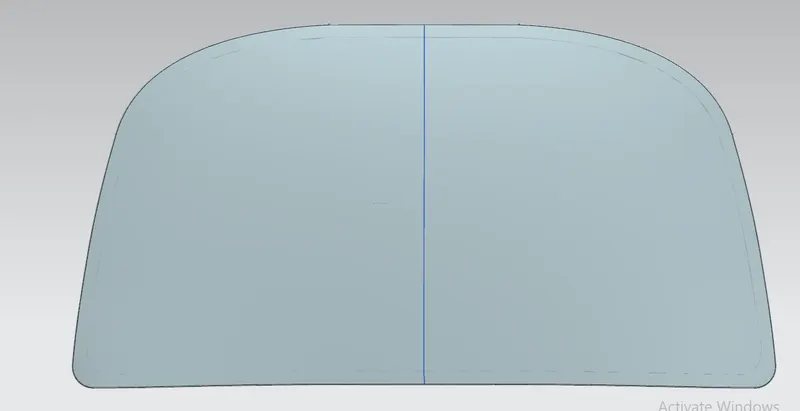
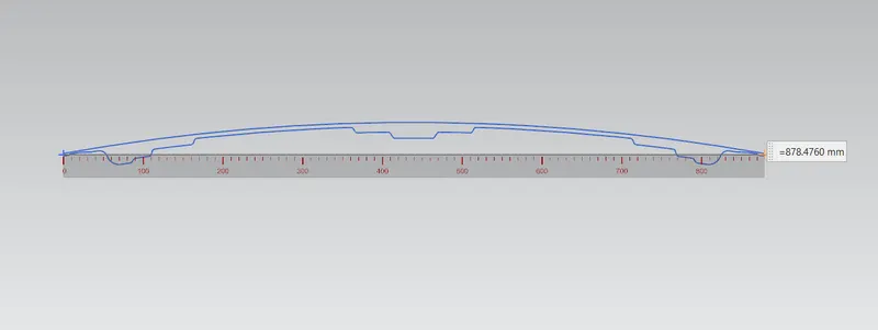
The above figure shows the cross section of the hood in its original state along with the distance between the 2 extreme points of the hood.
Note - The distance Y will be same even after modification in the cross section as the contour will be changed not the end points positions.
We find 2 moment of inertias (minimum and maximum) but we will be taking the minimum moment of inertia in consideration here for the calculation because minimum moment of inertia describes the minimum load the assembly can withstand.
Inertia data for the pre existing section is follows:-
Type : Hollow
CG : (1.702731274, 765.507896071, 0.000000000) [mm]
MOI (max) : 9.245626123e+07 [mm^4]
MOI (min) : 2.850881164e+05 [mm^4]
Principal Directions
Max: (0.002287226, 0.999997384, 0.00000000)
Min: (0.999997384, -0.002287226, 0.00000000)
Section Length : 3.795659874e+03[mm]
Section Area : 1.418872109e+03[mm^2]
Calculation:-
Minimum Moment of Inertia (I) = 2.850881164e+05 [mm^4]
Distance from N.A. (Y) = 439.238 [mm] (since 878.4760/2 = Y)
hence,
Section Modulus S = I/Y
S= 285088.1164/439.238 = 649.05 [mm^3]
So for already existing Cross section the Section Modulus value is 649.05 [mm^3]
Now the design is modified in such a way that
The distance between The Hood Outer panel and the bottom most surface of hood inner panel is 25mm (max) and 5mm (min) and In the existing figure I have created 3 embossed steps of 7, 7 and 6 mm (see above cross section figure)) for that 20 mm range of hood inner pannel.
Now I modified the cross section in such a way that instead of 3 embossed steps i have made 4 embossed steps of 3, 7, 6 and 4mm which has changed the contour of the cross section and will subsequently give a different moment of inertia and ultimately a different Section Modulus.
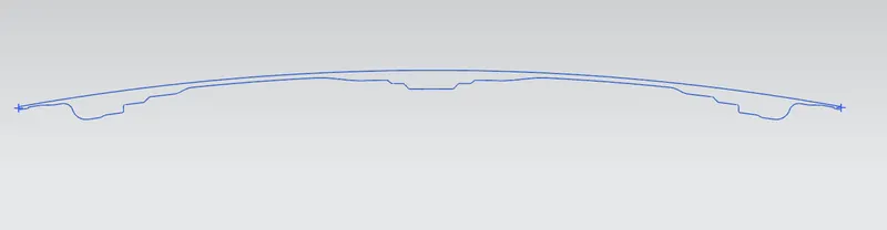
Inertia data for the pre existing section is follows:-
Type : Hollow
CG : (6.146318793, 764835386264, -935.549480826) [mm]
MOI (max) : 9.284288221e+07 [mm^4]
MOI (min) : 2.873989373e+05 [mm^4]
Principal Directions
Max: (0.002103507, 0.999553216, 0.029815146)
Min: (0.999553216, -0.002103507, 0.001182996)
Section Length : 3.757811546e+03[mm]
Section Area : 1.402987153e+03[mm^2]
Value of Moment of Inertia (minimum) found for this new modified cross section is - 3.017104992e+05 [mm^4]
Calculation:-
Minimum Moment of Inertia (I) = 2.8739889373e+05 [mm^4]
Distance from N.A. (Y) = 439.238 [mm] (since 878.4760/2 = Y)
hence,
Section Modulus S = I/Y
S= 287398.8937/439.238 = 654.312 [mm^3]
So for already existing Cross section the Section Modulus value is 654.312 [mm^3]
Conclusion:-
The modified cross section has higher moment of Inertia and higher Section Modulus which means the strength is increased in the hood. As the moment of inertia has increased from 649.05 [mm^3] to 654.312 [mm^3]
There are many ways to increase the moment of inertia such as offsetting all the curves in particular direction or other way like this where i have increased the embossed steps to get an increament in the moment of inertia. Its not necessary that by increasing the no. of embossed steps will always give the higher MOI and Section Modulus. We need to figure this by applying different contours to the cross section. Different contours will give different moment of inertia and we have to check that which contour is giving an increased MOI so that the strength can be considered as increased.