Roof challenge
ROOF
An automobile roof or car top is the portion of an automobile that sits above the passenger compartment, protecting the vehicle occupants from sun, wind, rain, and other external elements.
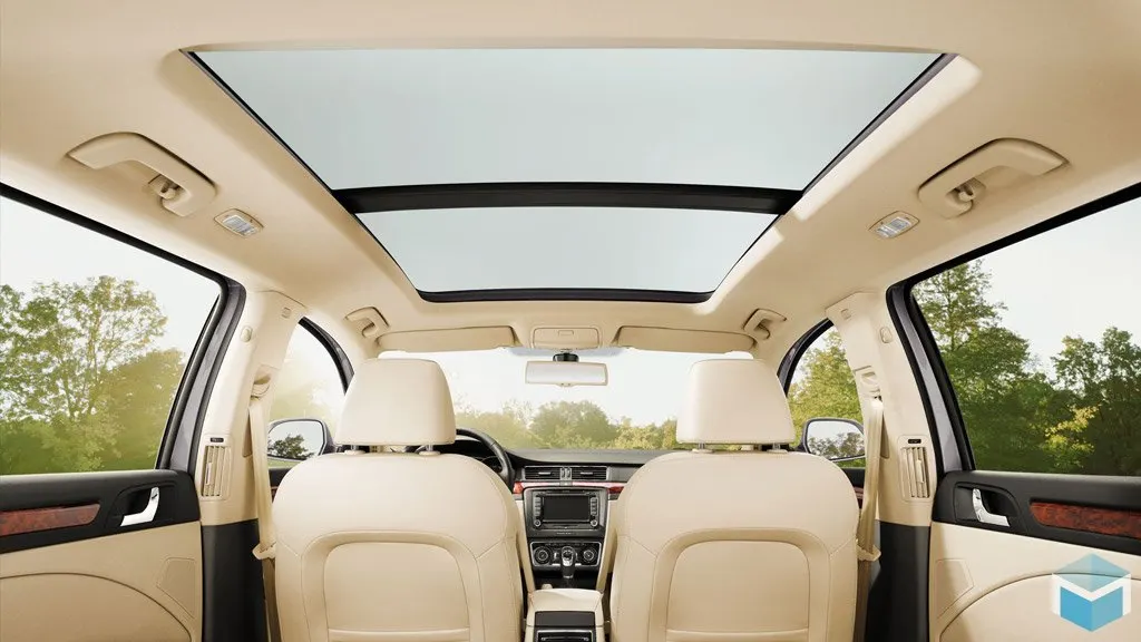
Roof is one of the most important BIW component in a car or any vehicle as it protects the passenger from Direct sunlight, heat, rain and snow etc.
Variartions in Car Roofs :-
1- Convertible
A convertible or cabriolet is a passenger car that can be driven with or without a roof in place. The methods of retracting and storing the roof vary between models. A convertible allows an open-air driving experience, with the ability to provide a roof when required. Potential drawbacks of convertibles are reduced structural rigidity (requiring significant engineering and modification to counteract the effects of removing a car's roof) and cargo space.
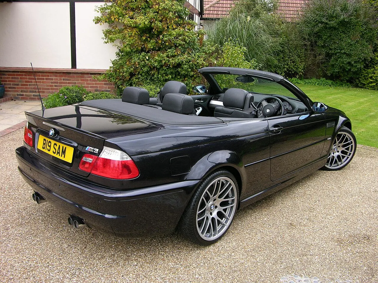
2001 BMW M3 convertible
2- Hardtrop
A hardtop is a rigid form of automobile roof, which for modern cars is typically constructed from metal. A hardtop roof can be either fixed (i.e. not removable), detachable for separate storing or retractable within the vehicle itself.
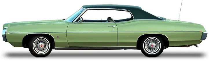
Two-door hardtop coupe: 1969 Pontiac Parisienne
3- Sunroof
A sunroof is a movable panel that opens to uncover a window in an automobile roof, allowing light and/or fresh air to enter the passenger compartment. Sunroofs can be manually operated or motor driven, and are available in many shapes, sizes and styles. While the term sunroof is now used generically to describe any glass panel in the roof, the term "moonroof" was historically used to describe stationary glass panes rigidly mounted in the roof panel over the passenger compartment.
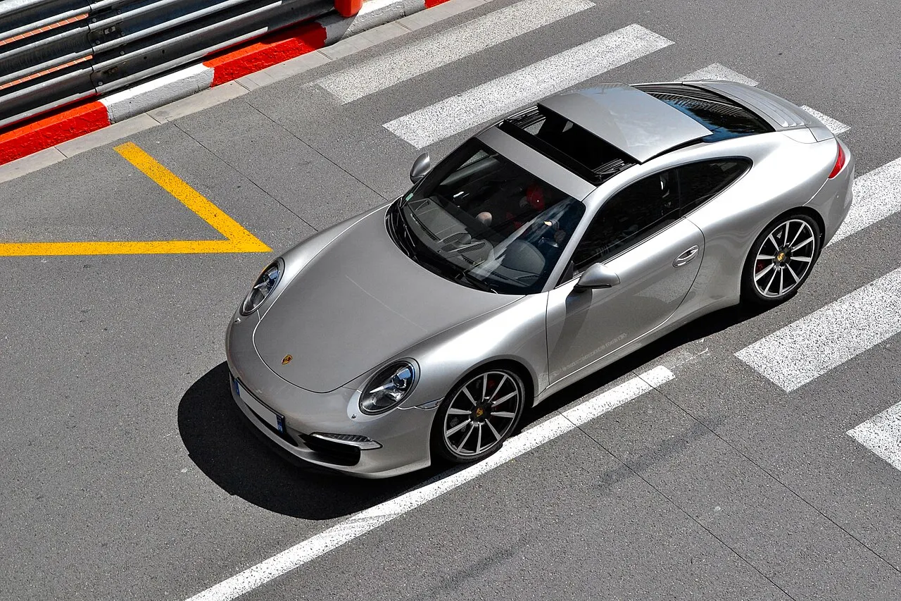
A sliding sunroof on a Porsche 911 Carrera (Type 991)
Material Used For Roof :-
Steel has been the metal which has been used extensively for the BIW components over the years. Apart from steel The use of aluminium for the car roof is well established in all-aluminium car body designs. But there are also significant aluminium applications in the roof of vehicles with steel car body structures. Weight reduction in the roof (i.e. lowering the centre of gravity)has always been a high priority topic in automotive design. However, the roof is generally anintegral part of the body-in-white. Therefore, the integration of structural aluminium components into the roof of a steel body structure requires an in-depth consideration of different aspects.
The substitution of the steel roof panel by a lightweight aluminium alloy roof panel is an attractive option to optimize the mass distribution in a car. However, if the remainder of the vehicle body structure continues to be fabricated in steel, two major hurdles have to be overcome. The first problem is the realization of a reliable joint between the different materials. Various technologies have been developed to join aluminium to steel; in most cases, adhesive bonding combined with a mechanical joining technique is applied, but also friction stir welding, soldering or fusion welding methods have been developed. If the mixed material joint is properly protected to avoid any danger of galvanic corrosion, a safe and durable joint is achieved. The other problem is the different thermal expansion coefficient of aluminium and steel. The combination of the aluminium alloy roof attached to the steel body may create compressive stresses in the aluminium roof when the body is subjected to elevated temperatures such as those required to cure the paint applied to the assembled body-in-white. Visible thermal distortions of the roof panel, if any, are not acceptable. Such effects can be eliminated (orminimized) for example by the use of an aluminium alloy with a higher strength level, the selection of an appropriate adhesive, the application of proper joining procedures (e.g. optimized riveting position and use of jigs) as well as other suitable measures.
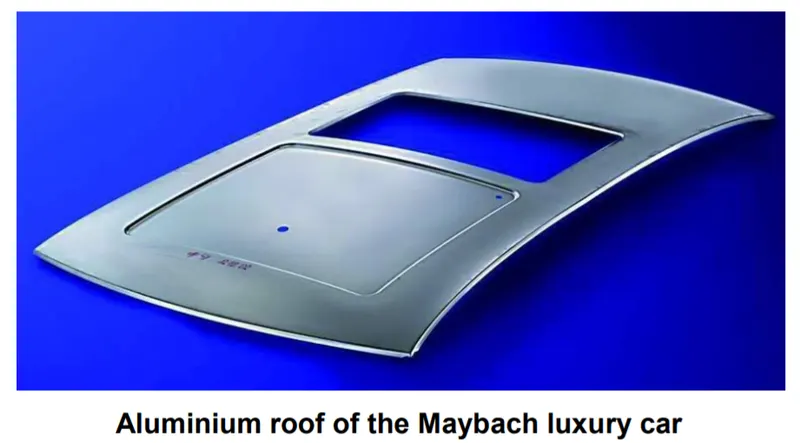
An aluminium roof on a steel body structure is also found on the Range Rover Evoque (L538) which was introduced into the market in 2012. The use of aluminium for the bonnet and the roof, thermoplastic fenders and a polymeric composite, one-piece tailgate helped to produce a vehicle weighing 100 kg less than the steel Freelander.
A roof should be such that it can withstand the load over it. Sometimes the luggage needs to be carried over the roof. Also in case of accident or accidental situation it should be protrecting the humans inside by either withstanding the load or else act as a barrier between passenger and unwanted stuff. Roof is not completely flat. It have a curvy surface but the radius of curvature is not constant throughout its length and width as it varies due to specific reasons. A curvy surface has higher strength than a flat surface. But a roof can't be made with a big radius of curvature throughout for obvious reasons such as the visual appearance, height of the car and its capability to carry luggage over etc do not allow it to have a big curvature radius.. So there are regions on the car roof when its close to flat i.e. having a small radius of curvature comparatively. So at those flatter regions the strength is less. To compensate for that strength BOW ROOFS and CENTER REINFORCEMENT are introduced in the car at the roof ceiling region i.e. At the bottom of roof surface. Roof also have front and rear rails which are described further along with their images.
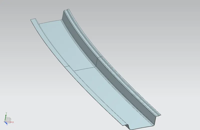
- Front Roof Rail :- It is the part which acts as a junction between the roof and the car body as Front roof rail attaches with the roof by Mastics and also attaches with the car body parts such as Body side outer, Windshield. It is generally offsetted by a fix distance from car roof, its depth? distance from roof outer panel depends upon the visual clearance for the driver and passenger. In our case it is 32mm. The Mastics are applied between Flanges of Front Roof rail and the ditch area Of Roof Outer Panel in front position. Minimum angle of 3 degree needs to be given for the drawing purpose.
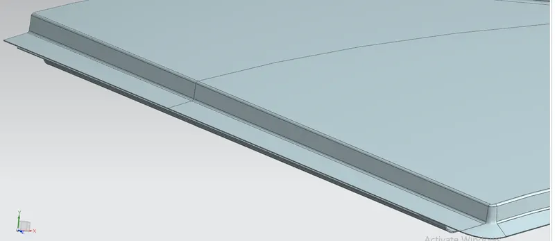
- Ditch Area:- It is that region of car which is act as an extention from roof outer panel at some angles to facilitate the perfect joining of roof outer panel with other car body parts such as the A, B, C and D (if present) pillars of car.. Also Ditch area gives a good appearance to car. The ditch area can be clearly seen in the below picture. It surround the car Roof outer panel .
- Bow Roof :- Bow Roofs are used for improving the strength of Roof assembly and are generally placed below the flatter region of the roof. The no. of the Bow Roofs depend upon many factors such as length of the car. Magnitude of strength needs to be increased. Smaller cars have less no. of Bow Roofs. Positioning of Bow Roof is a very important consideration and depends upon the "Heat Distortion" and "Snow Load" Criterias. I have created 2 Bow Roofs which will be joined by the help of Mastic sealants and may be spot welded with the ditch area. Draft is necessary here as well for facilitating the drawing operation. Here are the images of 2 bow roofs which have different contours at their exterior flanges. Some sheet metal can be trimmed for weight reduction purpose.
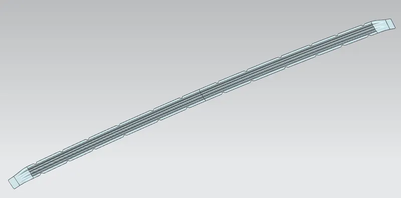
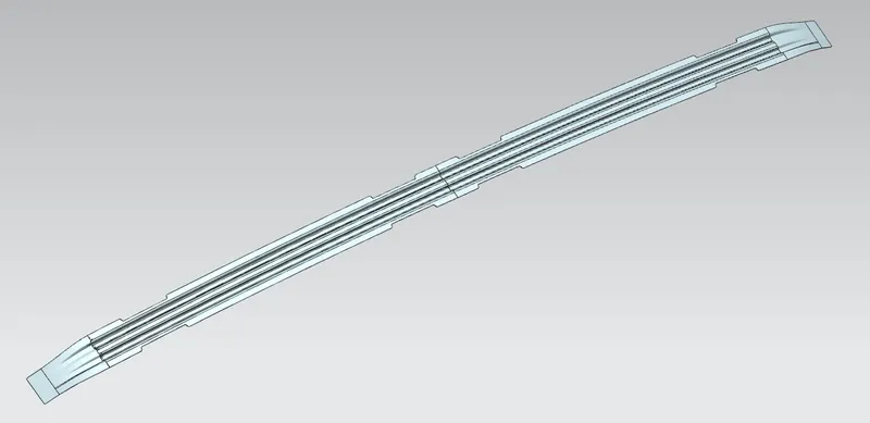
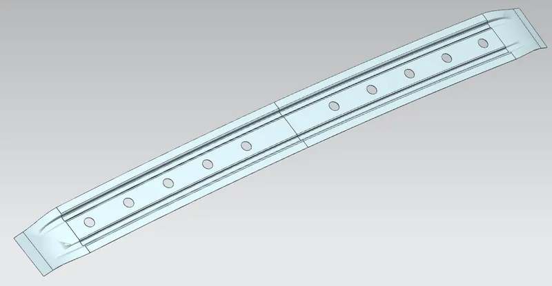
- Center Reinforcement Rail:- It is similar to bow roofs but has a wider span and generally mounted in the mid region of the car roof. Like Bow Roofs it is also joined with roof by Mastic Sealants and spot welded with ditch region. Draft angle for drawing purpose is given here as well. I have created holes in my center Reinforcement rail for weight reduction purpose. Head Room Clearance is also a criteria associated with the positioning and depth of center roof rail and bow roofs apart form the heat distortion and snow load criteria.
- Rear Roof Rail:- Just like front roof rail the rear roof rail of the roof assembly is attached with the ditch area of roof outer panel at the rear end of the car, also attaches the Back door. Its design depends largely on the opening and closing condition of the back door that whether the upper edge of backdoor goes inside the roof or outside while the back door opens to its full angle.
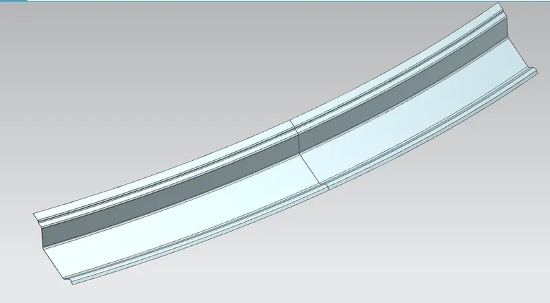
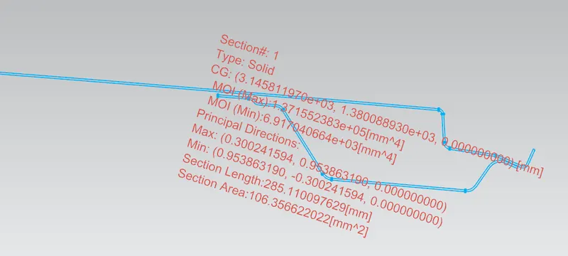
Images of Section Inertia Analysis of FRONT ROOF RAIL, BOW ROOF 1 , CENTER ROOF RAIL, BOW ROOF 2 and REAL ROOF RAIL respectively.
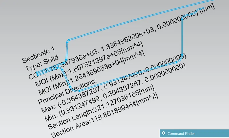
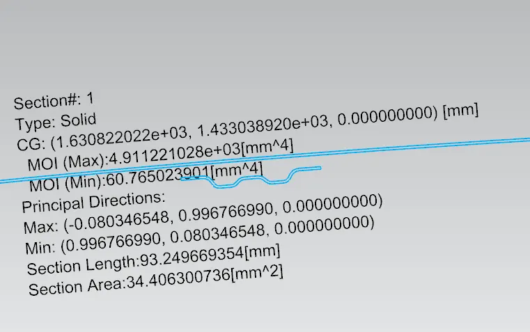
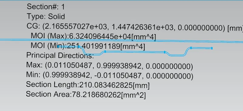
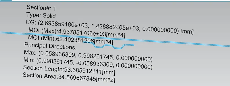
- Heat Distortion Criteria:- Due to exposure to high temperatures for a relatively longer duration of time, the Roof outer panel of car may start distorting. The roof may tend to cave in due to this. In order to avoid such a situation arrangements are made up in roof assembly but those arrangements are done only after some calculation and analysis.
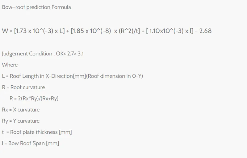
If Value of W is less than 2.7 it will be pass the requirement but not if it exceeds 3.5
| S. No. | Bows | Rx | Ry | R | l | L | t | W | OK/NG |
| 1 | FRR to BR 1 | 2487.37 | 5752.04 | 3472.85 | 37.50 | 2033.705 | 0.75 | 1.54335 | OK |
| 2 | BR 1 to CRR | 6054.44 | 5010.85 | 5483.43 | 465 | 2033.705 | 0.75 | 2.0915 | OK |
| 3 | CRR to BR2 | 10675.13 | 3037.88 | 4729.72 | 459 | 2033.705 | 0.75 | 1.895 | OK |
| 4 | BR2 to RRR | 14794.11 | 3252.694 | 5332.87 | 372 | 2033.705 | 0.75 | 1.949 | OK |
All 4 regions are passing the Heat Distortion criteria as the value of W is less than 2.7 in all 4 cases which is OK.
- Snow Load Criteria:- In Countries where there are snow falls there arise one more strength criteria which needs to be fullfilled such that when a car is parked in an open area for several days and due to snow fall the snow gets accumulated on the roof which almost acts as a dead weight so the roof is prone to cave in. So to prevent this arrangements are done based on formula and calculations.
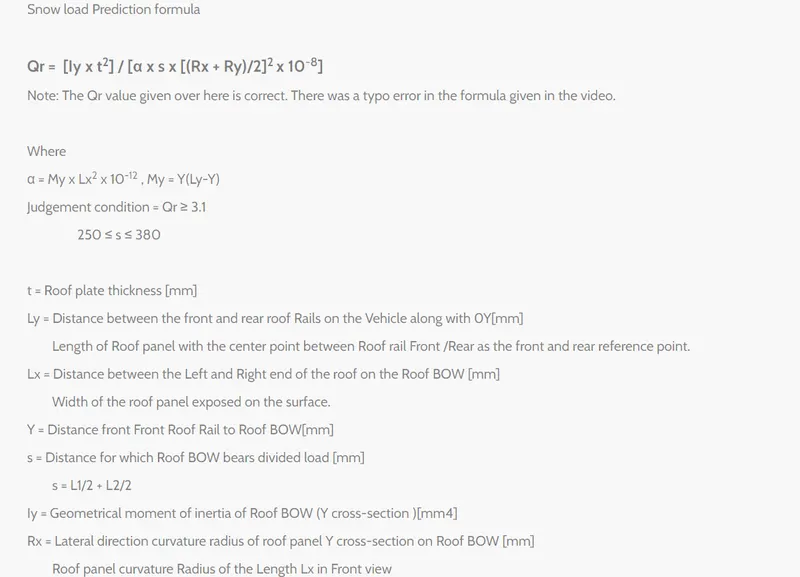
| S. No. | Bows | Rx | Ry | Iy | Alpha | Lx | Ly | s | y | t | Qr | Determination (Qr) |
| 1 | FRR to BR 1 | 2553.02 | 3391.38 | 60.77 | 0.85 | 1140.52 | 1909.70 | 494.5 | 454 | 0.75 | 0.92 | NG |
| 2 | BR 1 to CRR | 4113.91 | 2932.37 | 251.40 | 0.87 | 1090.12 | 1909.70 | 532 | 535 | 0.75 | 2.46 | NG |
| 3 | CRR to BR2 | 16157.10 | 6341.13 | 62.4 | 0.82 | 1059341 | 1909.70 | 491.75 | 529 | 0.75 | 0.063 | NG |
| 4 | BR2 to RRR | 6831.16 | 5627.10 | 0.72 | 1046.65 | 1909.70 | 227.5 | 454.5 | 0.75 |
What if NG?
In our case the design and arrangements of our bow roofs and center reinforcement rails have failed to pass the snow load criteria. But there are Some workaround 2 of such i have implemented as traial and error and let's observe that whether they help or not
First is by increasing the thickness of bow roofs and center reinforcement rail which will subsequently increase the moment of inertia and Qr will be increased in our case i only had the margin to increase it by 0.2 mm to make it 0.95 mm thick bow roofs and center reinforcement rail.
So after increasing the thickness to 0.95mm the results were as follows:-
| S. No. | Bows | Rx | Ry | Iy | Alpha | Lx | Ly | s | y | t | Qr | Determination (Qr) |
| 1 | FRR to BR 1 | 2553.02 | 3391.38 | 60.77 | 0.85 | 1140.52 | 1909.70 | 494.5 | 454 | 0.95 | 1.8987 | NG |
| 2 | BR 1 to CRR | 4113.91 | 2932.37 | 251.40 | 0.87 | 1090.12 | 1909.70 | 532 | 535 | 0.95 | 5.04 | Ok |
| 3 | CRR to BR2 | 16157.10 | 6341.13 | 62.4 | 0.82 | 1059341 | 1909.70 | 491.75 | 529 | 0.95 | 0.13 | NG |
| 4 | BR2 to RRR | 6831.16 | 5627.10 | 0.72 | 1046.65 | 1909.70 | 227.5 | 454.5 | 0.95 |
So after increasing the thickness the mid region that is BR1 to CRR is ppassing the snow load criteria but other regions are not still satisfying the requirement. So in such cases we can create embosses over the roof outer panel.
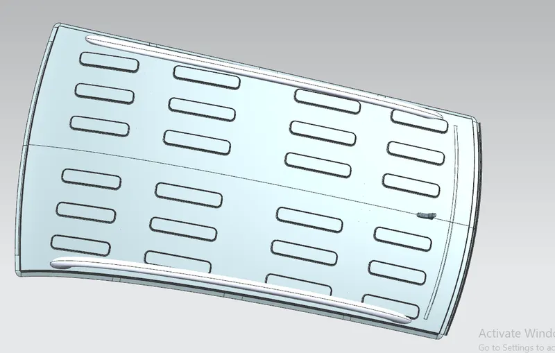
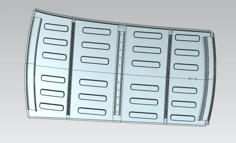
Embosses will increase the strength of the car roof drastically as embossed surface will have a higher moment of inertia. Although Long embosses can be given on the roof surface but i have given separate embosses ehich are not passing exactly above to any Bow roof or Center roof rail. So that we can have more surface to surface contact for Application of mastic sealants in between which will add the strength as well.
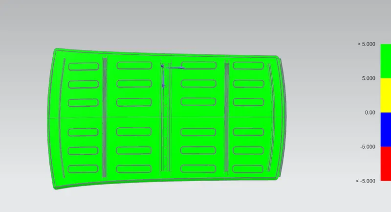
Draft Analysis
The Draft Analysis command enables us to detect if the part we drafted will be easily removed. This type of analysis is performed based on color ranges identifying zones on the analyzed element where the deviation from the draft direction at any point, corresponds to specified values.