Section Modulus calculation and optimization
Aim: To calculate the section modulus of previously designed Hood panel and to make changes to the hood section to obtain a better section modulus.
Description:
This project is completed using Siemens NX 12 software.
Moment of Inertia:
The tendency of a body to resist angular acceleration, expressed as the sum of the products of the mass of each particle in the body and the square of its perpendicular distance from the axis of rotation.
Or in more simple terms, it can be described as a quantity that decides the amount of torque needed for a specific angular acceleration in a rotational axis. Moment of Inertia is also known as the angular mass or rotational inertia.
The SI unit of moment of inertia is kg m2.
Mathematically,
I = m x r2
Where, m = Sum of the product of the mass.
r = Distance from the axis of the rotation.
Section modulus:
Section Modulus is the geometric property of the given cross-section of any shaft or beam structures. It is the direct measure of the strength of the shaft section or the beam section. Higher the section modulus of a structure, the more the resistive it becomes to bending.
Mathematically,
S=I/y
I= Moment of Inertia
y= Distance from neutral axis to outer fibre.
Procedure:
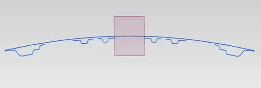
1. Obtain the cross-section of the hood panel (both inner & outer panel.
First create a datum plane at the centre of the hood and using the option ‘Intersection curve’ we get the cross-section of the hood panel.
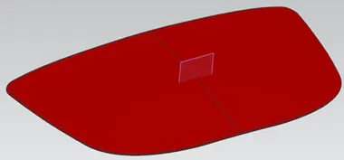 |
| Hood panel with datum plane at the centre. |
2. To perform the ‘Section inertia analysis’ we need to have a closed surface. So, we enter the sketcher work bench and opt only the required curves (outer curve/fibre of inner hood panel and outer hood panel) and gaps are covered using ‘Studio spline’ option. Finally, trim out the extra portion and we have a closed fibre (Cross-section).
 |
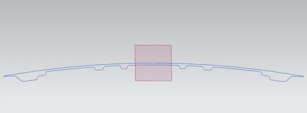 |
| Cross-section of the hood panel. | Closed profile for performing the section inertia analysis. |
3. Exit the sketch work bench, and opt ‘Section inertia modulus’ now select the sketch and press Ok.
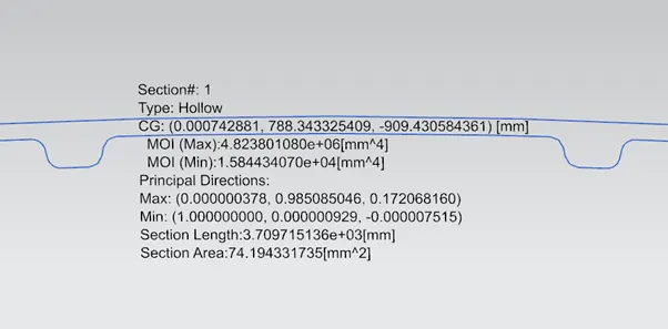
I got the following details of the cross-section as shown in below image.
 |
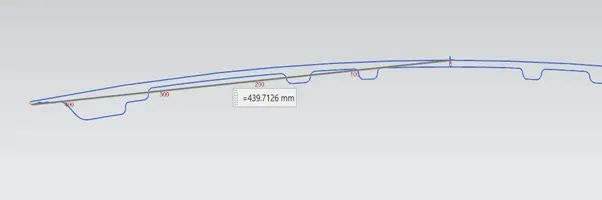 |
| Result of Section inertia analysis on the hood panel. | Distance from centre of the hood panel to extreme end. |
Perform the calculation for section modulus,
We consider the MOI (Min) to understand what is the
MOI (Max) = 4.823801080 x 106 mm4
MOI (Min) = 1.584434070 x 104 mm4
Y = 439.7126 mm
SMax = 4.823801080 x 10⁶ / 349.7126 = 13793.615 mm3
SMin = 1.584434070 x 10⁴ / 349.7126 = 35.659 mm3
4. Now we need to make some changes in hood design for better section modulus results, w.k.t to have a better section modulus we need to have a good M.O.I(min) for which the cross-section of the panel should be increased. So, I’ve offset the outer fibre of the inner hood panel in outward direction to 0.5mm distance. Finally, perform the section inertia modulus analysis and following data as shown in figure are received.
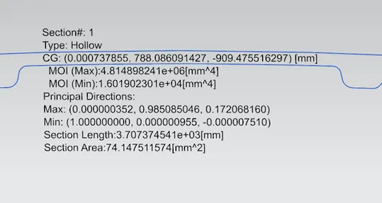 |
| Result of Section inertia analysis on optimized hood panel. |
For which I got the following result,
MOI (Max) = 4.81489824 x 106 mm4
MOI (Min) = 1.601902301 x 104 mm4
Y = 439.7126 mm.
SMax = 4.81489824 x 10⁶ / 349.7126 = 13768.157 mm3
SMin = 1.601902301 x 10⁴ / 349.7126 = 36.430 mm3
Conclusion:
- The section modulus of the new cross-section is greater than the previous one, so according to the results obtained it is clear that the resistance against bending of the new cross-section is more.
- There is about 2% increase in Section modulus of the optimized hood panel.