Section Modulus calculation and optimization
AIM:
To find the section modulus of the hood and optimization to improve the overall section modulus.
Objective:
Use the section from your hood design and calculate the section modulus using the formula S=I/Y.
Section Modulus:
The section modulus is the geometry property of the cross-section used for designing beams and flexural members. It does not represent anything physically.
Formula of Section Modulus: It is defined as the ratio of the total moment resisted by the section to the stress in the extreme fiber which is equal to yield stress.
Which is equal to yield stress.
Therefore,
S=I/Y, Where
S= Section Modulus(unit = mm^3)
I= Moment of Inertia of the section to the stress in the extreme end of the object(mm^4)
Y= Distance between the neutral axis and extreme end of the object(mm).
Moment of Inertia: It is defined as the quantity expressed by the body resisting angular acceleration which is the sum of the product of the mass of every particle with its square of a distance from the axis of rotation, or in more simple terms, it can be described as a quantity that decides the amount of torque needed for a specific angular acceleration in a rotational axis. Moment of inertia is also known as the angular mass or rotational inertia. The SI unit of moment of inertia is kg m^2.
Moment of inertia is usually specified with respect to a chosen axis of rotation. It mainly depends on the the distribution of mass around an axis of rotation. MOI varies depending on the axis that is chosen.
In General Form,
Moment of Inertia is expressed as I = m x r^2
Where,
m = Sum of the product of the mass.
r = Distance from the axis of the rotation.
Area Moment Of Inertia:
The area moment of inertia of a beam cross-section area measures the beam ability to resist bending. The larger the moment of inertia less will be the bend.
Where,
M= Bending Moment
I = Area Moment of Inertia
E = Young Modulus
R = Radius of gyration
Neutral Axis: When beam is subjected to pure bending the topmost fibers of the beam are subjected to maximum compression, while the bottom-most fiber of the beams are subjected to maximum tension.
This picture contains the following scene, a diagram of a beam on its narrow edge supported at both ends. A man is walking on a straight beam. Diagram of abeam resting on its flat side supported at both ends. A man is walking on a straight beam and it is bending in the middle.
Calculation:
Section Modulus:
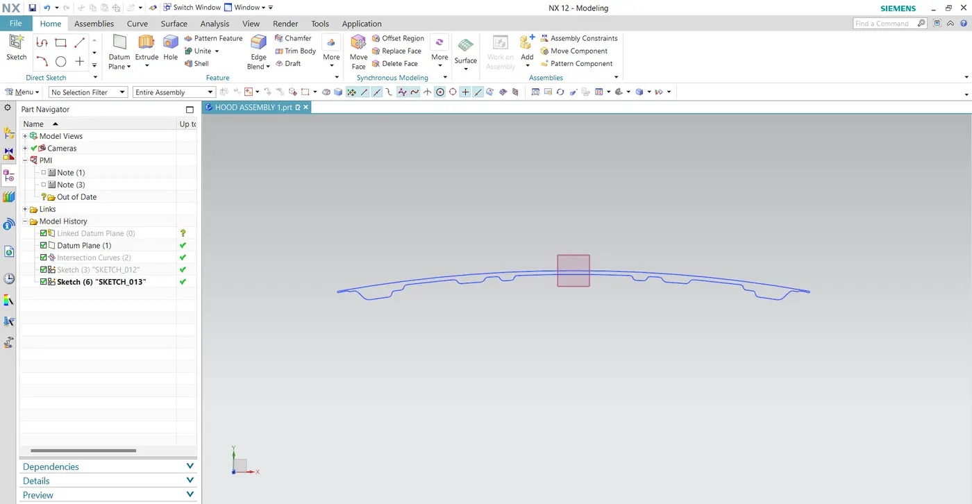
We going to calculate the inertia from the front, we can also calculate from the side by selecting according to need.
Case 1:
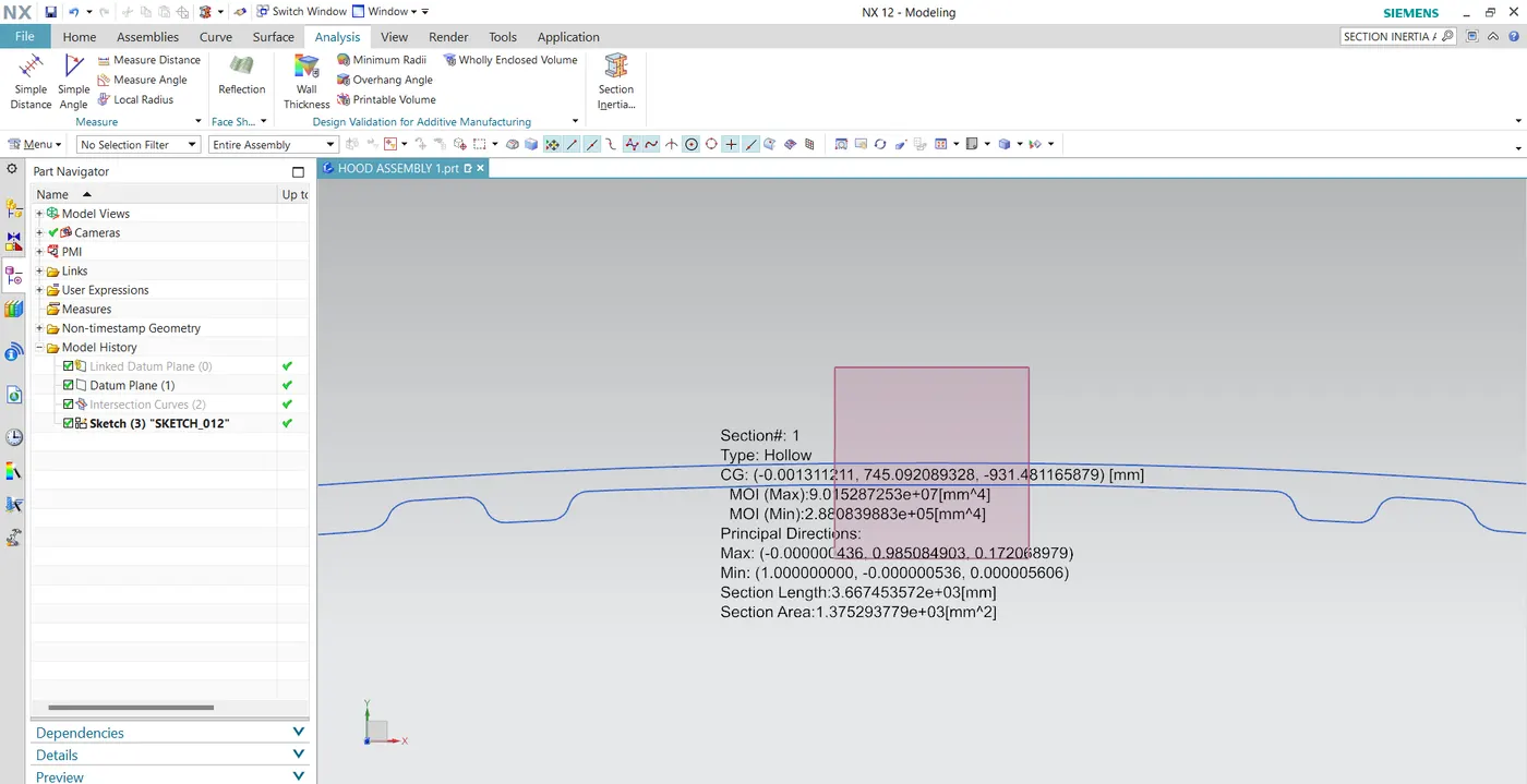
Here we considered the inner panel section to analyze the section inertia analysis after doing this we got the following result as shown in the above image:
I (MAX) = 9.015287253e+07[mm^4]
I (MIN) = 2.880839883e+05[mm^4]
As per section modulus equation,
S =I/Y
I = MOI (min) Value is considered
Y = Total Distance / 2
Y =876.4623/2
Y = 438.23
Therefore,
S = 288083.9883/438.23
S1 = 657.38080 mm^3
Case 2:
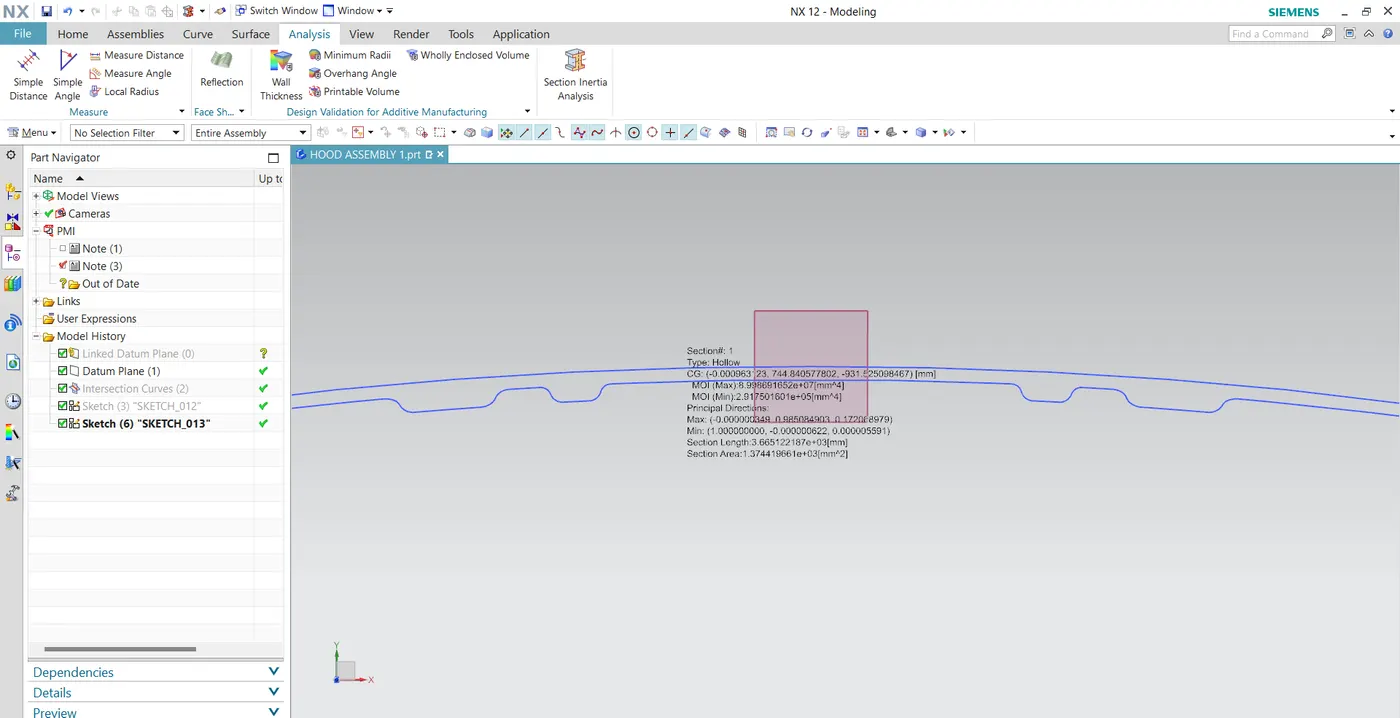
Here we considered a section of the inner panel after offsetting it to 0.5 value and then we done the analyze on it, the above image is the desired result we got.
I (MAX) = 8.998691652e+07[mm^4]
I (MIN) = 2.917501601e+05[mm^4]
As per section modulus equation,
S =I/Y
I = MOI (min) Value is considered
Y = Total Distance / 2
Y =876.4623/2
Y = 438.23
Therefore,
S = 291750.1601/438.23
S2 = 665.74666mm^3
Results:
After the calculation of the above 2 cases the section modulus of S1 and S2 the difference is 8.36586mm.
The section modulus value of case 2 is higher than that case 1.
As we increase the section area, moment of inertia & section modulus increase which means strength and load material also increase. The moment of inertia is directly proportional to the strength of the material.