Section Modulus calculation and optimization
Section modulus calculation and optimization.
Aim :Determine the moment of inertia of the created hood and optimized hood and compare both.
Section modulus is a geometric property for a given cross-section used in the design of beams or flexural members .Other geometric properties used in the design include an area for tension and shear , the radius of gyration for compression , and the moment of inertia and polar moment of inertia for stiffness .Any relationship between these properties is highly dependent onthe shape in question.Equations for the section modulus of common shapes are given below .There are two type of modulus 1)Elastic section modulus 2)Plastic section modulus .The section modulus of different profiles can also be found as numerical values for common profiles in tables listing properties of such.
Use the section from the hood design and calculate the section modulus using the formula
S=I/y
s= section modulus
I= moment of inertia
y=distance between the neutral axis and the extreme end of the object
come up with a new section that has improved the section modulus of the previous section and mention what change made that has increased the strength .
Elastic section modulus:
For general design the elastic section modulus is used applying up to the yield point for most metals and other common material.
The elastic section modulus is defined as S = I / y, where I is the secondmoment of area (or area moment of inertia, not to be confused with moment of inertia) and y is the distance from the neutral axis to any given fibre. It is often reported using y = c, where c is the distance from the neutral axis to the most extreme fibre, as seen in the table below. It is also often used to determine the yield moment (My) such that My = S ⋅ σy, where σy is the yield strength of the material
| Cross-sectional shape | Figure | Equation | Comment |
|---|---|---|---|
| Rectangle | �=�ℎ26 |
Solid arrow represents neutral axis | |
| doubly symmetric I-section (major axis) | ��=��26−�ℎ36�
��=��� with �=�2 |
NA indicates neutral axis | |
| doubly symmetric I-section (minor axis) | ��=�2(�−ℎ)6+(�−�)3ℎ6� [4] [4] |
NA indicates neutral axis | |
| Circle | �=��332 [3] [3] |
Solid arrow represents neutral axis | |
| Circular hollow section | �=�(�24−�14)4�2=�(�24−�14)32�2 |
Solid arrow represents neutral axis | |
| Rectangular hollow section | �=��26−�ℎ36� |
NA indicates neutral axis | |
| Diamond | �=��224 |
NA indicates neutral axis | |
| C-channel | �=��26−�ℎ36� |
NA indicates neutral axis |
 ,
,
Plastic section modulus :
The plastic section modulus is used for materials where elastic yielding is acceptable and plastic behavior is assumed to be an acceptable limit. Designs generally strive to ultimately remain below the plastic limit to avoid permanent deformations, often comparing the plastic capacity against amplified forces or stresses.
The plastic section modulus depends on the location of the plastic neutral axis (PNA).The PNA is defined as the axis that splits the cross section such that the compression force from the area in compression equals the tension force from the area in tension. So, for sections with constant, and equal compressive and tensile yielding stress, the area above and below the PNA will be equal, but for composite sections, this is not necessarily the case.
The plastic section modulus is the sum of the areas of the cross section on each side of the PNA (which may or may not be equal) multiplied by the distance from the local centroids of the two areas to the PNA:
��=����+����
The plastic section modulus is used to calculate the plastic moment, Mp, or full capacity of a cross-section. The two terms are related by the yield strength of the material in question, Fy, by Mp = Fy ⋅ Z. Plastic section modulus and elastic section modulus are related by a shape factor which can be denoted by k, used for an indication of capacity beyond elastic limit of material. This could be shown mathematically with the formula :-
�=��
Moment of inertia:
The moment of inertia, otherwise known as the mass moment of inertia, angular mass, second moment of mass, or most accurately, rotational inertia, of a rigid body is a quantity that determines the torque needed for a desired angular acceleration about a rotational axis, akin to how mass determines the force needed for a desired acceleration. It depends on the body's mass distribution and the axis chosen, with larger moments requiring more torque to change the body's rate of rotation.

I =moment of inertia
L=Angular momentum.
ω = Angular velocity
SI unit:kg·m2
pound-foot-second squared in imperial or us units=lbf·ft·s2
Dimension :
M L2
For different shapes
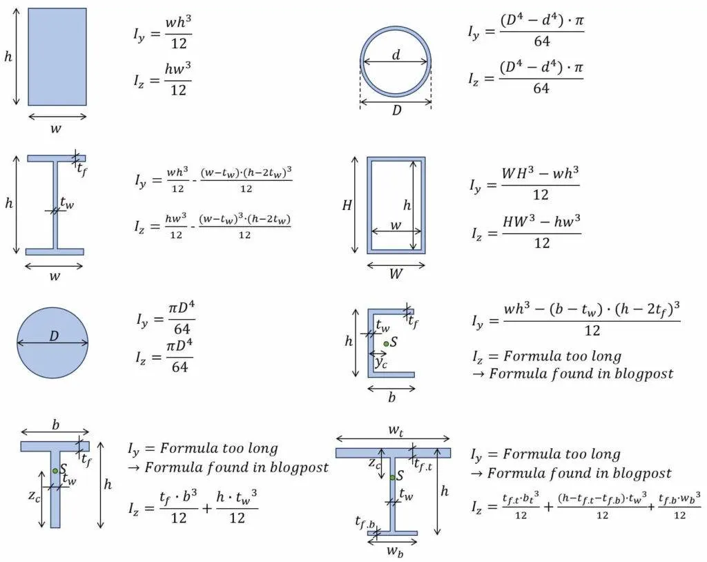
Section modulus calculation and optimization
Hood design:
Process:
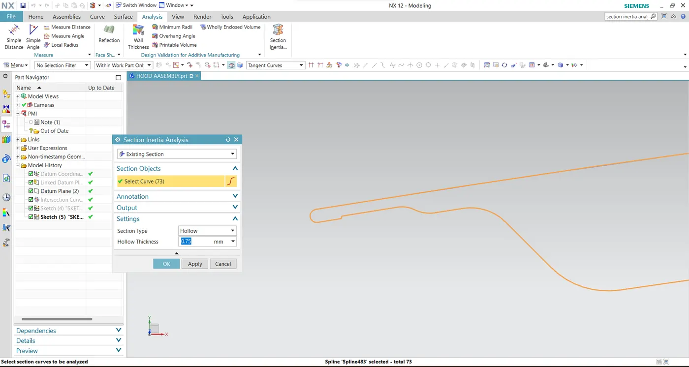
- Select a datum plane use on curve to create a plane on the surface.
- Use intersection curve command to intersect a surface to do a section modulus analaysis.
- select a sketch and project the intersection curve and hide the intersectiona curve than fil the gaps with studio line .
- Do the section inertia analaysis on the diagram with the hollow thickness of 0.75mm and done the analaysis .
- from the analysis MOI values to be noted and then calculated with the section modulus M =i /y.
- So next we optimized the hood to deternine to check strength of inner panel increase the length of 0.5mm offset to inner panel .
- project the offset and connect the gaps with studio line and join with upper cross section and did the section inertia analaysis .
- Finally compare the both design and calculations strength was increased.
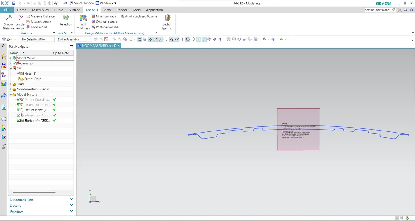
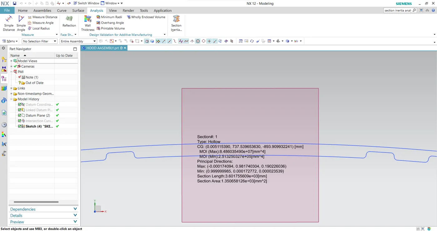
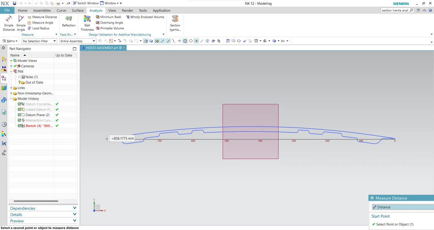
Moment of inertia (MOI),Imax= 8.486035490x10^7 [mm^4]
Moment of inertia (MOI),Imax= 2.513250327x10^5[mm^4]
Distance betweenthe neutral axis and the extreme end of the object, y = 858.1775 mm / 2 =429.088 mm
section modulus ,S= moment of inertia (MOi) ,I / Distance between the neutral axis and the extreme end of the object.(y)
For Maximum (MOI) ,
S= (8.486035490x10^7 mm^4) / (429.088mm)
Smax=19.7769117057x10^4mm^3
For Minimum (MOI).
s=(2.513250327x10^5 mm^4) / (429.088mm)
Smin=58.57mm^3
Hood optimized Design:
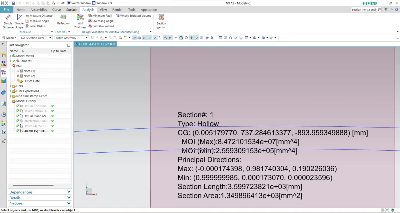
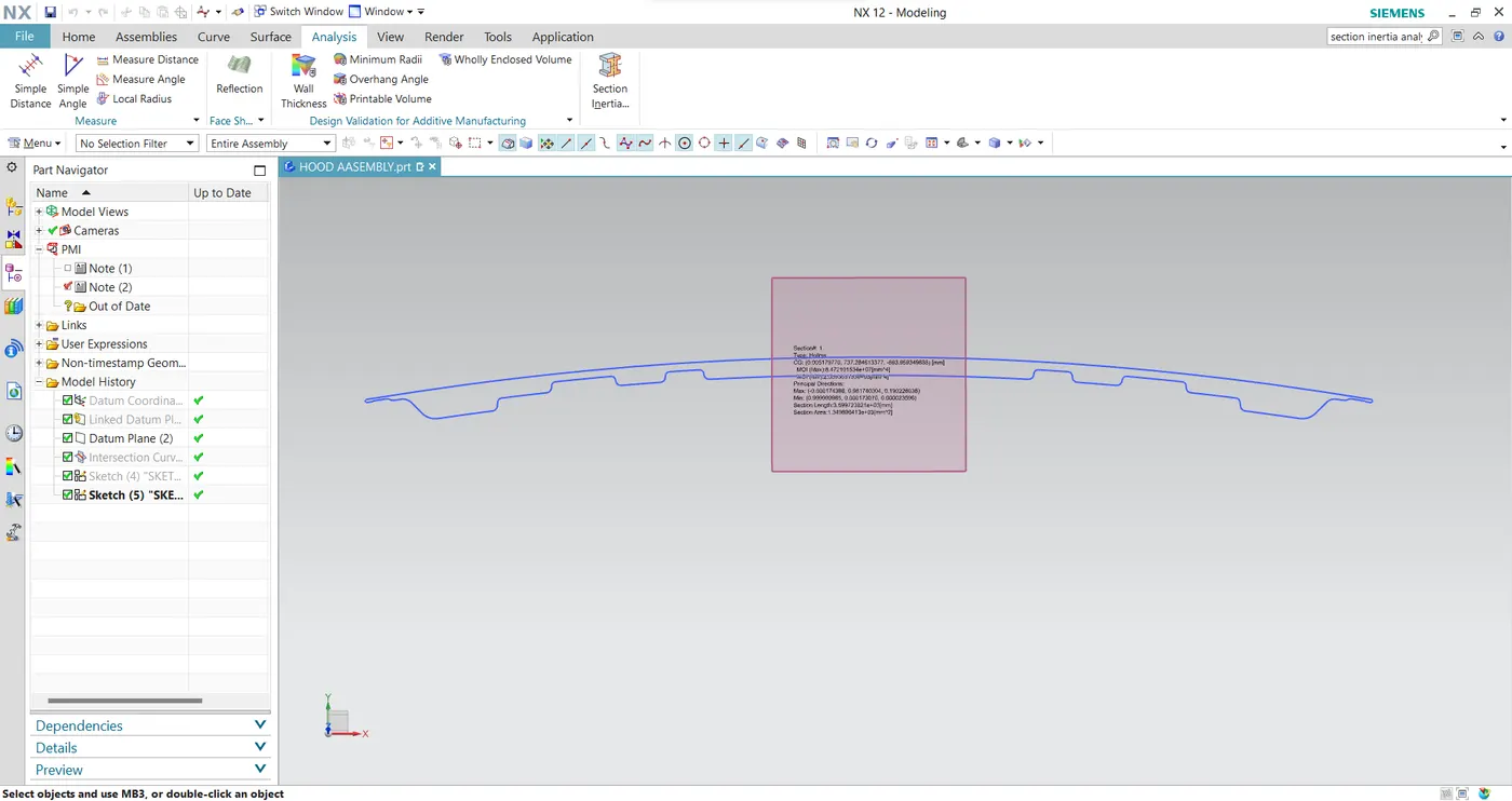
Moment of inertia (MOI),Imax=8.472101534x10^7[mm^4]
Moment of inertia (MOI),Imax=2.559309153x10^5[mm^4]
Distance betweenthe neutral axis and the extreme end of the object, y = 858.1775 mm / 2 =429.088 mm
section modulus ,S= moment of inertia (MOi) ,I / Distance between the neutral axis and the extreme end of the object.(y)
For Maximum (MOI) ,
S= (8.472101534x10^7[mm^4]) / (429.088 mm)
Smax=19.7444382830x10^4 mm^3
For Minimum (MOI).
s= (2.559309153x10^5[mm^4] ) / (429.088 mm)
Smin= 59.64mm^3
Conclusion:
Moment of inertia and section modulus are succesfully calculated and compared with the optimized model. When we increase the cross section area of the hood moment of inertia and section modulus increased. So , strength also increased.we have concluded that while we offsetting the inner panel at 0.5mm down side(optimized). we get result better than the previous model.