Section Modulus calculation and optimization
Section Modulus is a geometric property used to calculate the bending stresses in a structural member. Mathematically, It is defined as the ratio of the moment of inertia of a section about its centroidal axis and to the distance of the extreme layer from the neutral axis.
Where,
S = Section Modulus
I = Moment of Inertia
y = distance between the neutral axis and the extreme end of the object
Other geometric properties used in design include area for tension and shear, radius of gyration for compression, and second moment of area and polar second moment of area for stiffness. Any relationship between these properties is highly dependent on the shape in question.
There are two types of section moduli, the elastic section modulus and the plastic section modulus.
ELASTIC SECTION MODULUS
Elastic section modulus is calculated when we are to use the material behavior till the yield point. For general design purposes, we use elastic section modulus.
The elastic section modulus is defined as S = I / y, where I is the second momemnt of inertia (or area moment of inertia) and y or c is the distance from the neutral axis to any given fibre. It is also often used to determine the yield moment (My) such that My = S ⋅ σy, where σy is the yield strength of the material.
The elastic section modulus of different shapes is as shown.
| S.NO. | SHAPE | MOMENT OF INERTIA | Y max | SECTION MODULUS |
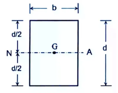
| 1. |
Rectangular section |
I = bd³/12 | ymax = d/2 | S = I/ymax
S = (bd³/12)/(d/2)
S = bd²/6
|
| 2. |
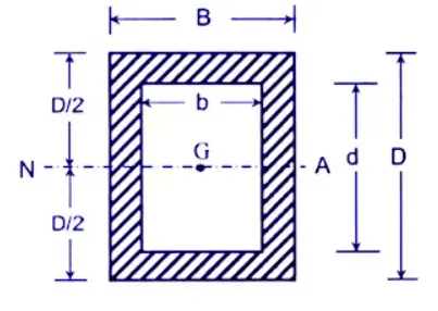
Hollow Rectangular section
|
I = (BD³/12) - (bd³/12) | ymax = D/2 |
S = I/ymax
= (BD³/12) - (bd³/12)/(D/2)
S = (BD³ - bd³)/6D
|
| 3. |
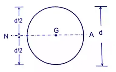
Solid Circular section
|
I = (π/64) × d⁴ | ymax = d/2 |
S = {(π/64) × d⁴}/(d/2)
S = (π/32) × d³
|
| 4. |
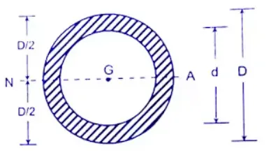
Hollow Circular section
|
I = (π/64) × (D⁴ - d⁴) | ymax = D/2 |
S = (π/64) × (D⁴ - d⁴)/(D/2)
S = π/32 × {(D⁴ - d⁴)/D}
|
| 5. |
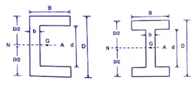
Symmetric I & C section
|
I = (BD³/12) - {(B - b)d³}/12 | ymax = D/2 |
S = [(BD³/12) - {(B - b)d³}/12]/(D/2)
S = {BD³ - (B - b)d³}/6D
|
| 6. |
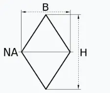
Diamond
|
S = bd²/24
|
PLASTIC SECTION MODULUS
| S. NO. | SHAPE | A(c) and A (t) | SECTION MODULUS |
| 1. |
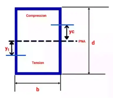
Rectangular section
|
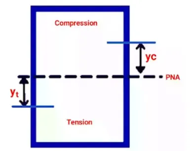
On neutral axis,
Ac = Aₜ and yc = yₜ
Ac = Aₜ = bd/2
yc = yₜ = d/4
|
Zₚ = (Ac × yc) + (Aₜ + yₜ)
Zₚ = (bd/2 × d/4) + (bd/2 × d/4))
Zₚ = bd²/4
|
| 2. | Hollow Rectangular section |
|
Zₚ = (bd²/4) - (b- 2t) × {(b/2) - t}²
|
| 3. |
Circular section
|
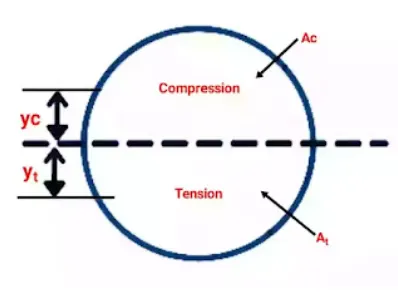
on the neutral axis, the area under compression is equal to the area under tension,
Ac = Aₜ = πd²/8
yc = yₜ = 2d/3π
|
Zₚ = (πd²/8 × 2d/3π) + (πd²/8 × 2d/3π)
Zₚ = d³/6
|
| 4. |
Cicular Hollow section |
Zₚ = (D³ - d³)/6
|
DESIGN STUDY FOR SECTION MODULUS
The cross section of the design was taken and the Section Inertia Analysis was run.
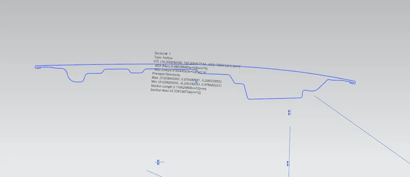
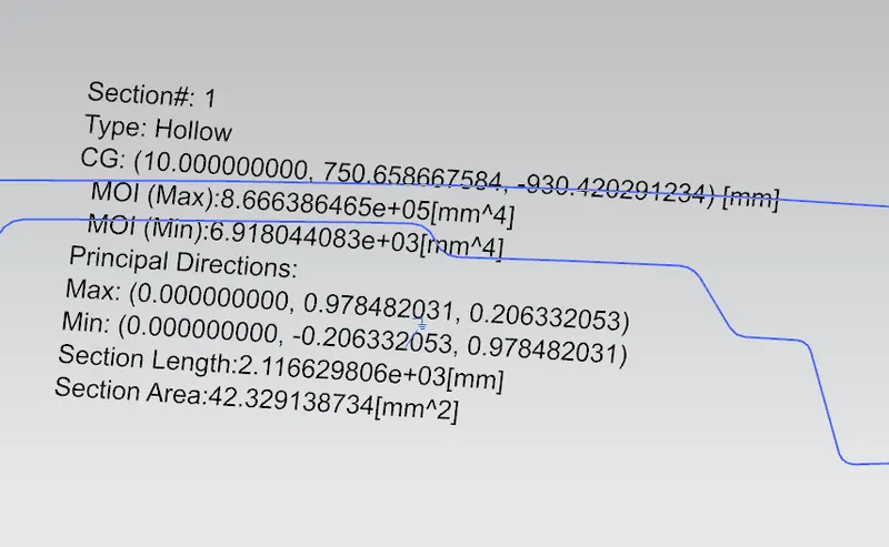
Moment of Inertia (max)= 8.66638 x 10⁵ x mm4
Moment of Inertia (min)= 6.91804 x 10³ x mm4
Y = 482.8096mm = 482.8096/2 = 241.4048 mm
S = I/ Y
= 6.91804 x 10³ / 241.40
= 28.657 mm3
HOOD DESIGN OPTIMIZATION
By offsetting the inner panel of the hood downwards by 0.2 mm, we get
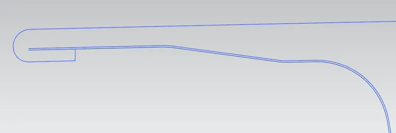
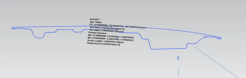
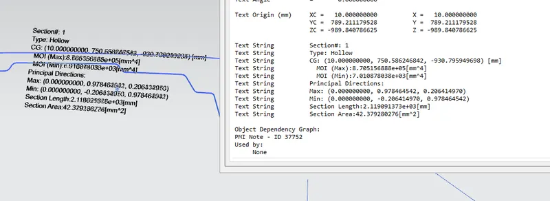
Moment of Inertia (max)= 8.70515 x 10⁵ x mm4
Moment of Inertia (min)= 7.01087 x 10³ x mm4
Y = 482.8096mm = 482.8096/2 = 241.4048 mm
S = I/ Y
= 7.01087 x 10³ / 241.40
= 29.042 mm3
CONCLUSION
RESULT- A difference between the two section modulus can be seen. It is clear that on increasing the depth of the design and thus by increasing its cross section, the section modulus of the region also increased.
Thus by increasing the cross section area, we can achieve a higher value of section modulus and therefore overall resistance (or the strength) of a body can be increased. Hence a conclusion can be made as to which design would be better as per the requirements.