Section Modulus calculation and optimization
AIM
To find the section modulus of the hood and optimization to improve the overall section modulus.
SECTION MODULUS
Section Modulus is also referred to as the Polar Modulus or the Torsional Sectional Modulus. It is denoted by Zp.Section Modulus is the geometric property of the given cross-section of any shaft or beam structures. It is the direct measure of the strength of the shaft section or the beam section. Higher the section modulus of a structure, the more the resistive it becomes to bending.
The second moment of area is also known as the moment of inertia of a shape. It is directly related to the area of material in the cross-section and the displacement of that area from the centroid. Once the centroid is located, the more important structural properties of the shape can be calculated. The axis that determines the centroid is also known as the neutral axis (N/A).
The second moment of area is a measure of the 'efficiency' of a shape to resist bending caused by loading. A beam tends to change its shape when loaded. The second moment of area is a measure of a shape's resistance to change.
Formula of section Modulus
It may be defined as the ratio of total moment resisted by the section to the stress in the extreme fibre which is equal to yield stress.
Which is equal to yield stress.
Therefore
S=I/y, Where
S= Section modulus (mm^3)
I = Moment of inertia of the section to the stress in the extreme end of the object (mm^4)
Y= Distance between the neutral axis and extreme end of the object (mm).
Area Moment of Inertia
The area moment of inertia of a beam cross section area measures the beam ability to resist bending. The larger the moment of inertia less will be the bend.
Where,
M = Bending Moment
I = Area moment of Inertia
E = Young modulus
R = Radius of gyration
Neutral Axis
When beam is subjected to pure bending the top most fibres of the beam are subjected to maximum compression, while the bottom most fibre of the beams are subjected to maximum tension.
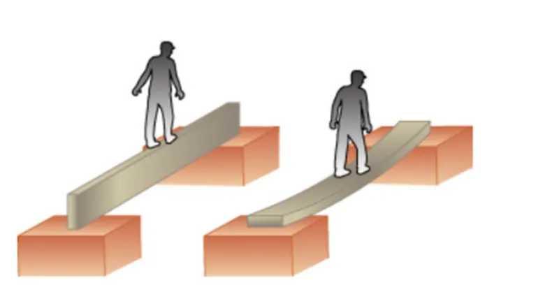
This picture contains the following scene, Diagram of a beam on its narrow edge supported at both ends. A man is walking on a straight beam. Diagram of a beam resting on its flat side supported at both ends. A man is walking on the straight beam and its bending in the middle.
SECTION MODULUS CALCULATION AT SECTION OF THE HOOD
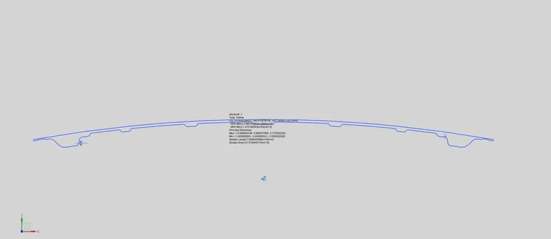
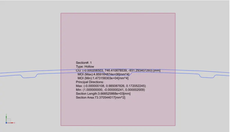
MOI (Max)= 4.859164874e+06[mm^4]
MOI (Min)= 1.473158303e+04[mm^4]Y
As per the section modulus equation,
S=I/Y
I= MOI (min) value is considered
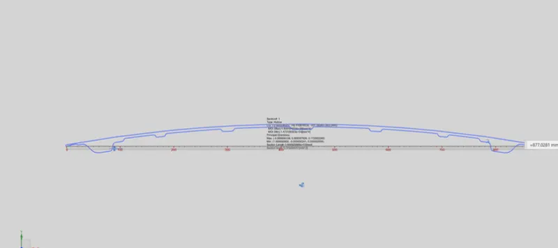
Y= Total distance/2 , total distance
= 877.02mm/2
Y= 438.51mm
Therefore, S= 14731.583^4/438.51mm
S= 33.594mm^3
DESIGN OPTIMIZATION BY INCREASING THE DEPTH OF THE INNER PANEL BY 0.5MM
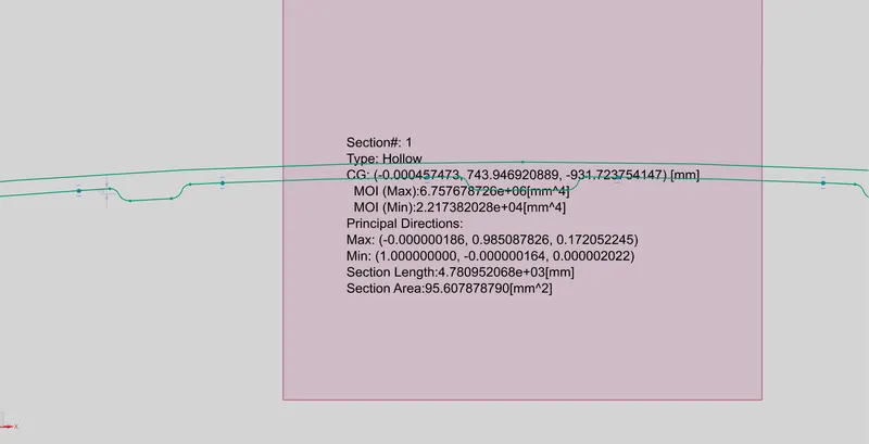

MOI (Max)= 6.757678726e+06[mm^4]
MOI (Min)= 2.217382028e+04[mm^4]Y
As per the section modulus equation,
S=I/Y
I= MOI(min) value is considered
Y= Total distance/2 , Total distance
= 877.02mm/2
Y= 438.51mm
Therefore, S= 22173.8203mm^4/438.51mm
S= 50.566mm^3
Final result
Thus the stiffness of the car hood has been increased by increasing its area moment of inertia.
CONCLUSION
Section modulus is directly dependent on the area moment of inertia and the distance from the neutral axis. Hence, to improve the geometry of the carry more bending load, the section modulus can be improved by increasing the area MOI of a given section.
We can increase the section modulus just increasing the gap between the outer & inner panel.