Roof Design
ROOF DESIGN:-
Objective:-
In this project, i have done the automobile car roof from the given input skin data and also followed a Mastersection of the Roof rails and BOWs.
Software used:-
SIEMENS NX CAD
Roof :-
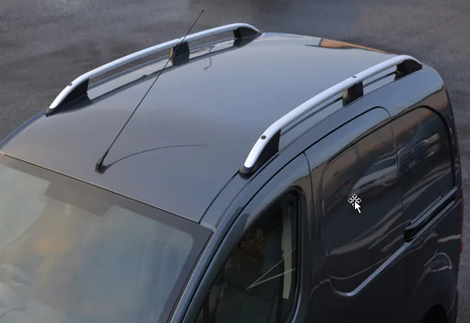
Roof is a component to encloses a passenger cavity and this roof protects the car and the passengers who sits inside the sun, rain,and also from the various conditions.and the support rails inside the roof helps to protects the passender from the accident.
The required tool opening angle is minimum 3 Degrees
1.Factors which is considered before creating Ditch area,
2.Headroom clearance
3.Visibility criteria
4.Back door assembly
5.Windshield assembly
Given Input :-
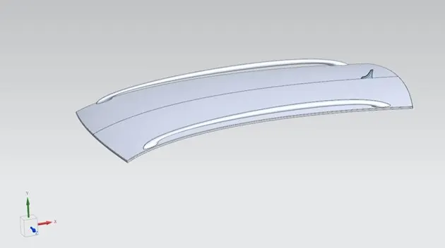
The Automobile roof have some support roof panels inside they are , I have to create the following supports following the master section.
- Front roof rail
- Rear roof rail
- Center roof rail
- Bow roof 1
- Bow roof 2
- Ditch area
Roof:-
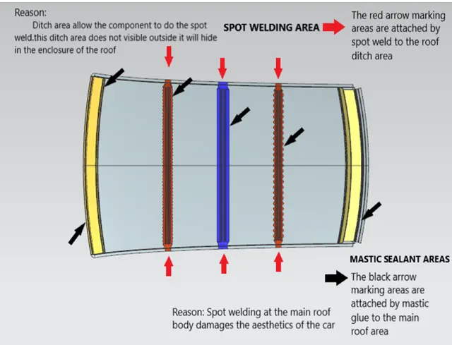
The roof is made from a sheet of at least 0.65mm. This protects the cabin from external conditions and objects. The ditch areas are spot welded to the pillars of the car and certain areas of the roof rails, welding on the upper surface is avoided in order to maintain a good aesthetic.
Front Roof rail:-
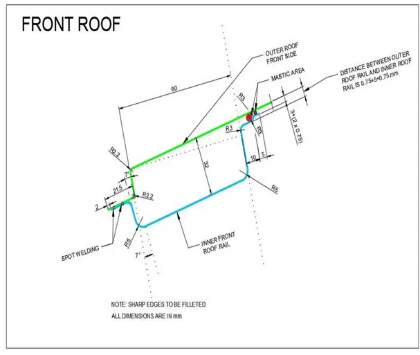
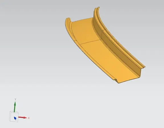
The front roof rail is made from a sheet of at least 1mm thickness. This part acts as a support for the roof sheet on the front it also provides a mounting area for the windshield. It is designed with support requirements, visibility criteria and headroom space in mind. The roof is fixed to the roof rails with the use of mastics while the ends are spot welded.
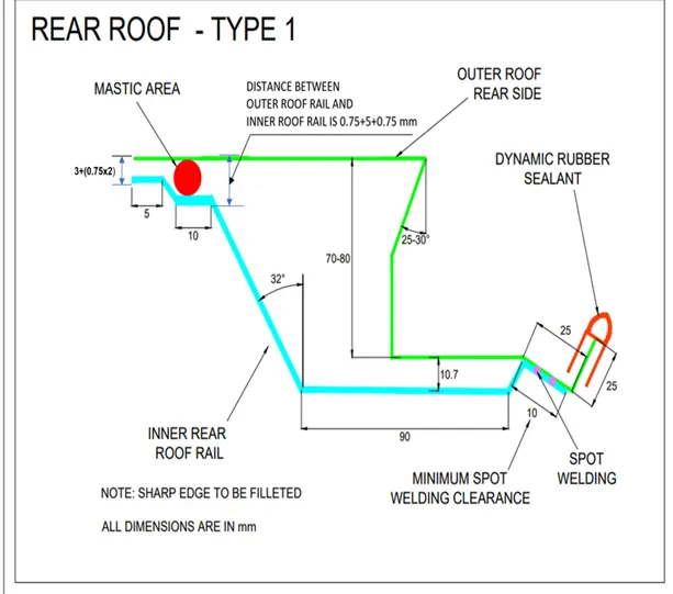
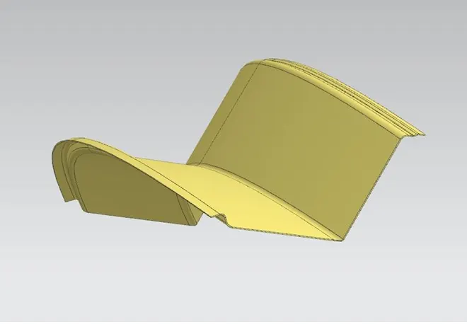
Rear Roof rail:-
The rear roof rail is made of a sheet of at least 1.2mm thickness. The rear roof rail acts as a support for the rear end of the roof and also supports the rear window in some cases also supports the rear door. It\'s designed in accordance with the support requirements of roof, window and rear door, and also rear visibility and headroom criteria. The roof is fixed to the roof rails with the use of mastics while the ends are spot welded.
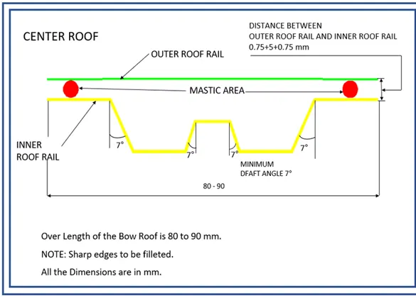
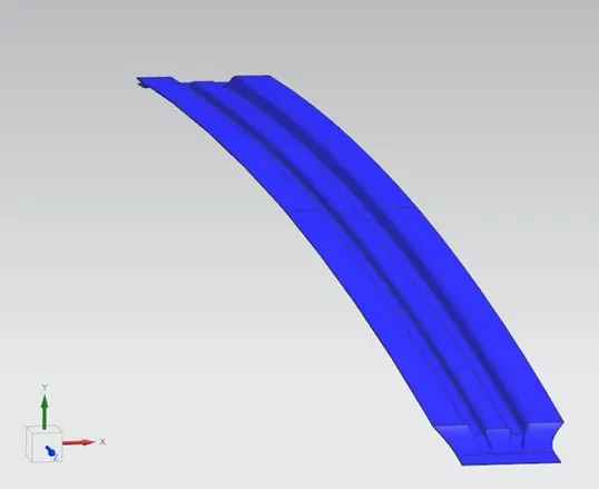
Center Roof rails:-
This is the roof rail that runs between the B pillar of the car and provides support to the centre of the roof sheet they are usually 1-2mm thick and also provide a support area for the centre cabin light mount. The roof is fixed to the roof rails with the use of mastics while the ends are spot welded.
Bow Roof rails:-
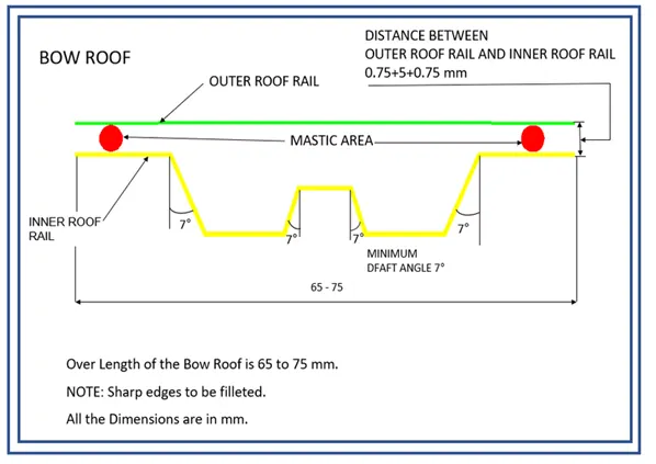
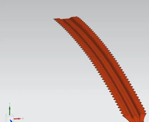
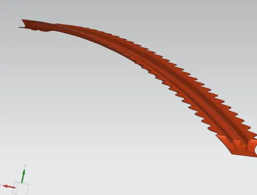
The bow roof rails provide additional support to the roof and are at least 1mm thick, they are positioned in such a way that they provide maximum support to the roof, Care must be taken so that they do not intrude into the headroom requirements of the car. Bow roof rails are an optional feature provided as required by the design. Small cars may have none while large ones may have 3 or more, they may also be integrated into the centre roof rail in some cases. The roof is fixed to the roof rails with the use of mastics while the ends are spot welded.
Ditch area:-
Ditch area is a extended portion of the main roof concelled by other BIW pannels.The rails support of the roof are attached to the ditch area using spot weld.
MASTERSECTION:-
FRONT ROOF RAIL
REAR ROOF RAIL
CENTER RAIL ROOF
BOW ROOF 1
COMPLETE ROOF:-
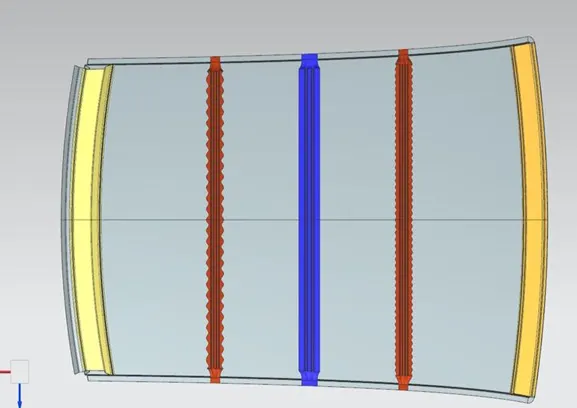
IN THIS ROOF DESIGN I HAVE DONE THE TWO ANALYSIS:
1. HEAT DISTORTION ANALYSIS.
2. SNOW LOAD CONDITION ANALYSIS.
HEAT DISTORTION ANALYSIS.
Heat distortion temperature is a temperature at which the metal softens and deform under a specific load.This study is done to check the ability of the roof to withstand high temperature with respect to the position of the reinforcement which contribute to the increase strength.
Bow–Roof Prediction Formula
W = [1.73 x 10^(-3) x L] + [1.85 x 10^(-8) x (R^2)/t] + [ 1.10x10^(-3) x l] - 2.68
Where,
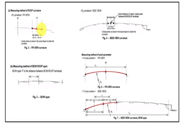
L = Roof Length in X-Direction[mm](Roof dimension in 0-Y)
R = Roof curvature
R = 2(Rx*Ry)/(Rx+Ry)
Rx = X curvature
Ry = Y curvature
t = Roof plate thickness [mm]
l = Bow Roof Span [mm]
Judgment Condition
"OK< 2>
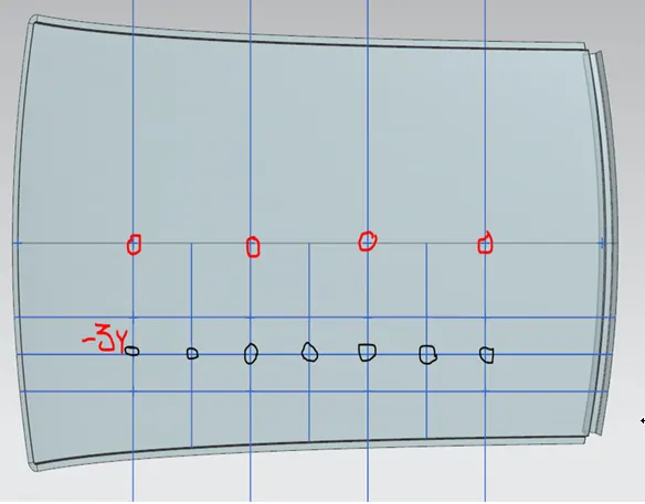
By using this we need to calculate the value for the respective parameters
CALCULATION TABLE FOR HEAT DISTORTION:-
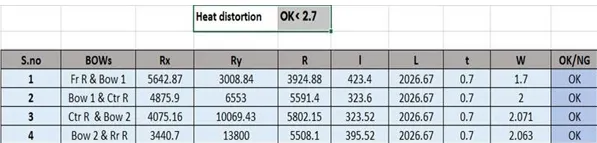
Heat distortion passes the Judgement conditions.
SNOW LOAD CONDITION:-
Snowload condition mostly carried out in the European Countries. In India the winter season there is no snow compared to European countries.
pump talk petro canada:driving blind can get you fined clean the
Snow Load Prediction Formula
Qr = [Iy x t2] / [α x s x [(Rx + Ry)/2]2 x 10-8]
Note: The Qr value given over here is correct. There was a typo error in the formula given in the video.
Where,
α = My x Lx2 x 10-12 , My = Y(Ly-Y)
t = Roof plate thickness [mm]
Ly = Distance between the front and rear roof Rails on the Vehicle along with 0Y[mm]
Length of Roof panel with the center point between Roof rail Front /Rear as the front and rear reference point.
Lx = Distance between the Left and Right end of the roof on the Roof BOW [mm]
The width of the roof panel is exposed on the surface.
Y = Distance front Front Roof Rail to Roof BOW[mm]
s = Distance for which Roof BOW bears divided load [mm]
s = L1/2 + L2/2
Iy = Geometrical moment of inertia of Roof BOW (Y cross-section )[mm4]
Rx = Lateral direction curvature radius of roof panel Y cross-section on Roof BOW [mm]
Roof panel curvature Radius of the Length Lx in Front view
Ry = Longitudinal Direction curvature radius of the Roof panel X cross-section on Roof BOW [mm]
Roof panel X curvature radius of length s in Side view
Judgment condition
Qr ≥ 3.1
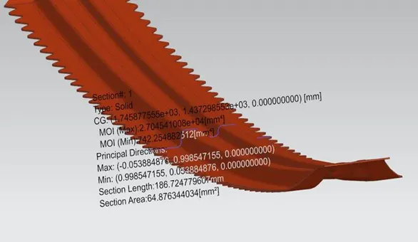
Section modulus calculated for the snowload condition :- (Min value considered)
BOW ROOF 1:-
BOW ROOF 2:-
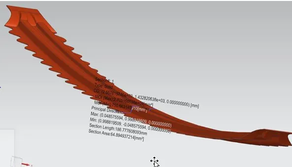
CENTER ROOF RAIL:-
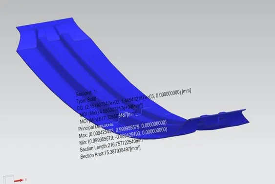
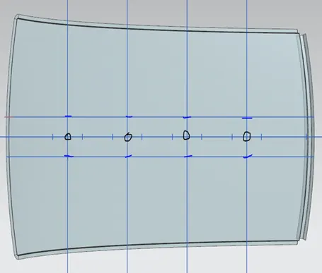

Snowload condition also passed the judgement condition.
JOINING CONDITIONS:-
DRAFT ANALYSIS OF THE ROOF AND ITS COMPONENTS:- (Minimum Draft Angle for the Sheet metal components are 7degree)
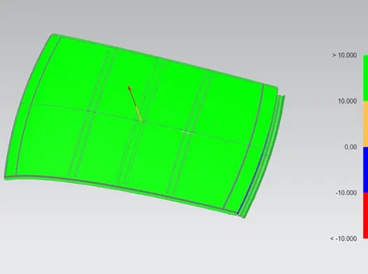
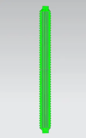
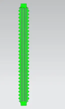
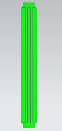
Draft analysis clears the components.
CONCLUSION:-
Thus the roof of the car is designed as per the given skin data and necessary reinforcements are given. The roof is also analysed as per the heat distortion and snow load conditions and is found to be within limits. Draft analysis is also carried on all the components and there are no issues in this regard. Therefore the roof design may be sent to the next step of the design process.