Roof Design
OBJECTIVE -
- The objective of this project is to design car roof with essential flanges and reinforcements like ditch area , front roof rail , bow roofs, central roof rail and rear roof rail for the the given styling surface.
- Perform a curvature study on the roof and perform the calculations for the heat distortion and snow load criteria to determine whether the bow roofs are at the correct positions.
- Finding moment of inertia and section modulus for Bow roofs , central roof rail , front roof rail and rear roof rail .
- Perform the draft analysis for each reinforcements.
INTRODUCTION -
An automobile roof or car top is the portion of an automobile that sits above the passenger compartment, protecting the vehicle occupants from sun, wind, rain, and other external elements.
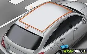
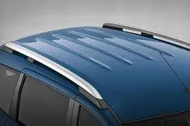
When it is seeing from outside of the car, it is just closing the top portion. But in design point of view, it is hard to create the design. Because of you have to create no of support rails for enough strength to withstand the load. Bow roofs are primarily fixed in flatter region to enhance strength.
Front roof and rear roof rails are fixed to the ditch area using spot weld operation. But front, rear bow roof and center roof rails are fixed to roof using mastic sealants. We don’t want so much gap between roof rails and bow roof area. So, we reducing the NVH issues.
DESIGN CONSIDERATION OF ROOF:
- Visibility criteria
- Head room clearance
- Bow roof position
- Heat distortion and Snow load criteria
- Draft analysis
ROOF CRUSH TEST:
OVERVIEW OF THE TEST:
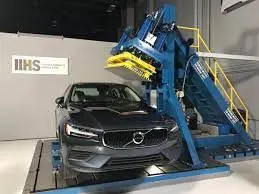
Roof strength evaluations consist of a quasi-static test conducted on a vehicle’s roof in a manner similar to tests used to judge compliance with Federal Motor Vehicle Safety Standard 216 (Office of the Federal Register, 2009). The main differences between the procedure specified by the Insurance Institute for Highway Safety (IIHS) and that specified by the U.S. federal government are that the IIHS procedure are,
- Specifies testing one side of a vehicle’s roof
- Does not include a headroom criterion
- Specifies testing to a given displacement instead of a given force level
- Specifies setting the vehicle’s pitch angle during testing based on the measured on-road pitch angle.
An overall rating is assigned based on the peak strength-to-weight ratio (SWR) measured within 127 mm of plate displacement.
TESTING OF ROOF -
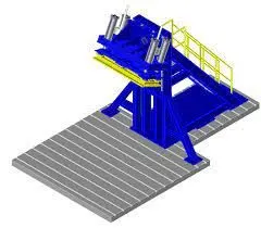
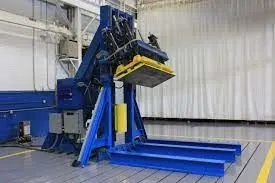
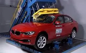
Roof strength evaluations are conducted on a quasi-static test system manufactured by MGA Research Corporation.
The system consists of an upright assembly and an attached loading head that can be fixed at varying heights from the ground as well as at pitch angles ranging from −5 to +5 degrees to accommodate testing on the driver or passenger side.
The roll angle is permanently fixed at 25 degrees. Four hydraulic actuators control the movement of the platen along two linear guides. The entire system is mounted on a T-slot bed plate anchored to the floor of the test facility.
GOAL OF ROOF CRUSH TEST :
To minimize the protrusion into the occupant compartment , so that the seat belts and air bags can do there job in protecting the occupant
CONDITIONS TO FOLLOW FOR ROOF CRUSH TEST :
There are two conditions that should be followed for the roof crush test , they are
INITIAL CONDITION :
- Close and lock all the doors
- Close all the windows
SECOND CONDITION :
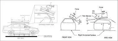
Fix the body sill or chassis frame on a hard lever surface horizontally
METHOD OF APPLYING THE FORCE :
The load is applied in such a way that 50 is tilted from the front end to the rear end and the load will be in 1800 mm in length and 750 mm in width . The load is applied at the position of 250 from the flatness of the roof . The load is applied on the roof for almost 120 sec and the crush speed at which the load applied is 13 mm/sec or less than that.
CALCULATING THE STRENGTH-TO-WEIGHT RATIO (SWR) RATING:
Force and displacement data are recorded for 5 seconds prior to each test, while the test system holds the loading platen at initial roof contact.
The data recorded from 1 to 4 seconds of this hold time are averaged for each channel to produce a measurement offset that is subtracted from the data recorded during the crushing of the roof.
After removing the offset for each channel, the force-displacement curve is plotted using the summed output from the five load cells and the average displacement from the four LVDTs. The maximum force prior to 127 mm of platen displacement is divided by the measured curb weight to obtain the SWR.
Both the force and curb weight are rounded to the nearest pound prior to performing the calculation, and the resulting SWR is rounded to the nearest one-hundredth of a unit.
Displacement is rounded to the nearest 0.1 mm. (The maximum displacement where the load can be used for the vehicle rating is 126.9 mm.) The vehicle’s rating is assigned based on the boundaries listed in.
RESULTS :
If the displacements goes above the requirements level then we have to increase the bow roof thickness or add more mastics points to increase the strength . the stronger the roof the better it can protect the occupants in the roll over crashes.
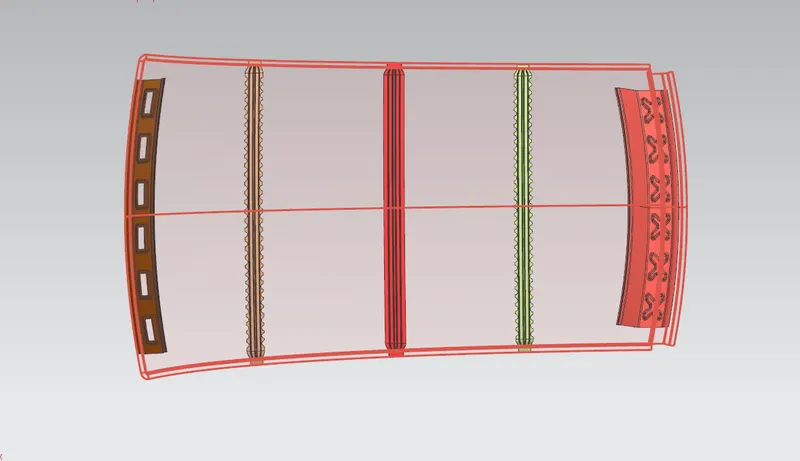
Different Components Of A Car Roof -
- Front roof rail
- Bow roof rails
- Central roof rail, and
- Rear roof rail
FRONT ROOF RAIL:
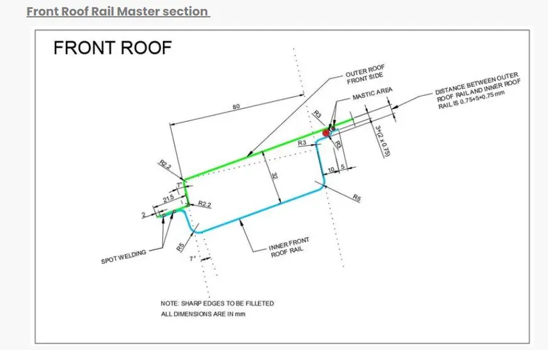
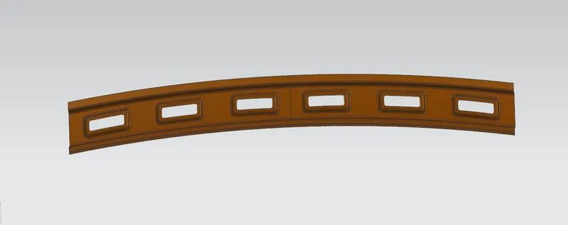
Front roof rail is used for supporting the roof for externally applied forces occurring at accidents. When we increasing the front roof rail is good for strength but also it is not for drivers because of it hide visibility of road.
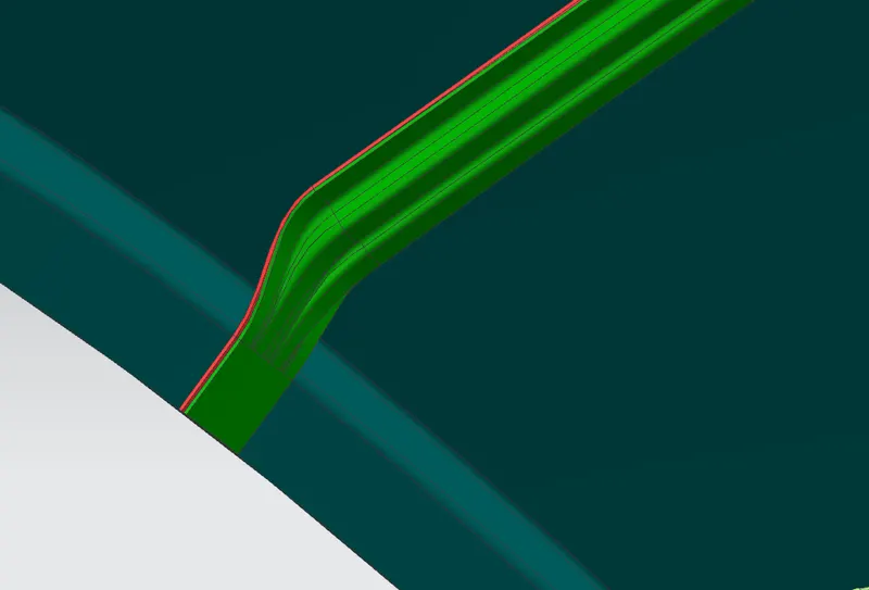
When considering the parameters of roof rail, give them 60-80mm length, proper draft angle and also using the embosses for increasing the strength. Front section of front roof rails spot welded to the front ditch area and other end is fixed with help of mastic sealants.
REAR ROOF RAIL:
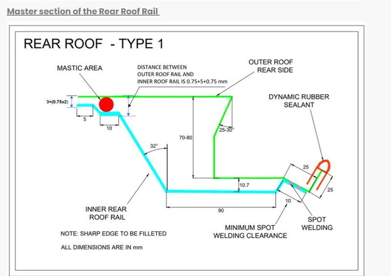
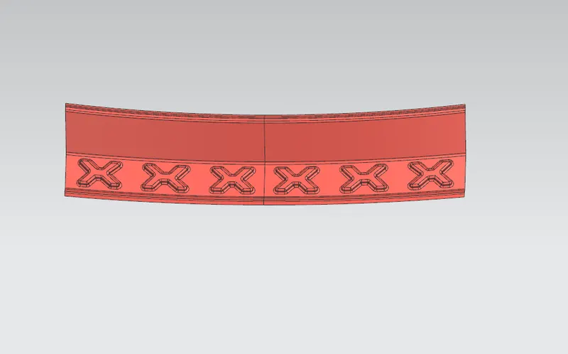
Rear roof rail is creating to length 80-100mm with proper draft angle. Give embosses on the sheet to ensure the enough strength for holding the roof structure. When considering the all parameters like length, width, sealants, rubber materials, wind shield to create the design properly.
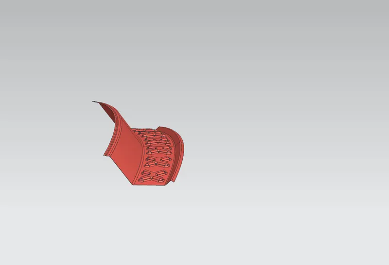
BOW ROOF RAIL -
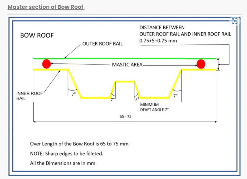
BOW ROOF FRONT:
The bow roofs are given to the improve the torsional stiffness and load bearing capacity of the roof structure. When number of bow roofs are given by the roof dimension. Longer the roof area we have to give the more bow roof to the structure.
Positioning of the bow roofs are decided by the curvature study. The Heat distortion and Snow load criteria are checked to analyze the bow roof position by various condition.
We also give the Mastic area for fixing the Bow roof to the roof outer. Each mastic sealants are having 80mm circular effective area of surroundings. Thickness of the Bow roof is 0.75mm.
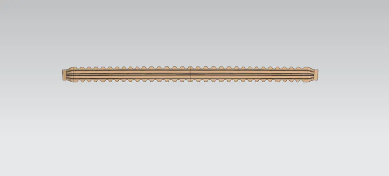
BOW ROOF REAR:
It is also same to the Front bow roof but the positioning bow roof only change. The bow roofs are given to the improve the torsional stiffness and load bearing capacity of the roof structure. When number of bow roofs are given by the roof dimension. Longer the roof area we have to give the more bow roof to the structure.
But, remember we place bow roof in flatter region for enhance strength of the roof.
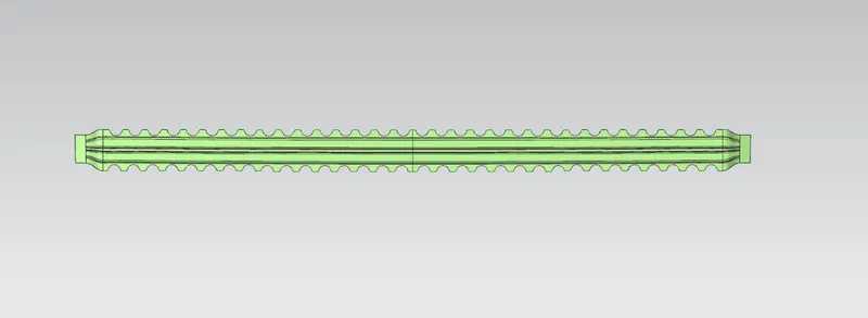
CENTER REINFORCEMENT ROOF RAIL -
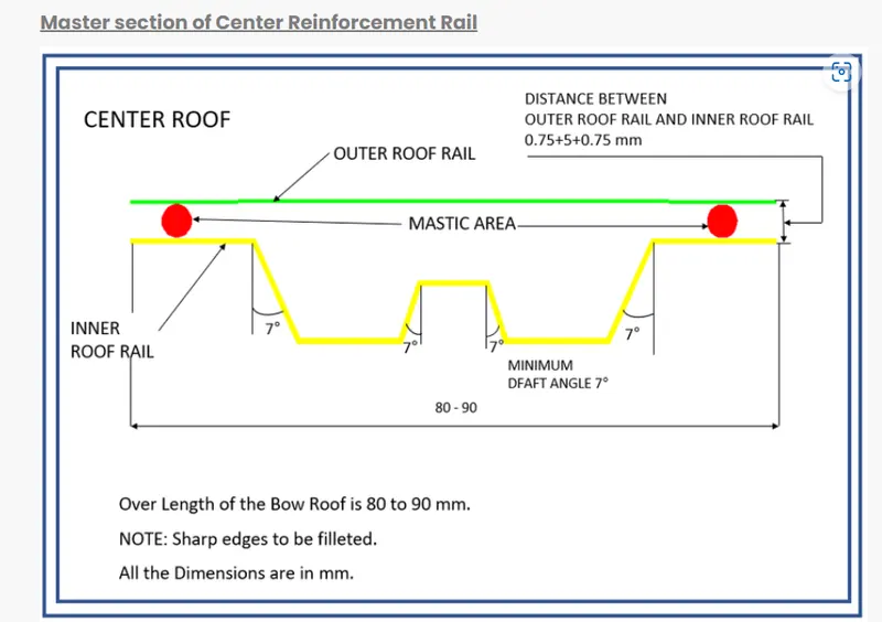
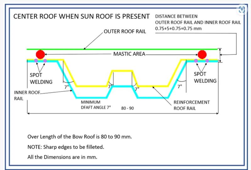
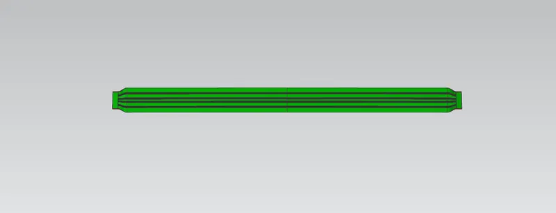
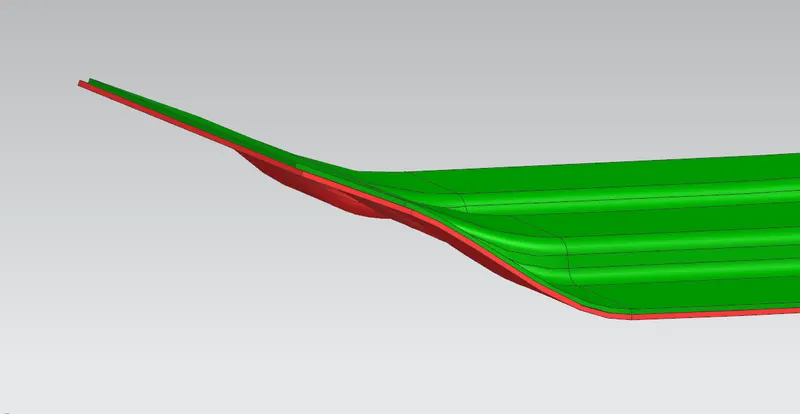
Reinforcement Center roof rail is effective support to the flat area structure roof. Because of center area of roof is more susceptible to failure under action of load. Usually, Reinforcement center roof rails are fixed at the center of the roof for connecting to the B – Pillar support structure, it will used for roll-over test.
Center bow roof and reinforcements are placed at the center of the roof structure. They two are connecting to help of spot - welding operation. Thickness of the Reinforcement center roof rail is 0.75mm.
CURVATURE STUDY ON THE ROOF:
- Heat Distortion
- Snow Load
HEAT DISTORTION:
The heat distortion study the plays an important role in sheet metal application. Heat distortion is temperature limit above which material cannot be used for structural application. This study is useful to find where the material starts to soften when exposed to a fixed load at elevated temperature. In order to avoid the bending, damage, to the roof based on the heat distortion temperature, this study will provide that at which position, the bow roof gives enough strengthen to the roof.
Bow Roof Prediction Formula:
HEAT DISTORTION CRITERIA:
W = [1.73 x 10^(-3) x L] + [1.85 x 10^(-8) x (R^2)/t] + [ 1.10x10^(-3) x l] - 2.68
Judgement Condition: OK<2.7
Where,
L= Roof Length in X- direction [mm](Roof Dimension in 0-Y)
R = Roof curvature
R = 2(RX*RY)/(RX+RY)
RX = X Curvature
RY = Y Curvature
t = Roof plate thickness [mm]
I = Bow roof span [mm]
Thickness for the Roof(t):
Roof Outer Panel, t= 0.75mm
Front Roof Rail, t = 0.75mm
Rear Roof Rail, t = 0.75mm
Bow Roof Rail Front, t = 0.75mm
Bow Roof Rail Rear, t = 0.75mm
Reinforcement centre roof rail, t = 0.75mm
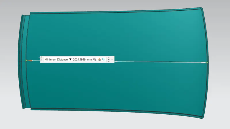
ROOF LENGTH (L):
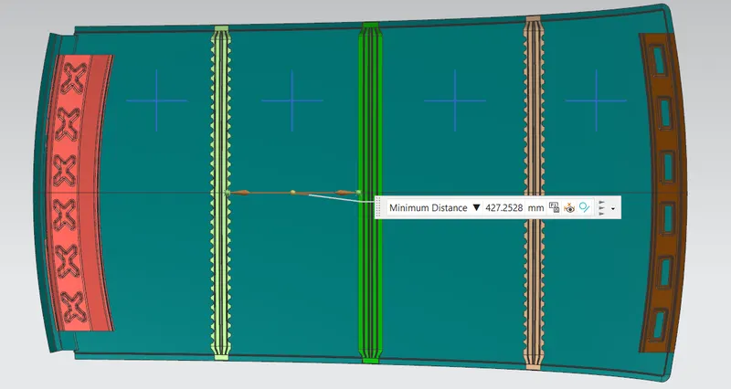
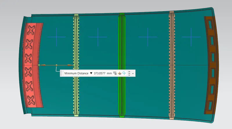
BOW ROOF SPAN (I):
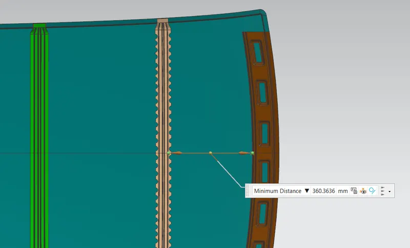
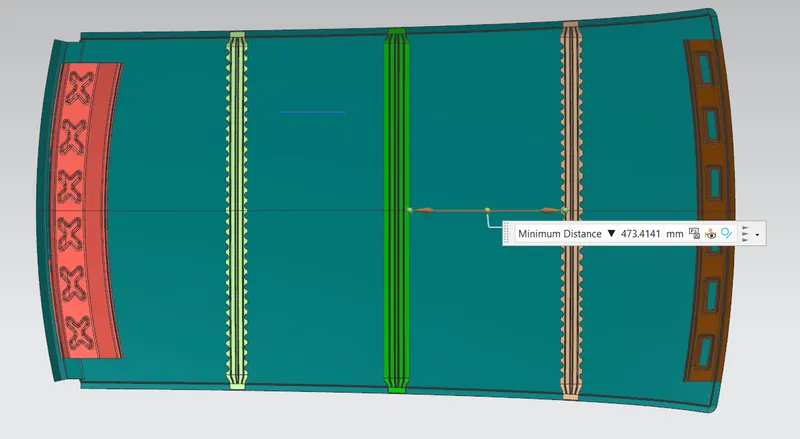
Here we want to take the distance from front roof rail to bow roof front for finding the bow roof span(I). We will measure another bow roof spans also.
RX & RY (X & Y Curvature):
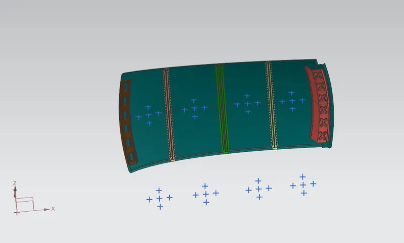
- From 0-Y axis, offset 0-Y line at a distance of 300mm, which will be the 3-Y line. After that, at 100mm, lines are offset to either side of 3-Y line. Now center lines are drawn through the midpoints of the line between each adjacent roof rail edges respectively. Now offset this centre line to 100mm in both directions. Intersection points are marked on the sketch.
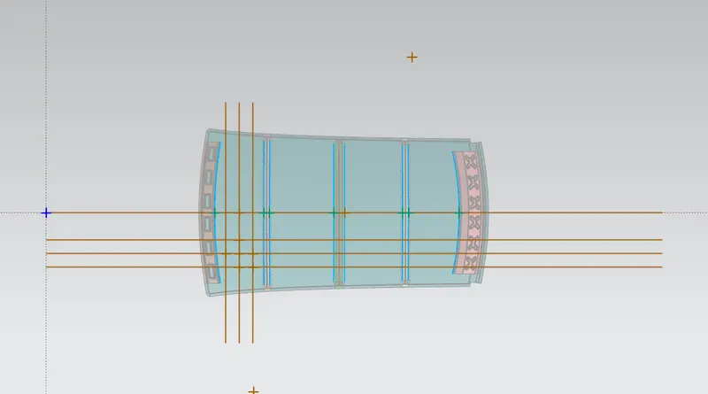
- Now repeat the same process further.
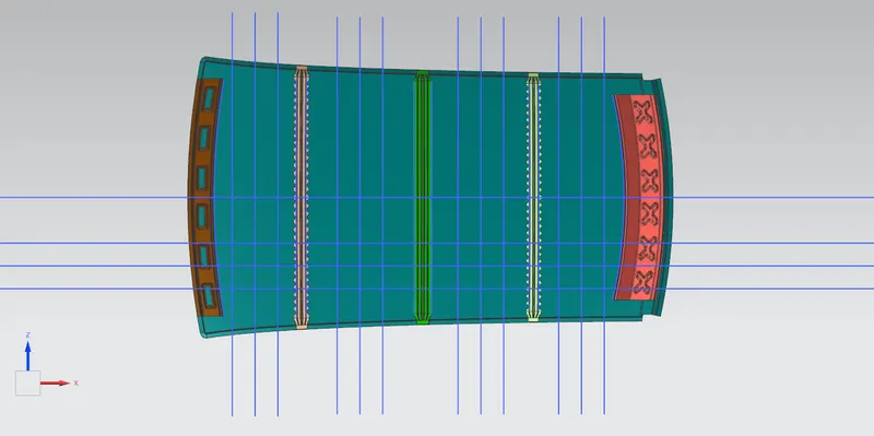
- Make all geometry lines as construction lines, except points.
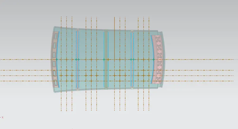
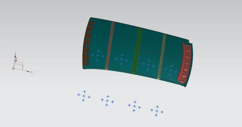
- Project the intersection points on sketch to the roof surface.
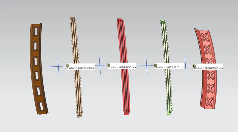
- Join the intersection points in roof surface using the arc curve and measure the radius using the local radius analysis command.
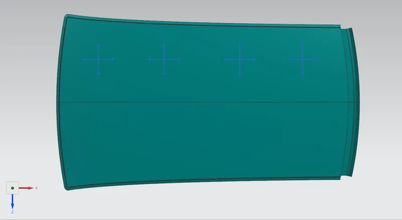
RX Value:
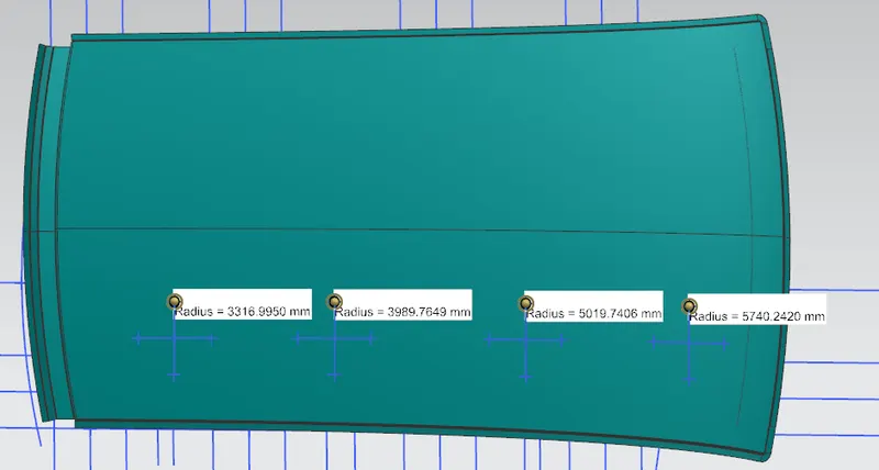
RY Value:
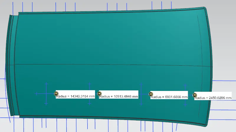
We have the necessary values for finding the heat distortion value(W):
W = [1.73 x 10^(-3) x L] + [1.85 x 10^(-8) x (R^2)/t] + [ 1.10x10^(-3) x l] - 2.68
Apply the all the values,

From the above table, it can be concluded that all values of W<2.7 and also not W>3.1 so thus infers that current positioning of bow roof rails are good as per design.
SNOW LOAD CRITERIA :
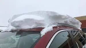
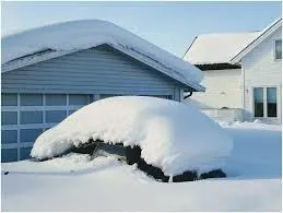
Snow load criteria study is used to check the durability of the roof to withstand the snow fall on the roof and reflex it is original shape without any permanent deformation after load being removed. The roof should be designed in such a way that when the snow is removed, the roof should go in it's its original position.
SNOW LOAD CRITERIA:
Qr = [Iy x t2] / [α x s x [(Rx + Ry)/2]2 x 10-8]
Where,
α = My x LX2 x10-12, My = Y(Ly–Y)
Judgement condition = Qr > 3.1
250 < s < 380
t = Roof plate thickness[mm]
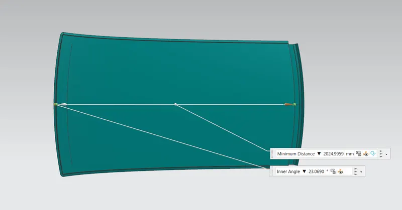
LY = Distance between the front and rear roof rails on the vehicle along with 0Y[MM],
Length of roof panel with the center point between roof rails front/ rear as the front and rear reference point.
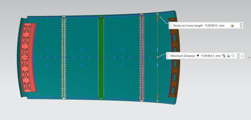
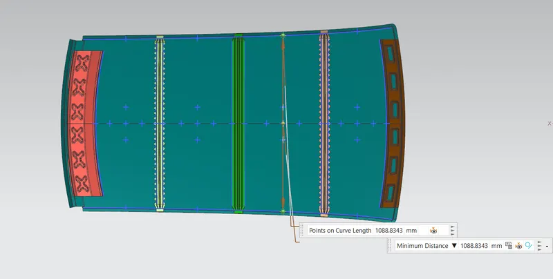
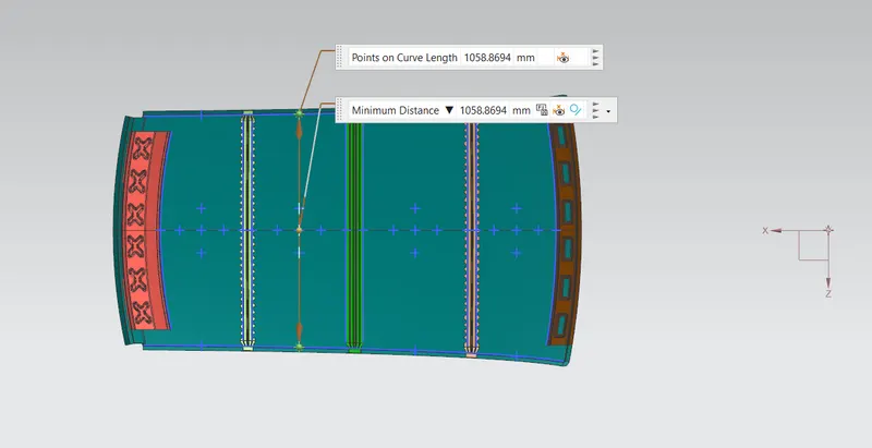
LX= Distance between the left and right end of the roof on the roof bow[mm],
With of the roof panel exposed on the surface.
Y = Distance between Front roof rails to roof bow [mm],
s = Distance for which roof bow bears divided load [mm],
s = L1/2 + L2/2
Iy = Geometrical moment of inertia of roof bow (Y cross – section) [mm4],
RX = Lateral direction curvature radius of roof panel Y cross section on roof bow [mm4],
Roof panel curvature radius of the length LX in front view.
RY = Longitudinal direction curvature radius of the roof panel X cross section on roof bow[mm4],
Roof panel X curvature radius of length s in side view.
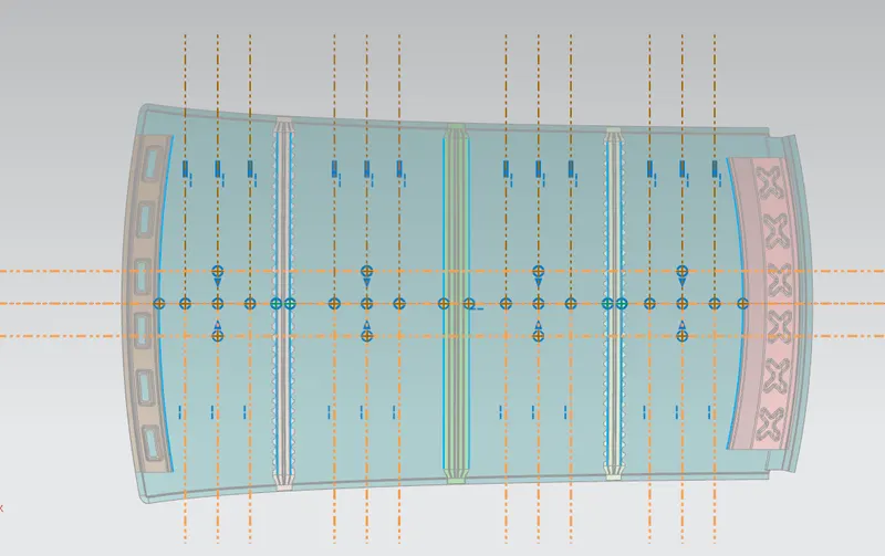
RX & RY (X & Y Curvature):
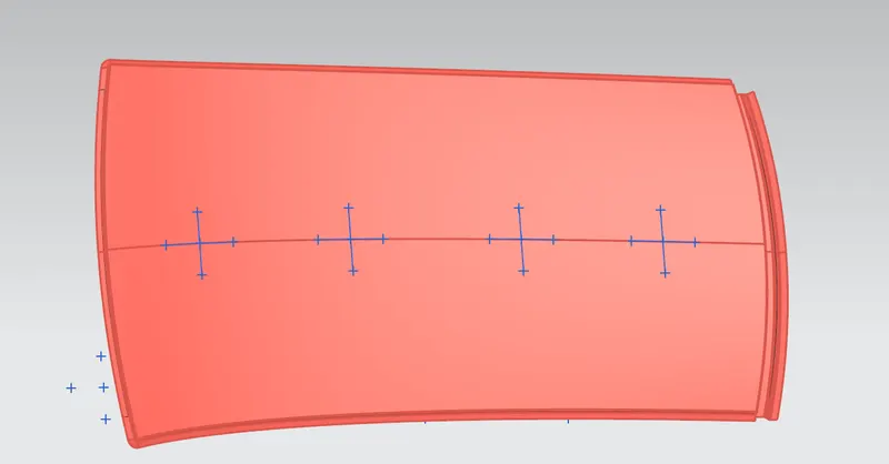
- At 0-Y axis on perpendicular plane to roof. Draw 100mm lines offset to either side of the of 0Y axis line. Now center lines are drawn between each adjacent roof rail respective. Intersection points are marked on the sketch. Make all the geometry in construction lines except points.
- Project the intersection points in the sketch are projected to roof surface.
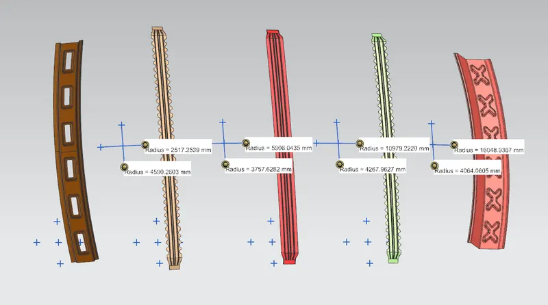
- Join the project points using arc curve and measure the radius value using minimum radius comment.
RY Value:
RX Value and RY Value:
LY Value:
LX1Value:
LX2Value:
LX3Value:
MOMENT OF INERTIA:
BOW ROOF FRONT:
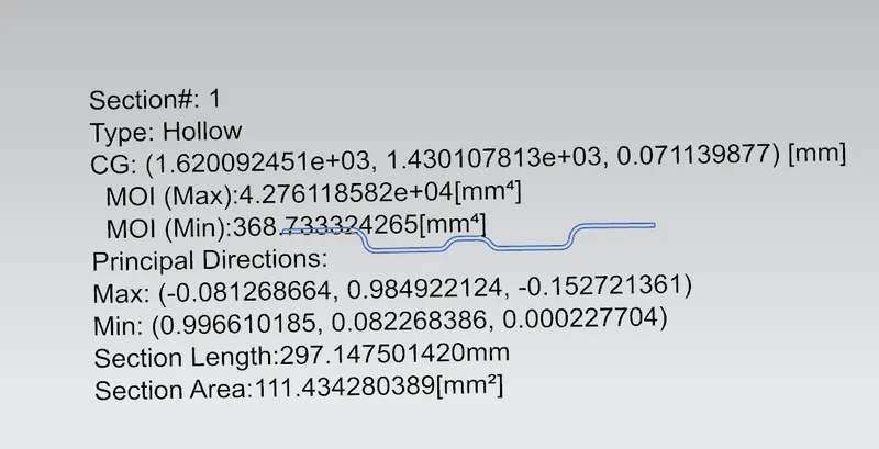
We take the minimum moment of inertia value is IY1 = 368.7333 mm4.
BOW ROOF REAR:
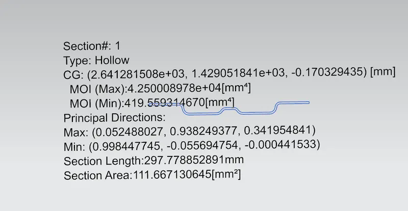
We take the Minimum moment of inertia value is IY2 = 419.5593 mm4.
CENTER REINFORCEMENT RAIL:
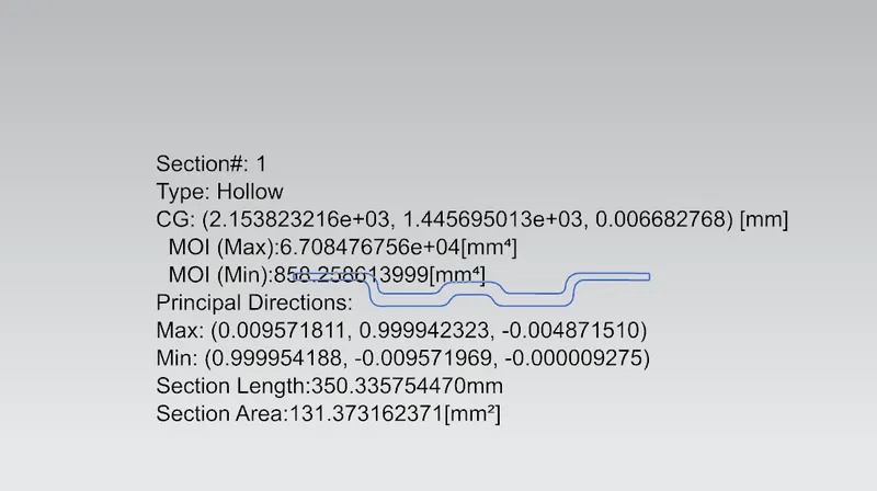
We are taking the Hollow type for finding moment of inertia of the part. Therefore, reason is other two bow roofs are having solid structure. But center reinforcement roofs having the two solid part. So, that why we are joining to them and check for moment of inertia.
Minimum moment of inertia for center reinforcement rail is IY3 = 858.2586 mm4.
FINAL RESULTS OF SNOW LOAD CRITERIA:
We have the necessary values for finding the Snow load value(W):

For the roof structure to pass the snow load condition, it must have Qr values from above 3.1.
Qr > 3.1
So, we did the curvature study on the roof. The outcome shows that the roof is good according to both the criterias, i.e, Heat Distortion Criteria and Snow Load Criteria. So, position of the bow roofs and center reinforcement roofs is right.
SECTION MODULUS:
The moment carrying capacity of an object is directly dependent on geometrical property (I) and material property (E) of an object, which is collectively termed as flexural rigidity (EI). Geometry of an object plays an important role in load bearing capacity of an object which is indicated by moment of inertia of a section.
Therefore, section modulus is the predominant factor which evidences the strength of an object and is defined as the ratio of the moment of inertia of the object about its centroidal axis to the distance of the extreme fibers of the object from the neutral axis.
There are two types of section modulus we have,
- Elastic section modulus
- Plastic section modulus
Elastic modulus is defined as,
S = I/Y
S – Section modulus,
I – Second moment of area
Y – distance from the neutral axis to outer most fiber of the object.
BOW ROOF FRONT:
Moment of inertia (Max), Imax = 4.276 x 104 mm4
Moment of inertia (Min), Imin = 3.687 x 102 mm4
Section modulus = moment of inertia / distance between the neutral axis to extreme end of the object.
S = I/Y
Y = 33.94 mm
For maximum MOI,
S = 4.276 x 10⁴ / 33.94
SMAX = 1259.87 mm3
For minimum MOI,
S = 3.687 x 10² / 33.94
SMIN = 9.64 mm3
BOW ROOF REAR:
Moment of inertia (Max), Imax = 4.25 x 104 mm4
Moment of inertia (Min), Imin = 4.19 x 102 mm
S = I/Y
Y = 32.25 mm
For maximum MOI,
S = 4.25 x 10⁴ / 32.25
SMAX = 1317.82 mm3
For minimum MOI,
S = 4.19 x 10² / 32.25
SMIN = 12.99 mm3
CENTER ROOF RAIL:
Moment of inertia (Max), Imax = 6.7 x 104 mm4
Moment of inertia (Min), Imin = 8.58 x 102 mm4
Section modulus = moment of inertia / distance between the neutral axis to extreme end of the object.
S = I/Y
Y = 38.96 mm
For maximum MOI,
S = 6.7 x 10⁴ / 38.96
SMAX =1719.71 mm3
For minimum MOI,
S = 8.58 x 10² / 38.96
SMIN = 22.02 mm
FRONT ROOF RAIL:
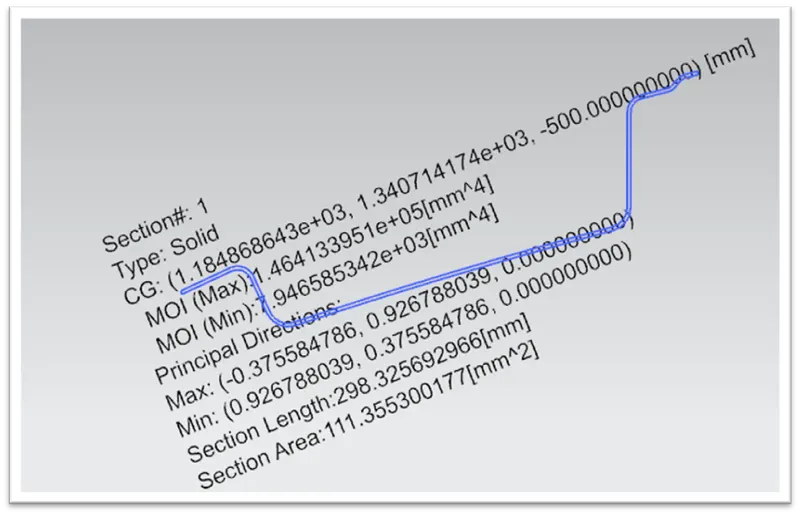
Moment of inertia (Max), Imax = 1.464 x 105 mm4
Moment of inertia (Min), Imin = 7.946 x 103 mm4
S = I/Y
Y = 62.2 mm
For maximum MOI,
S = 1.464 x 10⁵ / 62.2
SMAX = 2353.69 mm3
For minimum MOI,
S = 7.946 x 10³ / 62.2
SMIN = 127.74 mm3
REAR ROOF RAIL:
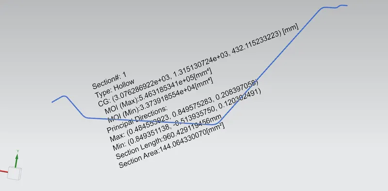
Moment of inertia (Max), Imax = 5.463 x 105 mm4
Moment of inertia (Min), Imin = 3.373 x 104 mm4
S = I/Y
Y = 96.725 mm
For maximum MOI,
S = 5.463 x 10⁵ / 96.725
SMAX = 5647.97 mm3
For minimum MOI,
S = 3.373 x 10⁴ / 96.725
SMIN = 348.72 mm3
DRAFT ANALYSIS:
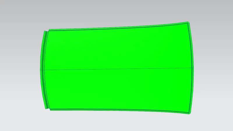
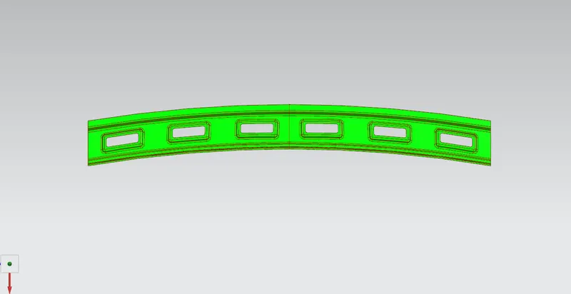
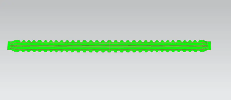
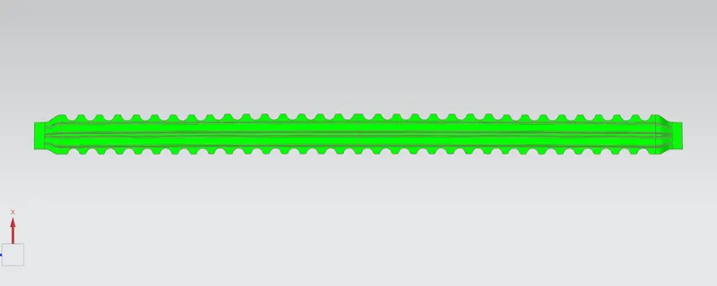
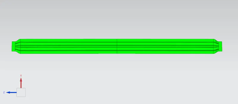
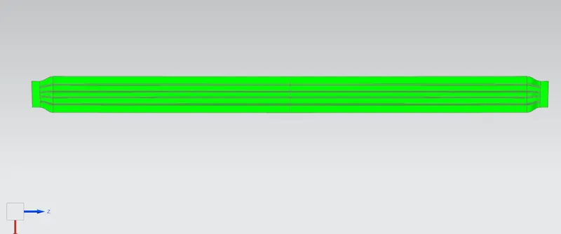
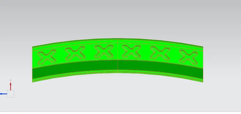
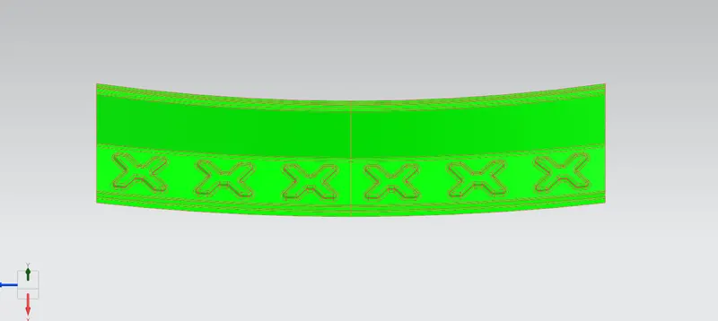
The Draft Analysis command enables you to detect if the part you drafted will be easily removed. This type of analysis is performed based on color ranges identifying zones on the analyzed element where the deviation from the draft direction at any point, corresponds to specified values.
Minimum draft angle is 7 degree is considered for analysis. Green colour show positive draft angle of the part more than 7 degree.
ROOF OUTER PANEL:
FRONT ROOF RAIL:
BOW ROOF FRONT -
BOW ROOF REAR -
CENTRE ROOF RAIL -
REAR ROOF RAIL -
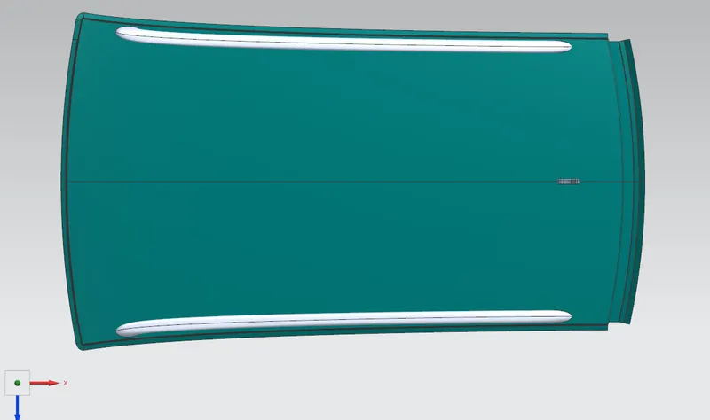
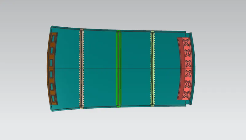
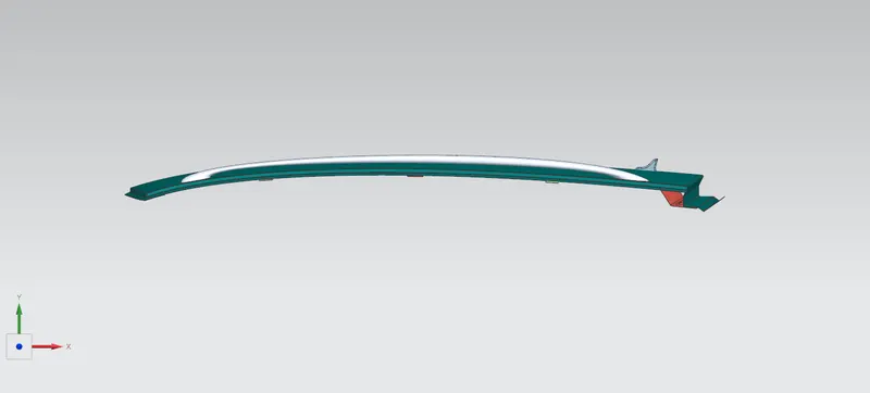
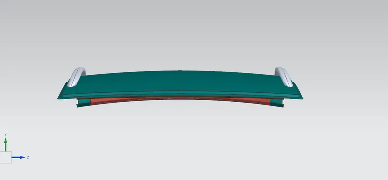
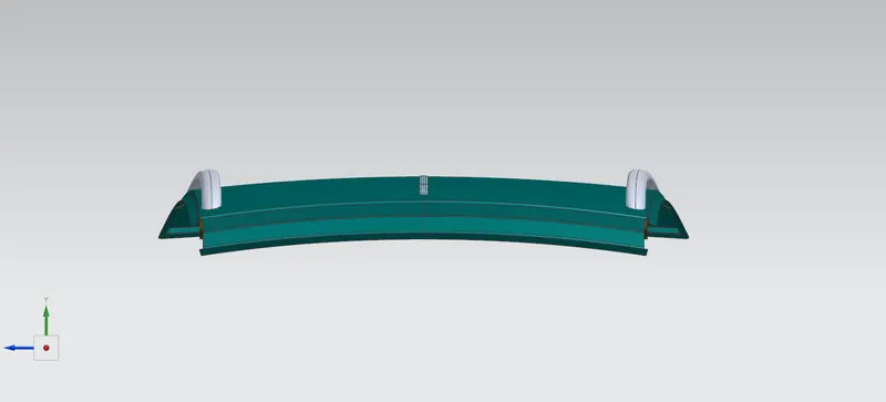
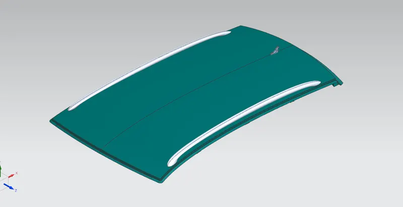
DIFFERENT VIEWS OF THE ROOF -
CONCLUSION:
I did the My roof design and check heat distortion and snow load condition for bow roofs are placed at right place or not. So, after finishing my design I did the heat distortion and snow load condition.
After, finishing the curvature study. Then go to check the section modulus. And last, we check the draft analysis. Because, whether part is manufacturable or not. That, why we doing this analysis. That’s all my design pass the all requirements for placing the roof on the car.