Roof Design
Roof Design
Challenge:
- For the Given Roof styling, create an ASSEMBLY by developing the essential flanges for the outer roof and creating the reinforcements.
- Provide appropriate dimensions and check for Draft analysis.
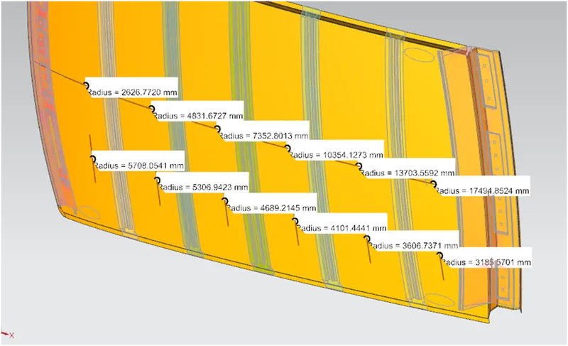
- Do a curvature study on the roof and perform calculations to determine the position of the Bow-roofs.
- Suggest and implement remedies in the design if the criterion is not full-filling
- Start with the creation of a roof ditch area with a tool opening angle of 7 degrees.
- Develop the reinforcements as separate parts
Roof:
A car roof is an enclosure on the top of a car to protect the passengers from sun light, rain, dust, etc., by providing safety and comfort to the passengers.
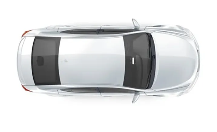
Types of Roof:
1. Hardtop:
The hardtop roofs are generally used in most of the cars with metal to provide strength of the car. The hardtop roofs are of three types:
a. Non-detachable hardtop:
Most of the cars are of hardtop roofs which are non-detachable and fixed on the car.
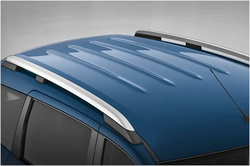
b. Detachable or retractable hardtop:
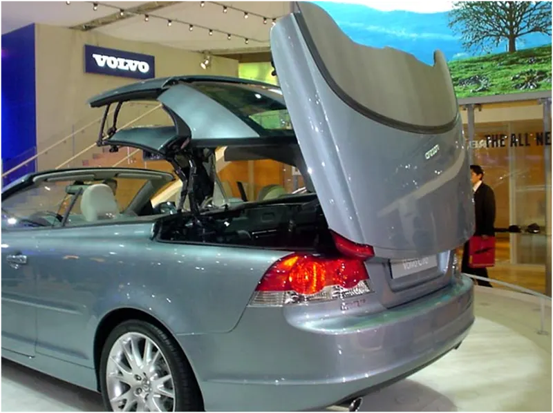
Only few of the cars have detachable or retractable hardtop roofs, which can be detached or retracted as per passengers comfort.
c. Pillarless hardtop:
The cars without B-pillar and short roof designed as pillarless roof which doesn’t have glass frame for windows. These type of hardtops are designed for aesthetic, luxurious and stylish looks.

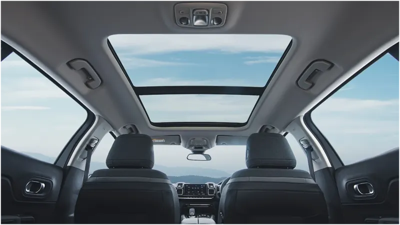
2. Sun roofs:
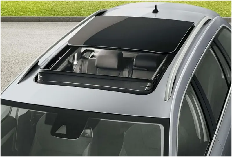
Sun roofs are sliding glass panels using motors by allowing sunlight and fresh air through small area while travelling. Those glass panels are transparent or tinted to view the outer area. Earlier it is also termed as moon roof.
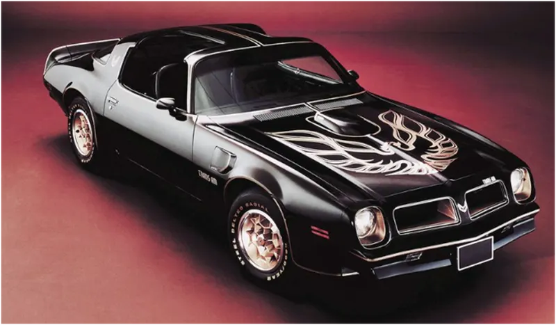
3. T- top roof:
The T-top roof of an automobile is a rigid bar mounted between centres of the structural bars. For T-top roof safety glasses were mounted on the roof on both sides of the rigid bar.
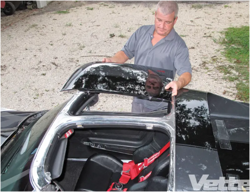
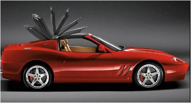
4. Targa top roof:
Targa top roof is a semi convertible type comes with fixed metal rises up from one side, over the roof and down the other side. It is a type of wrap over band which comes from rear rail of the roof to the front roof rail.
5. Vinyl roof:
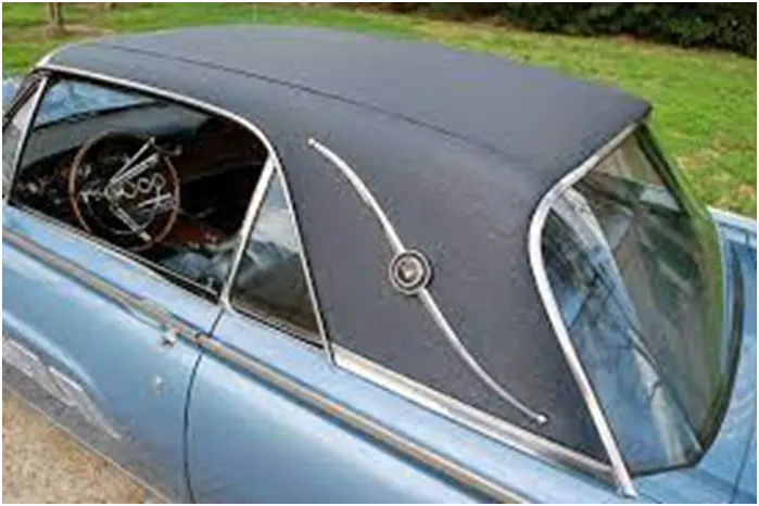
Vinyl roof refers to plastic roofs that are used in car roof top for luxury look. The term vinyl in car roof refers to poly vinyl chloride or plastic.
Design of a non-detachable hardtop:
A non-detachable hardtop should be designed in such a way that it should consists of front roof rail, rear roof rail, centre reinforcement rail and additional bow roof rails for additional support for a roof. All the above mentioned rails should be designed as per two important conditions:
a. Bow-roof prediction formula or heat distortion formula:
W = [1.73 x 10⁻³ x L] + [1.85 x 10⁻⁸ x (R2)/t] + [1.10x10⁻³ x l] - 2.68
Where,
L = Roof Length in X-Direction[mm](Roof dimension in 0-Y)
R = Roof curvature
R = 2(Rx x Ry)/( Rx + Ry)
Rx = X curvature
Ry = Y curvature
t = Roof plate thickness [mm]
l = Bow Roof Span [mm]
Judgement condition:
OK<2.7
b. Snow-load prediction formula:
Qr = [ly x t2] / [α x s x [(Rx + Ry)/2]2 x 10-8]
Where,
α = My x Lx2 x 10-12 , My = Y(Ly-Y)
t = Roof plate thickness [mm]
Ly = Distance between the front and rear roof Rails on the Vehicle along with 0-Y[mm]
Length of Roof panel with the center point between Roof rail Front /Rear as the front and rear reference point.
Lx = Distance between the Left and Right end of the roof on the Roof BOW [mm]
The width of the roof panel is exposed on the surface.
Y = Distance front Front Roof Rail to Roof BOW[mm]
s = Distance for which Roof BOW bears divided load [mm]
s = L1/2 + L2/2
Iy = Geometrical moment of inertia of Roof BOW (Y cross-section )[mm4]
Rx = Lateral direction curvature radius of roof panel Y cross-section on Roof BOW [mm]
Roof panel curvature Radius of the Length Lx in Front view
Ry = Longitudinal Direction curvature radius of the Roof panel X cross-section on Roof BOW [mm]
Roof panel X curvature radius of length s in Side view
Judgement condition:
Qr ≥ 3.1
250 ≤ s ≤ 380
Procedure for designing roof and its components:
The roof can be designed by using provided skin data and the master sections for front roof rail, rear roof rail, centre reinforcement structure and bow roof rails.
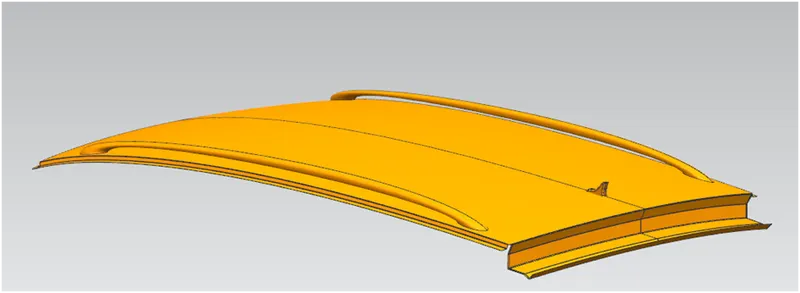
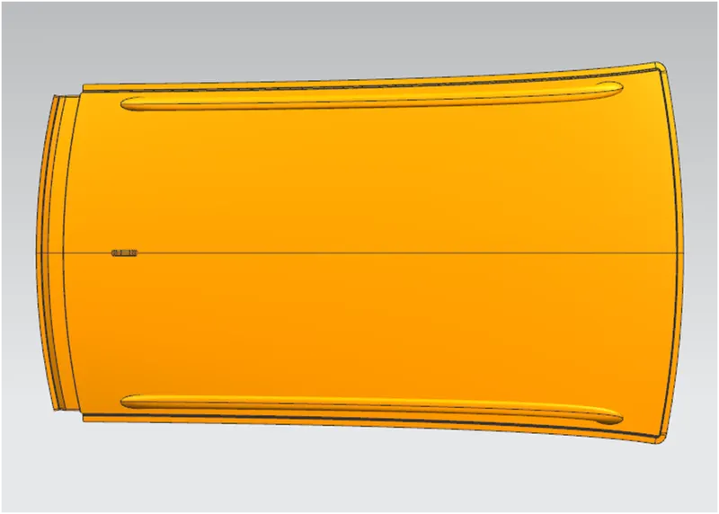
- Outer roof panel:
By using the provided skin data, outer roof panel to be designed using front roof rail master section and rear roof rail master section.
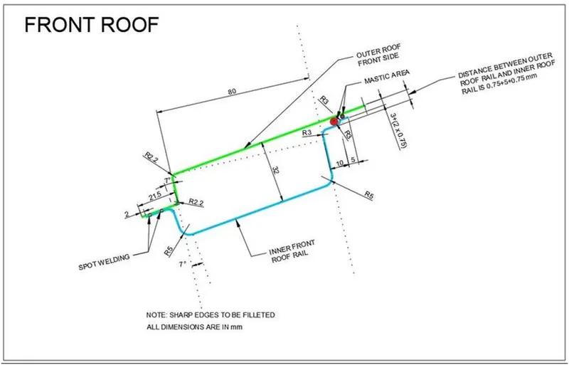
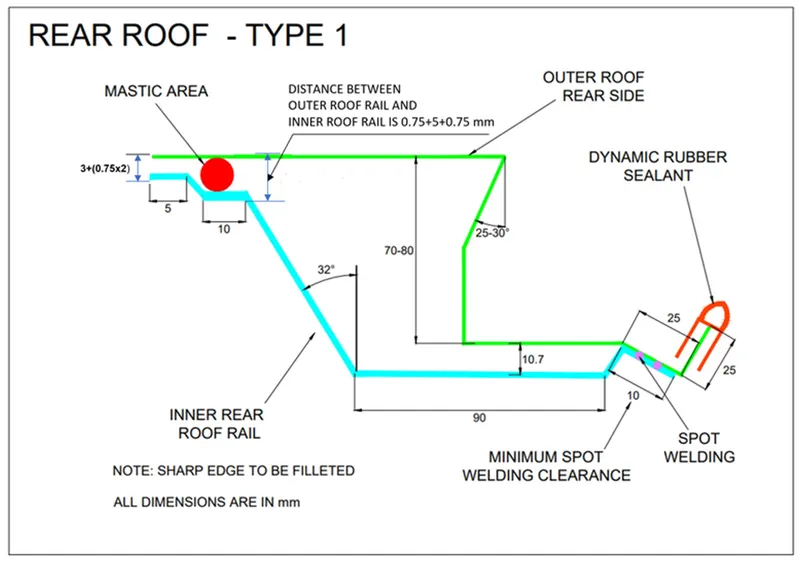
The outer panel is designed using following tools in NX to achieve the above master sections.
- Offset surface
- Extend sheet
- Law Extension
- Trim and Extend
- Curve on surface
- Trim sheet
- Offset in face
- Edge blend
- Studio surface
- Sweep
- Mirror geometry
- Sew
- Thicken
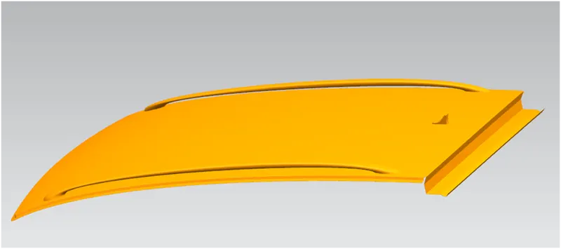
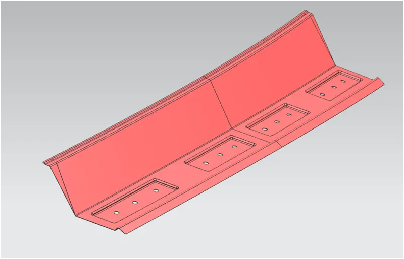
- Front Roof Rail (FR):
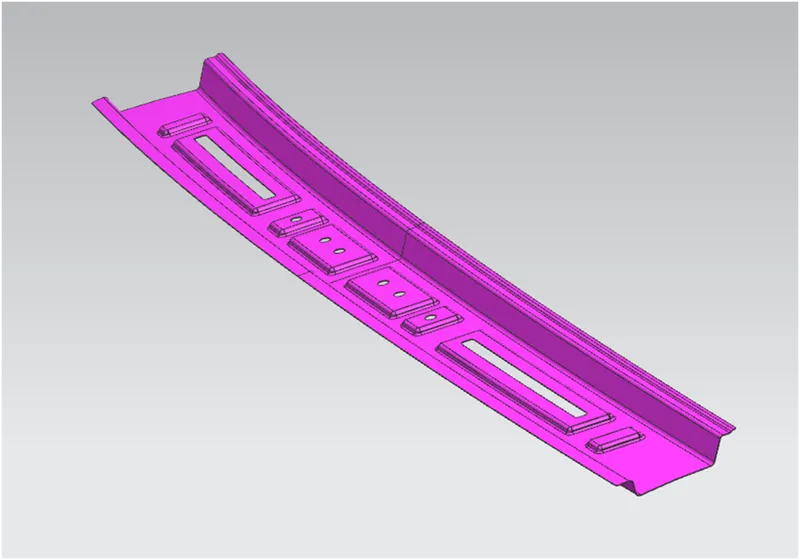
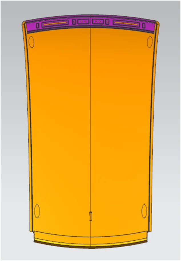
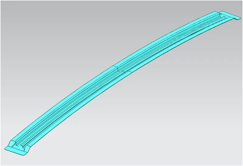
Front roof rail is one of the support structures of roof which connects between two A-pillar mounts. This front roof rail holds both roof and windshield of a car. The front roof rail of a car can be designed by using provided master section using following NX tools:
- Wave geometry linker
- Emboss
- same tools as outer panel
To increase the strength of the front roof rail and to reduce the weight of the material, emboss and cut-outs are provided.
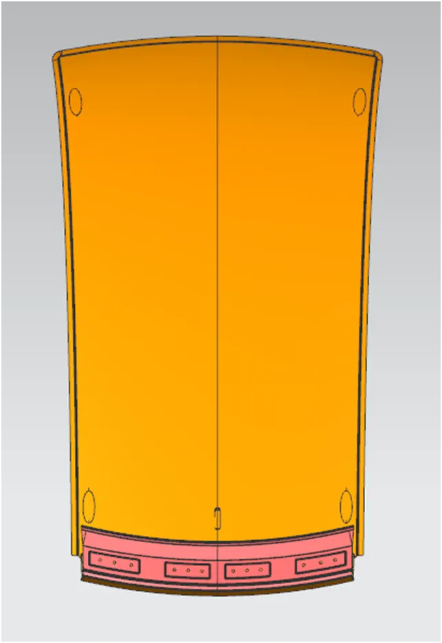
- Rear Roof Rail (RR):
Rear roof rail is one of the support structures of roof which connects between two C-pillar mounts. This rear roof rail holds both roof and tail gate of a car. The rear roof rail of a car can be designed by using provided master section using following NX tools:
- same tools as front roof rail
To increase the strength of the rear roof rail and to reduce the weight of the material, emboss and cut-outs are provided.
- Centre reinforcement roof rail (CR):
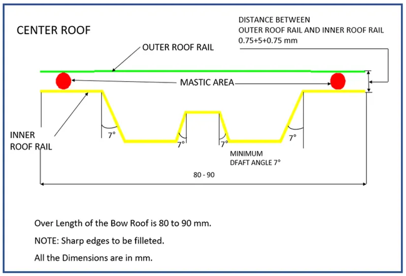
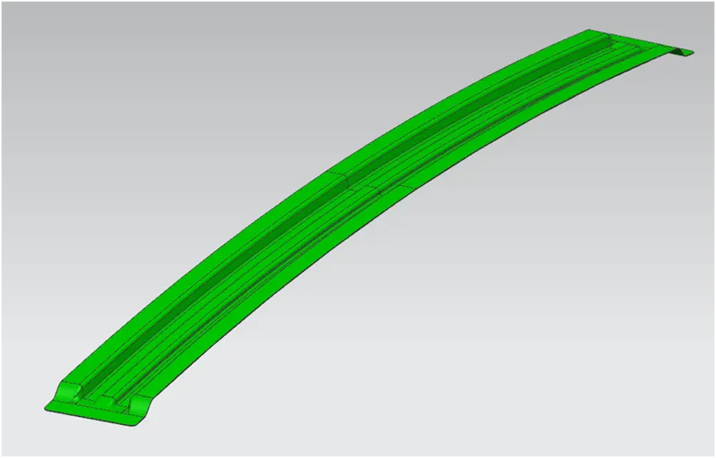
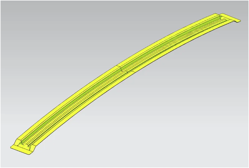
Centre reinforcement roof rail is one of the support structures of roof which connects between two B-pillar mounts. The centre reinforcement roof rail of a car can be designed by using provided master section using following NX tools:
- same tools as rear roof rail
Centre reinforcement roof rail to be designed with ditch area to spot weld with side frames of a car.
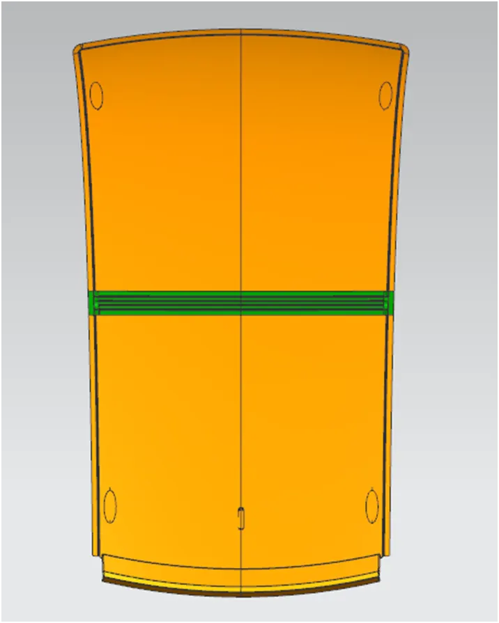
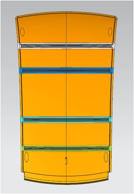
- Bow-roof rails (BR1 to BR4):
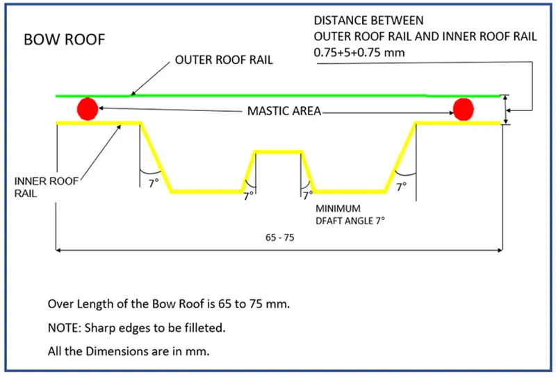
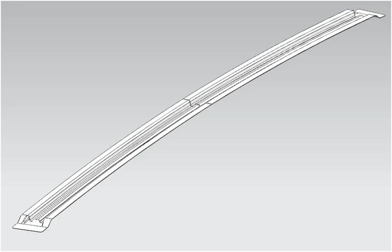
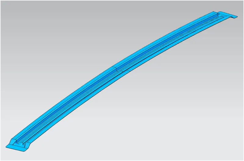
Bow roof rails are part of the support structures of roof for additional support connects in-between front roof rail and rear roof rail mounts. The bow roof rails of a car can be designed by using provided master section using following NX tools:
- same tools as centre reinforcement roof rail
Bow roof rails to be designed with ditch area to spot weld with side frames of a car. The count of bow-roof rails depends on bow-roof prediction formula or snow load prediction formula.
Bow-Roof prediction calculation for the provided model:
W = [1.73 x 10⁻³ x L] + [1.85 x 10⁻⁸ x (R2)/t] + [1.10x10⁻³ x l] - 2.68
Where,
L = Roof Length in X-Direction[mm](Roof dimension in 0-Y)
R = Roof curvature
R = 2(Rx x Ry)/( Rx + Ry)
Rx = X curvature
Ry = Y curvature
t = Roof plate thickness [mm]
l = Bow Roof Span [mm]
|
S. No. |
Location Between |
L (mm) |
RX (mm) |
RY (mm) |
R (mm) |
t (mm) |
l (mm) |
R2/t (mm) |
W |
Status |
|
1 |
FR & BR1 |
2142 |
5708 |
2627 |
3598.06 |
0.75 |
266 |
17261383 |
1.61 |
OK |
|
2 |
BR1 & BR2 |
2142 |
5307 |
4832 |
5058.373 |
0.75 |
230 |
34116189 |
1.87 |
OK |
|
3 |
BR2 & CR |
2142 |
4689 |
7353 |
5726.327 |
0.75 |
224 |
43721100 |
2.07 |
OK |
|
4 |
CR & BR3 |
2142 |
4101 |
10354 |
5875.026 |
0.75 |
222 |
46021248 |
2.11 |
OK |
|
5 |
BR3 & BR4 |
2142 |
3607 |
13703 |
5710.771 |
0.75 |
281 |
43483870 |
2.13 |
OK |
|
6 |
BR4 & RR |
2142 |
3186 |
17495 |
5390.365 |
0.75 |
201 |
38741381 |
1.96 |
OK |
Snow-load prediction calculation for the provided model:
Qr = [ly x t2] / [α x s x [(Rx + Ry)/2]2 x 10-8]
Where,
α = My x Lx2 x 10-12 , My = Y(Ly-Y)
t = Roof plate thickness [mm]
Ly = Distance between the front and rear roof Rails on the Vehicle along with 0-Y[mm]
Length of Roof panel with the center point between Roof rail Front /Rear as the front and rear reference point.
Lx = Distance between the Left and Right end of the roof on the Roof BOW [mm]
The width of the roof panel is exposed on the surface.
Y = Distance from Front Roof Rail to Roof BOW [mm]
s = Distance for which Roof BOW bears divided load [mm]
s = L1/2 + L2/2
Iy = Geometrical moment of inertia of Roof BOW (Y cross-section) [mm4]
Rx = Lateral direction curvature radius of roof panel Y cross-section on Roof BOW [mm]
Roof panel curvature Radius of the Length Lx in Front view
Ry = Longitudinal Direction curvature radius of the Roof panel X cross-section on Roof BOW [mm]
Roof panel X curvature radius of length s in Side view
Judgement condition:
Qr ≥ 3.1
250 ≤ s ≤ 380
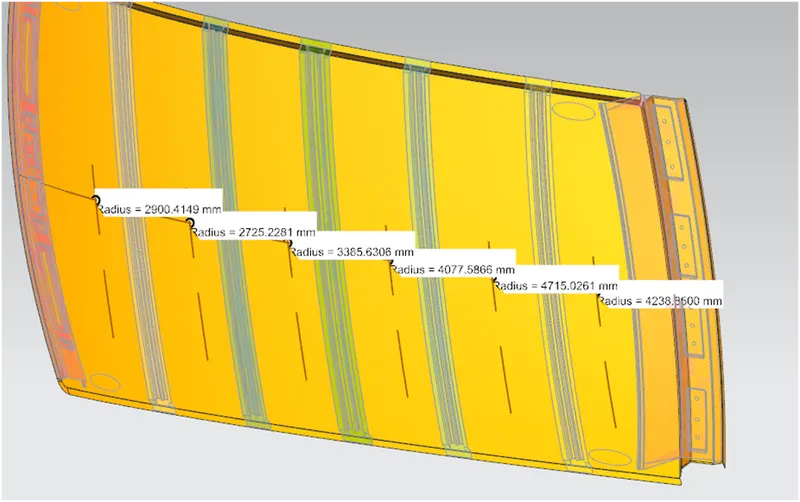
|
S. No. |
Location Between |
ly (mm4) |
RX (mm) |
RY (mm) |
My (mm) |
t (mm) |
α (mm) |
s (mm) |
Qr |
Status |
|
1 |
FR & BR1 |
3876 |
2900 |
2627 |
698141 |
0.75 |
0.9 |
353 |
90 |
OK |
|
2 |
BR1 & BR2 |
3909 |
2725 |
4832 |
1013816 |
0.75 |
1.3 |
305.5 |
39 |
OK |
|
3 |
BR2 & CR |
4505 |
3386 |
7353 |
1143560 |
0.75 |
1.4 |
305 |
21 |
OK |
|
4 |
CR & BR3 |
3929 |
4077 |
10354 |
1087016 |
0.75 |
1.3 |
330 |
10 |
OK |
|
5 |
BR3 & BR4 |
3932 |
4715 |
13703 |
785840 |
0.75 |
0.9 |
357.5 |
8 |
OK |
|
6 |
BR4 & RR |
NA |
4239 |
17495 |
225441 |
0.75 |
0.2 |
NA |
NA |
NA |
Draft Analysis:
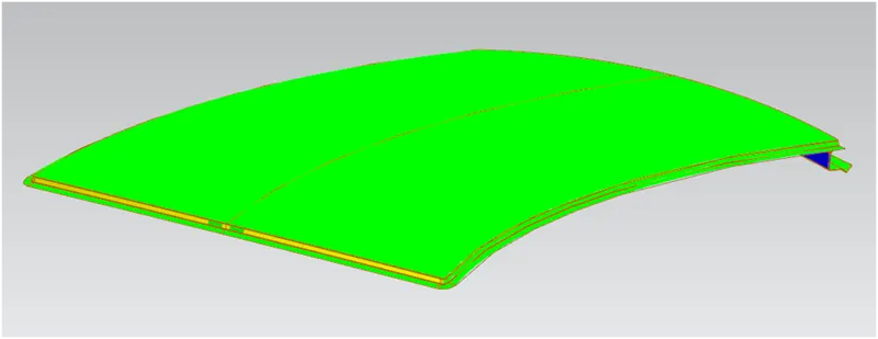
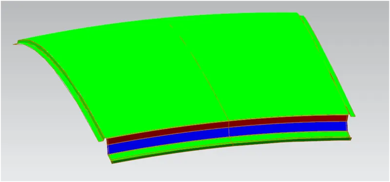
Draft analysis is a method to determine the product is having positive draft while moulding or deep drawing. If the product is having negative draft angle, tool cannot be removed from die and conversely if the product is having positive draft angle, tool can be removed from die easily without any damages or tear in the part. Draft analysis to be performed to check whether the part is having positive draft or negative draft, so designers can give alternate solution for the part to achieve positive draft.
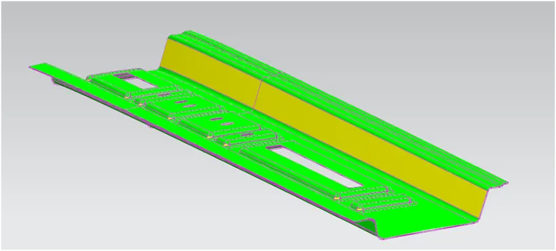
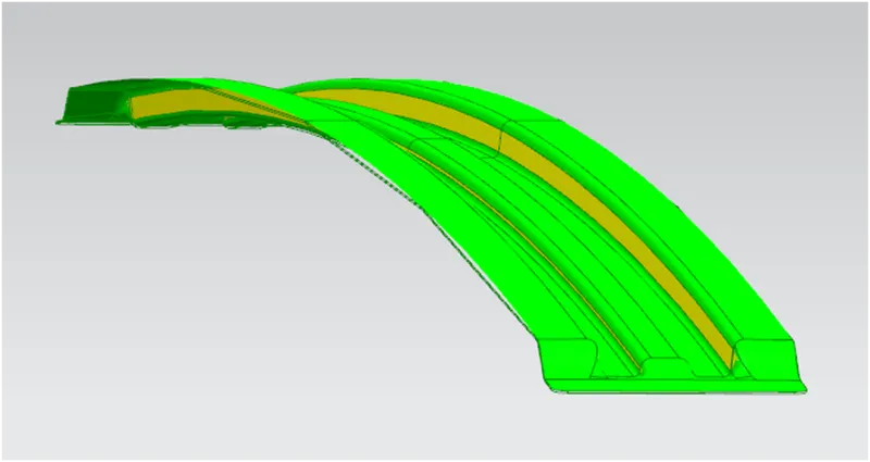
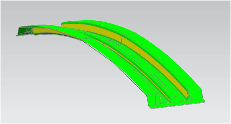
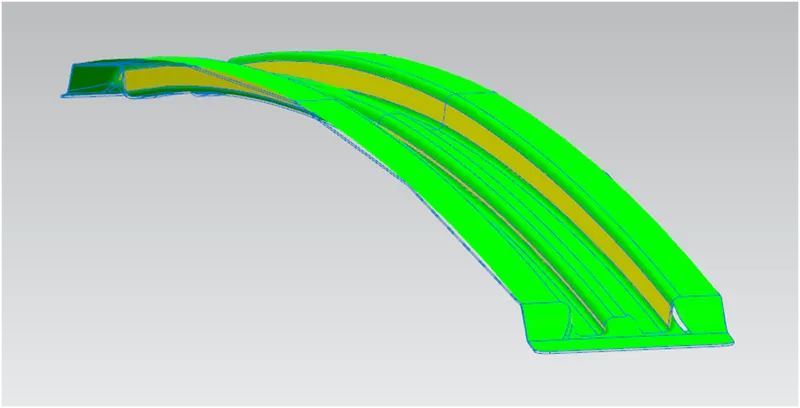
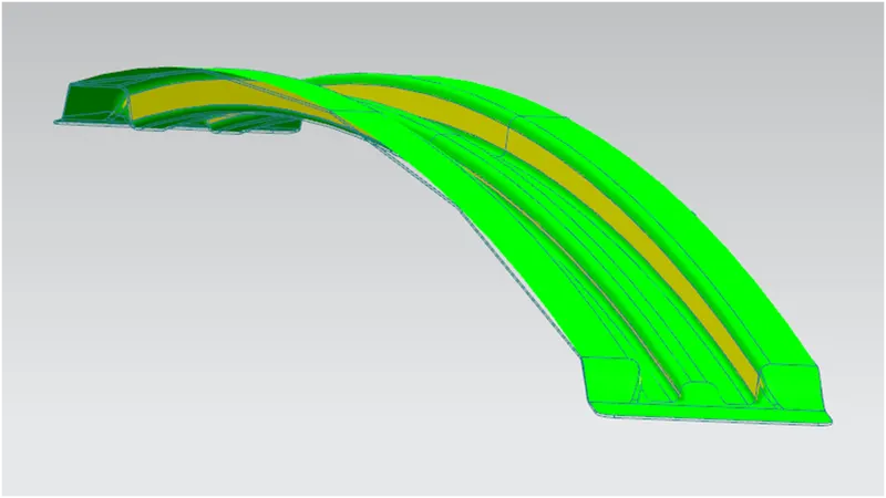
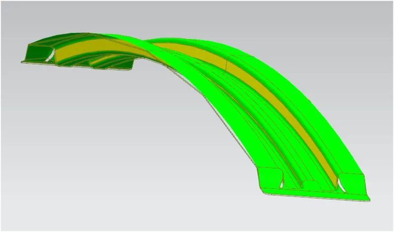
For the provided skin data, draft analysis has been performed and all the parts in it is having positive draft, so the parts can be easily manufactured for emboss and cut-outs. Images for all the parts with draft analysis are attached for clear view about draft analysis.
Draft analysis for below components:
a. Outer Panel:
For Outer panel, it shows some faces with positive draft angle and some faces with negative draft angle. For those places where it is shown as negative draft angle are manufactured by sheet metal bending method by using press brake design.
b. Front roof rail:
Front roof rail is having positive draft angle and it can be manufactured easily without any wear.
c. Rear roof rail:
Rear roof rail is having positive draft angle and it can be manufactured easily without any wear.
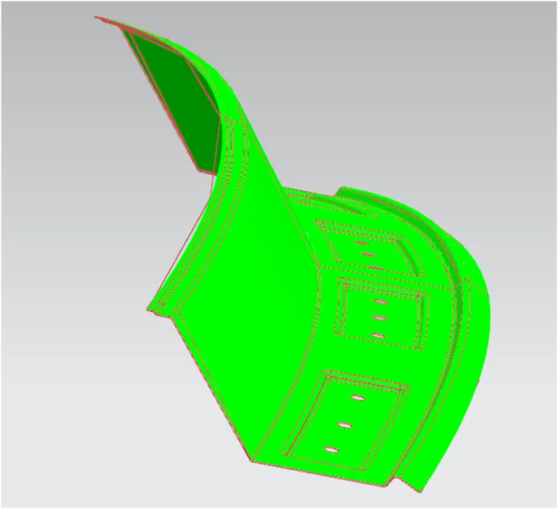
d. Centre reinforcement:
Centre reinforcement is having positive draft angle and it can be manufactured easily without any wear.
e. Bow-roof rail 1 to 4:
Bow roof rails are having positive draft angle and those can be manufactured easily without any wear.
Conclusion:
- From the provide roof styling, assembly has been created with essential flanges for the outer roof by creating the reinforcements.
- Draft analysis has been done for all the components and positive draft has been achieved.
- Curvature study has been done for the bow-roof position by creating 4 number of bow-roofs for additional supports.
- By performing curvature study for bow –roof prediction and snow load calculation, all the design criteria has been achieved.
- Roof ditch area has been created with tool opening angle of 7 degrees.
- Centre reinforcement has been created as a separate part.