Roof Design
AIM : For the Given Roof styling, create an ASSEMBLY by developing the essential flanges for the outer roof and creating the reinforcements.
Objectives :
1) To design the automotive roof based on the Given Roof styling, create an ASSEMBLY by developing the essential flanges for the outer roof and creating the reinforcements.
2) Provide appropriate dimensions and check for Draft analysis.
3) Do a curvature study on the roof and perform calculations to determine the position of the Bow-roofs.
4) Develop the reinforcements as separate parts
5) Suggest and implement remedies in the design if the criterion is not full-filling
Introduction :
An automotive roof is the top portion of the automobile that sits above the pasenger compartement, protectting the pasengers from the sun, wind, rain, snow and other external elements.
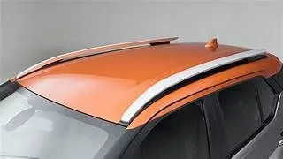
As we see in the above image, roof is having many structural elemnts such as bow roof rails, centre roof , rear roof, front roof , centre roof reinforcement, sun roof. these all component provides strength to the oter roof so they are neccesory to omprove the strength, and to attach the roof to the other components of the car by using mastics , spot welding. the bow roofs and reinforcements are always provide on the flate surfsce to enhance its strength to increase the stregth of the roof elemenys. and there by imroving the NVH value so increasing the strength of the roof using the mastic sealants.
Types of roofs :
1. convertible roofs
2. hard roof
3. sun roofs
4. tangent tops
5. target roof
6. vinyl roof
Design consideration of roof
- Visibility creteria
- Head clearance
- curavtaure study
- Heat distortion and snow load creteria
- Draft analysis
- Safety parameters
- Section modulus study
Joining process:
mastic sealant and the spot welding is used to join the components
Reinforecements and its types:
If the roof is flat then it is weak and cannlot be able to stand the external load like snow and while crash. In order to increase the styrength the reinforcements are attcahed such as front roof rail, rear roof rail, centre roof rail, centre roof inforcements, bow roof rails with tyhje helps of joining process like mastics or spot welding. These roof reinforcemts types are discussed in details below.
- front roof rail
- rear roof rail
- bow roof rails
- centre roof rail
Roof oter panel:
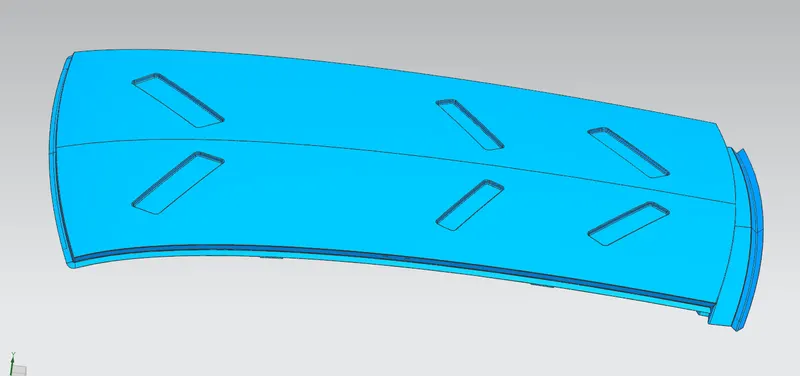
Outer roof panel is created in the Nx as shown the above figure. The outer roof is created as per the design rules and as per the master section and styling surface given. the embosis are created as shown in figure to enhance the strength of the outer roof panel.
Front roof rail :
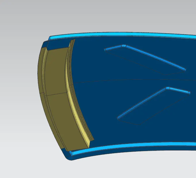
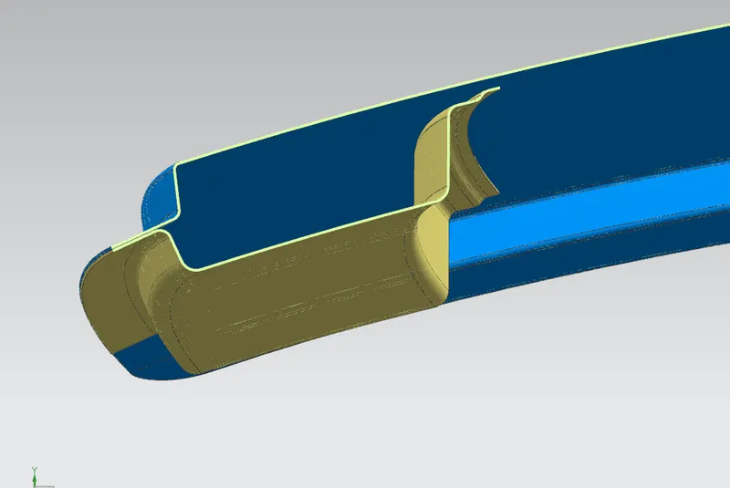
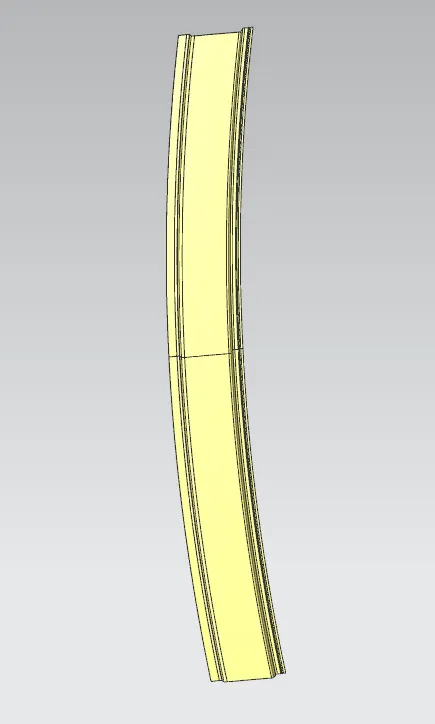
front roof rail joins the wind shield glass, body side outer and inner panel also. the is the front roof rail is designed as per the master section given. it also designed by considering front visiblity. front pasengers headroom clearance is also considered while deisgning. also clip sections are proved to get detailed view.
Rear roof rail
rear roof aril alos works as same as front roof. rear roof provides the reinforcement to the rear part of the car. it also designed by considering rear visiblity. rear pasenger headroom clearance. the is the raer roof rail is designed as per the master section given. also clip sections are proved to get detailed view.
Bow roof rail
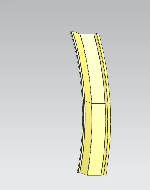
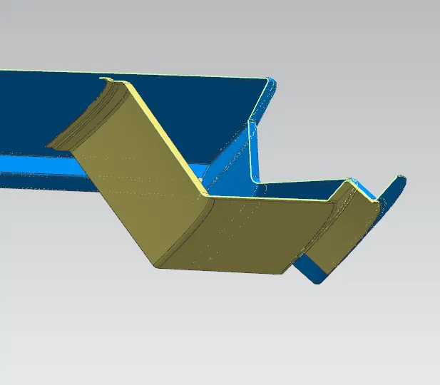
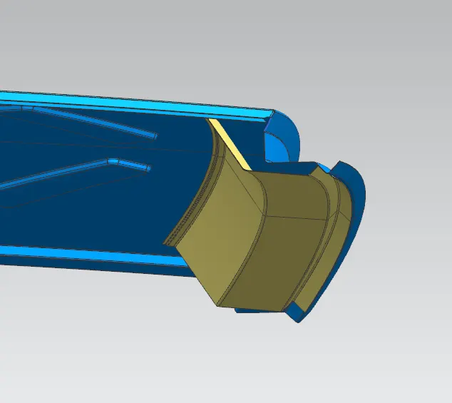
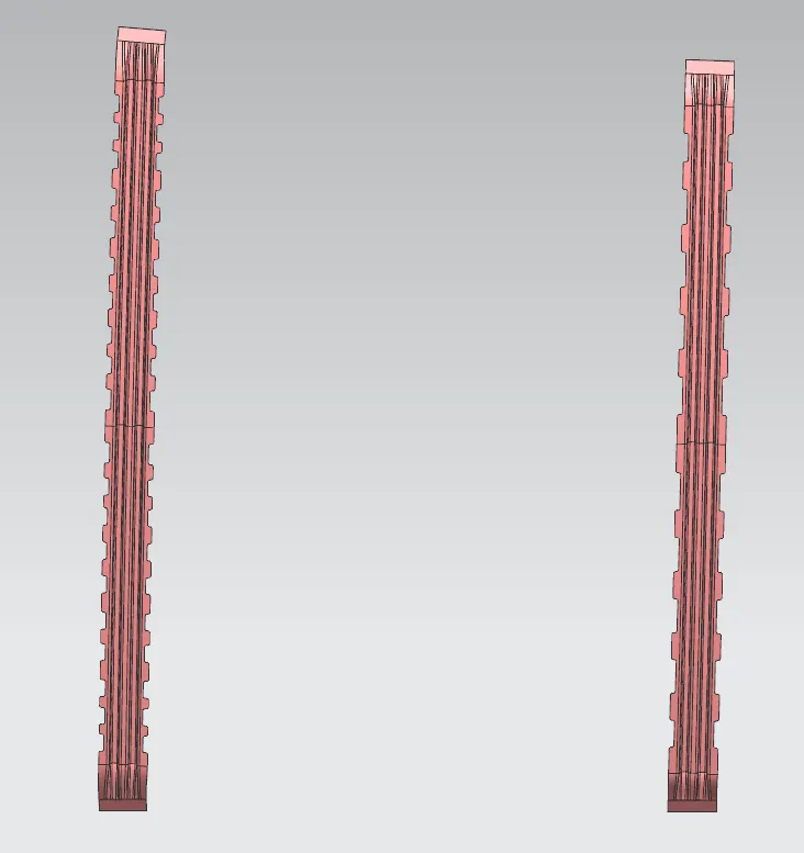
Gow roof s are given to enhance the stregth of the outer roof rail. they are given at the flate surface only to improve efficeintly. and it position is determined by using the heat distortion study and snow load condition study. this study predicts the exact correct position of bow roof so that the bow roof works efficiently to improve the strength of theouter roof panel. also the curavature study is done using these above mentioned studies.
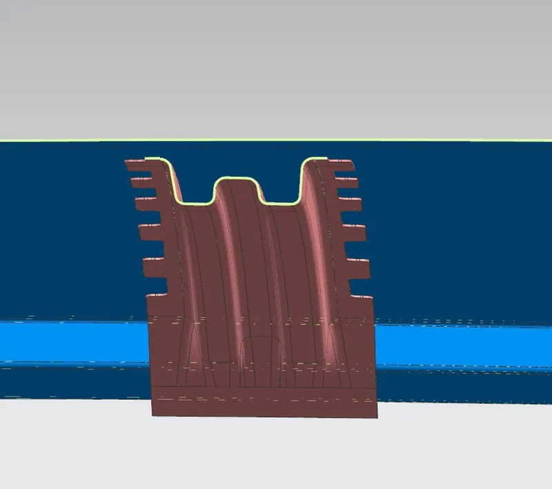
Generally bow roof are given in two or three or one in numbers according to thr requirements. and they are provide at the flate surface. they are disigned as the master sections and reinforecemts are provided are are joined using the mastics and spot welding. the cutouts are provide to place the mastics. also clip sections are proved to get detailed view.
Centre roof with reinforcement :
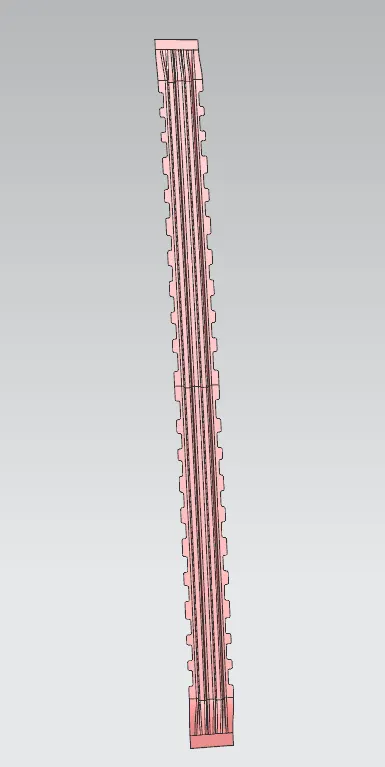
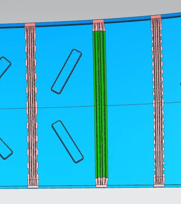
centre roof rail is helps in providing the supprt to the flate area of the outer panel. generally centre roof rail is provide at the centre of the outer panel. entre roof rail generally helps in providing strength to the roof during the roll over study. also is attche dusinf the centre roof aril reinforecet as show in the figure. it is designed using the given master section and the also clip section vie is given to get detaide view.
Most im[ortamtly the centre roof rail and centre roof reinforecemnt are designed as seperate part and joined by using the spot welding anf mastics with outer roof.
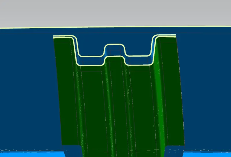
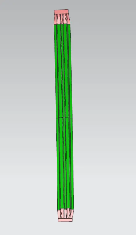
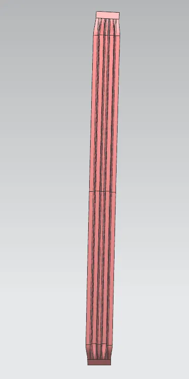
Images of difrent view of whole roof assembly :
1) Top view
2) Bottom view
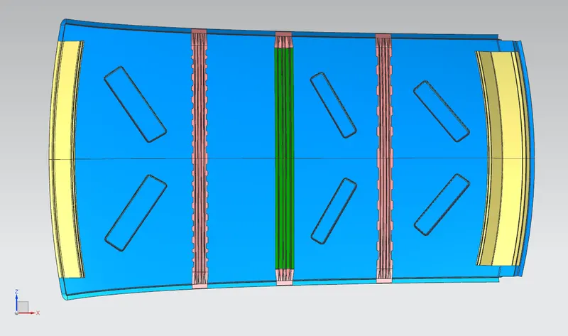
3) clip sectional view
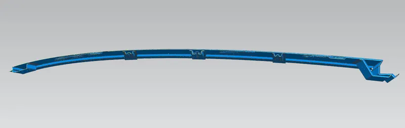
4) isometic view
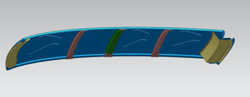
Design calculation of roof for the bow roof position and to check the strength analysis and curvature analysis
1 . Heat distortion study
2. snow load condition study
1. Heat distortion study
Heat distortion study palys a important role in the sheel meatl ussage. heat distortion teperature is the temerature limit which the above material cannot be used as the material for structural applications.Means the above heat distortion temperature metal softens and deformes under load. this study is used to predict the heat distortion teperature at the material where it start to soften when exposed to fixed load at elevated tempoerature. in oredr to avoide the bending or the damages on roof. based on the heat distortion temrprature will predicts the bow roof position which helps to strengthen the roof.
Bow–Roof Prediction Formula
W = [1.73 x 10^(-3) x L] + [1.85 x 10^(-8) x (R^2)/t] + [ 1.10x10^(-3) x l] - 2.68
Where,
L = Roof Length in X-Direction[mm](Roof dimension in 0-Y)
R = Roof curvature
R = 2(Rx*Ry)/(Rx+Ry)
Rx = X curvature
Ry = Y curvature
t = Roof plate thickness [mm]
l = Bow Roof Span [mm]
Judgment Condition
OK< 2.7
measure the required values and calculate the value of W and check the condition.
Over all roof length
L= 2138.71 mm
t = Roof plate thickness [mm]
t= 0.75 mm
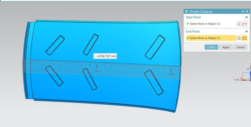
Bow Roof Span [mm]
l = 1141.52
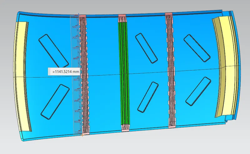
R = Roof curvature
ProcedureTo find values of RX and RY and R For heat distortion creteria
- we need to create the sketch on the top of outer roof panel, draw a line at centre of roof in o-y axis ( mid horizontal line)
- next draw a line by 300 mm dustance above and below of centreline and make them construction line.
- draw a line perpendicular to the centreline passing throgh a exact mid point of ywo adjacent parts ( midpoint between front roof rail and the bow roof rail 1 ). simmilarly for all parts. make it reference line.
- offset these reference line 100mm on both sides.
- mark intersection points at the intersection of the refernce lines with the 100mm offset lines.
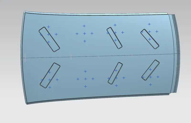
- then these intersection points are projected on the outer roof panel surface. to creat a curves to find the Rx and Ry values.
- R = 2(Rx*Ry)/(Rx+Ry)
Rx = X curvature
Ry = Y curvature
CREATE SKETCH
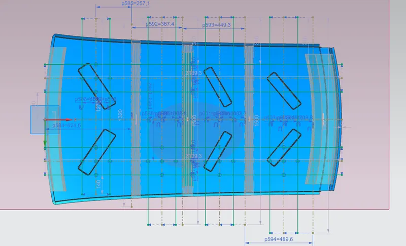
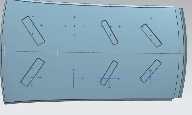
created intersection points
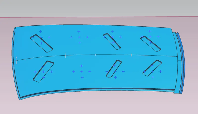
Intersection points projected on outer roof panel surface
measure RX and RY
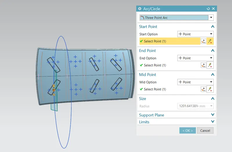
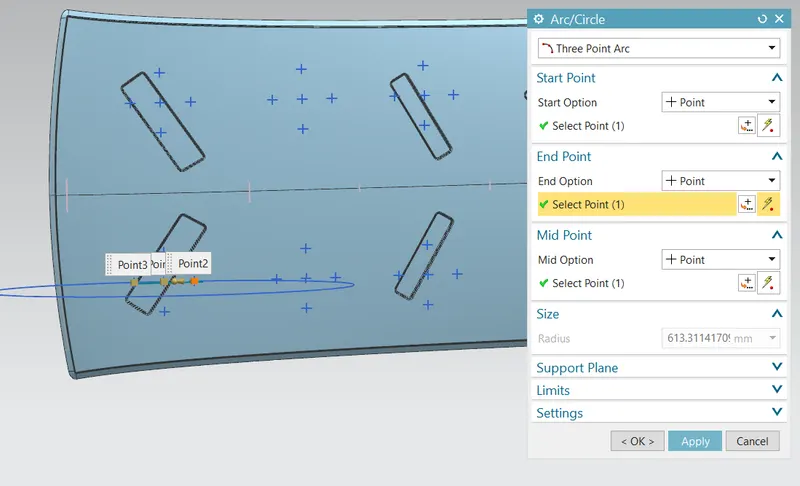
mesured rx ry for all span
Calculation and Heat distortion creteria data tabulated in below table
| Roof rail span | L (mm) | Rx | Ry | R | t (mm) | I (mm) | W | Result |
| Front roof and bow roof 1 | 2138.71 | 1201.64 | 613.31 | 812.13 | 0.75 | 526.25 | 1.6150 | pass |
| bow roof 1 and centre roof | 2138.71 | 4835.61 | 6779.24 | 5644.77 | 0.75 | 371.96 | 2.2150 | pass |
| centre roof and bow roof 2 | 2138.71 | 802.277 | 10321.68 | 1488.83 | 0.75 | 434.47 | 1.5524 | pass |
| bow roof 2 and rear roof | 2138.71 | 768.513 | 932.8618 | 842.74 | 0.75 | 530 | 1.62041 | pass |
Judgment Condition
OK< 2.7
So all the values are below the 2.7 i.e ( 1.610, 2.2150, 1.5524, 1.62041 are less than 2.7 ) so these bow roof positions are safe to be used. All bow roof passed the heat distortion creteria.
2. snow load condition study
This study is done to know how the roof is behaving when there is snow is over the roff. due to snow weight the dent will happen. but the roof should be designed in such a way that when the snow is removed the roof should go back to the original position. this is basic requirement for the snow load creteria.
Snow Load Prediction Formula
Qr = [Iy x t2] / [α x s x [(Rx + Ry)/2]2 x 10-8]
Note: The Qr value given over here is correct. There was a typo error in the formula given in the video.
Where,
α = My x Lx2 x 10-12 , My = Y(Ly-Y)
t = Roof plate thickness [mm]
Ly = Distance between the front and rear roof Rails on the Vehicle along with 0Y[mm]
Length of Roof panel with the center point between Roof rail Front /Rear as the front and rear reference point.
Lx = Distance between the Left and Right end of the roof on the Roof BOW [mm]
The width of the roof panel is exposed on the surface.
Y = Distance front Front Roof Rail to Roof BOW[mm]
s = Distance for which Roof BOW bears divided load [mm]
s = L1/2 + L2/2
Iy = Geometrical moment of inertia of Roof BOW (Y cross-section )[mm4]
Rx = Lateral direction curvature radius of roof panel Y cross-section on Roof BOW [mm]
Roof panel curvature Radius of the Length Lx in Front view
Ry = Longitudinal Direction curvature radius of the Roof panel X cross-section on Roof BOW [mm]
Roof panel X curvature radius of length s in Side view
Judgment condition
Qr ≥ 3.1
250 ≤ s ≤ 380
t = Roof plate thickness [mm]
t=0.75 mm
R = Roof curvature
ProcedureTo find values of RX and RY and R For heat distortion creteria
- we need to create the sketch on the top of outer roof panel, draw a line at centre of roof in o-y axis ( mid horizontal line)
- draw a line perpendicular to the centreline passing throgh a exact mid point of ywo adjacent parts ( midpoint between front roof rail and the bow roof rail 1 ). simmilarly for all parts. make it reference line.
- offset these reference line 100mm on both sides.
- mark intersection points at the intersection of the refernce lines with the 100mm offset lines.
- then these intersection points are projected on the outer roof panel surface. to creat a curves to find the Rx and Ry values.
Rx = X curvature
Ry = Y curvature
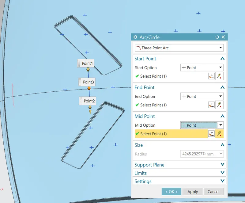
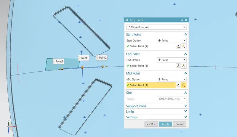
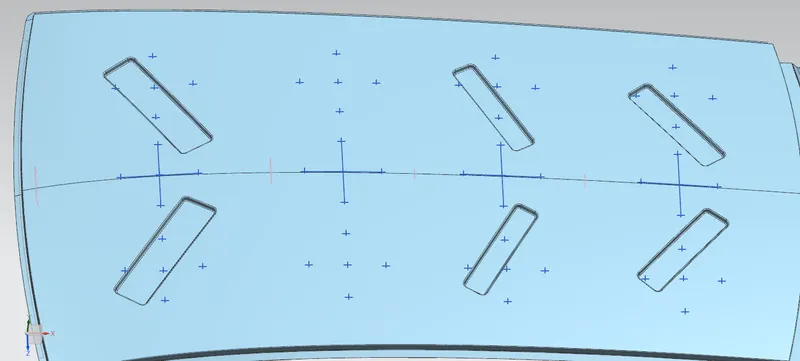
All the mesurements are required for the calcu;ation are mentioned above formulas and tabulated in below table.
Calculation and snow load creteria data tabulated in below table
| Rail roof span frm | Iy (mm4) | L1 | L2 | Ly | Lx | Rx | Ry | t | y | s | My | α | Qr | result |
| Front roof- BoW roof 1 | 2178.94 | 600 | 373.87 | 1815.55 | 1141.52 | 4245.29 | 3606.74 | 0.75 | 514.2 | 486.93 | 669154.17 | 0.8719 | 18.61 | pass |
| Bow roof 1 - cENTRE ROOF | 2606.439 | 373.87 | 442.87 | 1815.55 | 1094.64 | 3806.33 | 6722.31 | 0.75 | 297.55 | 408.37 | 451680.9 | 0.5412 | 23.94 | pass |
| Centre roof - bow roof 2 | 2191.917 | 442.39 | 634 | 1815.55 | 1092.61 | 4250.15 | 10759.29 | 0.75 | 367.38 | 538.14 | 532028.695 | 0.6351 | 6.44 | pass |
Judgment condition
Qr ≥ 3.1
250 ≤ s ≤ 380
All the Qr values are above the 3.1 so all the roof are safe to position. i,e the Qr values 18.61, 23.94, 6.44 are above the 3.1 as shown in table.
Suggestion : acoording second condition ( 250 ≤ s ≤ 380 ). the Distance front Front Roof centre to Roof BOW1 shound be reduced so s value come within range of 250 ≤ s ≤ 380[mm]. in my case the s values are above 300mm ie 486.93, 408.37, 538.14 mm. these s values should be made witin range by reducing L1 and L2 values of respective roofs span.
Section modulus :
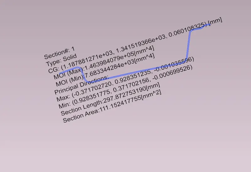
i) Section modulus of front roof rail
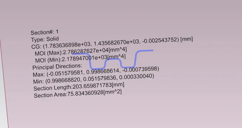
ii) Section modulus of bow roof 1
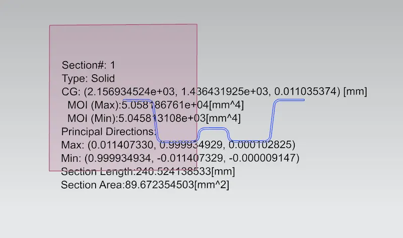
iii) Section modulus of centre roof
iv) Section modulus of bow roof 2
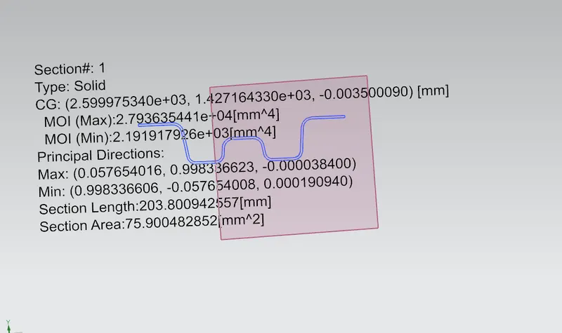
v) Section modulus of rear roof rail
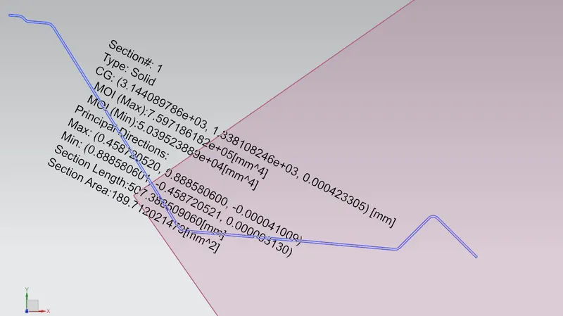
section modulus study :
| Roof rail span | Iy (mm4) | Y (mm) | S |
| Front roof | 7683.3 | 520 | 14.77 |
| Bow roof 1 | 2178.94 | 571 | 3.816 |
| centre roof | 5045.8 | 557.59 | 4.6744 |
| bow roof 2 | 2191.917 | 547.75 | 4.0016 |
| rear roof rail | 50395.238 | 469.81 | 107.26 |
Where,
Iy- MOI for section(min)
y- Distance of section from outermost fibre
S- Section modulus of section
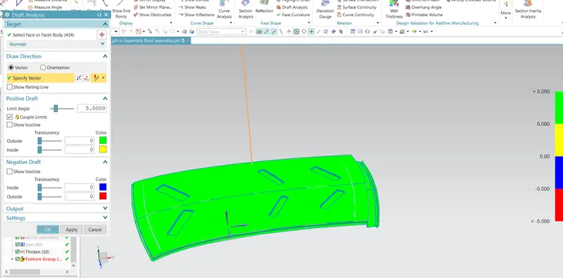
3) Draft analysis
Draft analysis for outer roof panel :
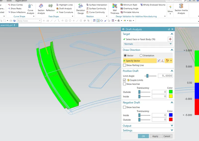
Draft analysis for front roof rail :
Draft analysis for rear roof rail :
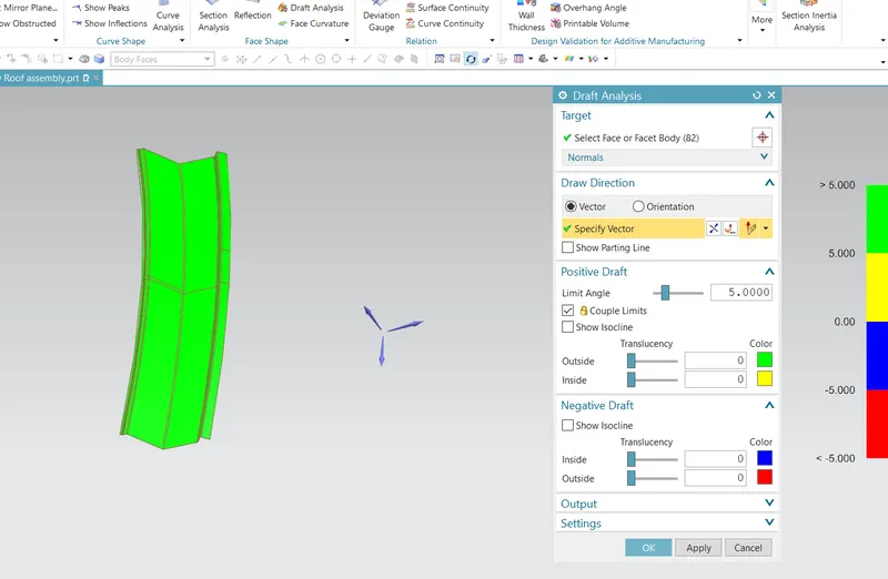
Draft analysis for centre roof rail :
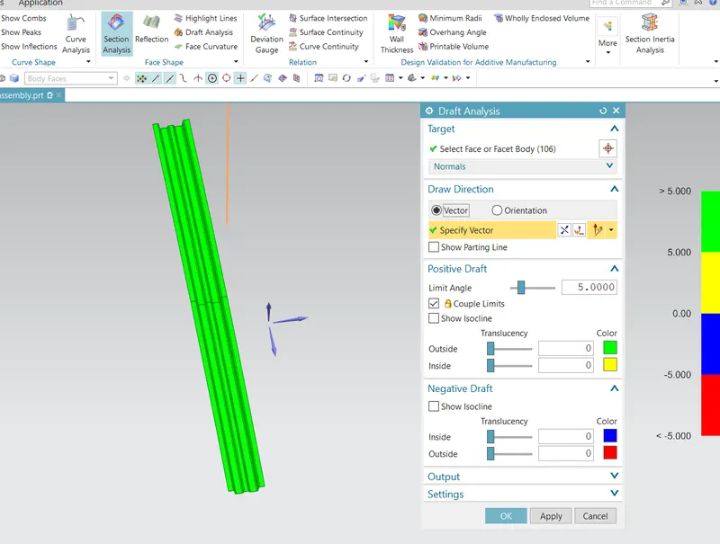
Draft analysis for centre roof reinforcement :
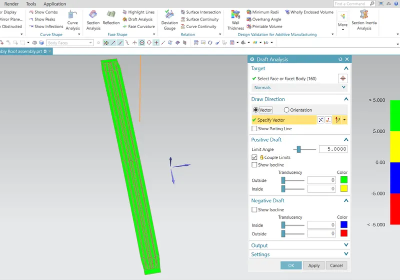
Draft analysis for bow roof 1:
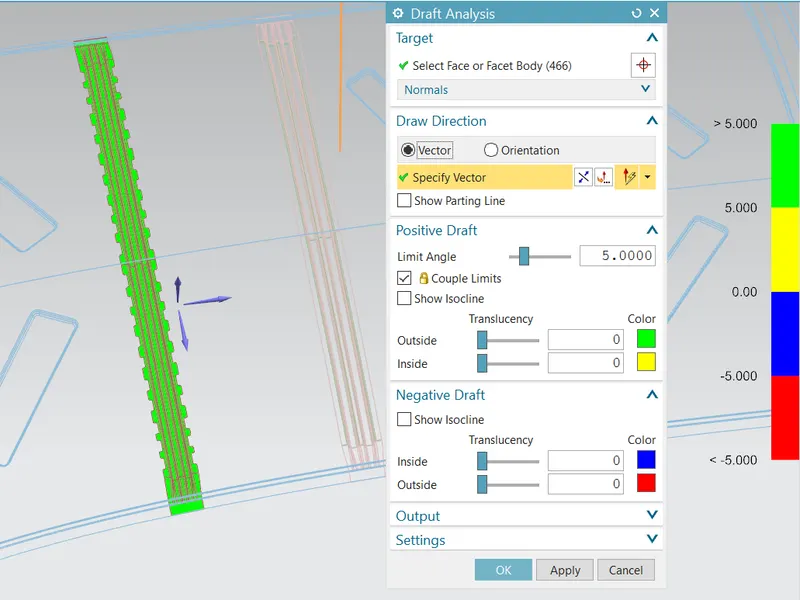
Draft analysis for bow roof 2:
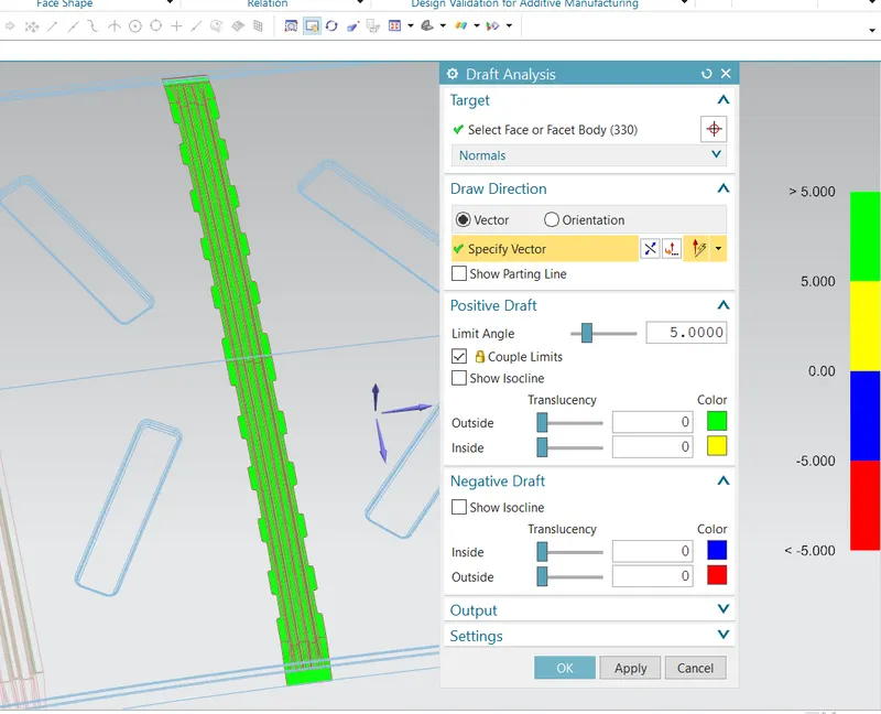
Draft analysis command enables you to detect whether the part yo creted will be easily removed while manufacturing from the die. minimum draft anggle of 7 degree is considered for the analysis, green color infers on the tooling direction has the positive draft angle thet is greter than 5 degree and passed the analysis.
Final conclusion :
The required roof asembly is designed with sufficient reinforcemnts and ditch area of the roof were designed and deweloped from the given styling surface and given master section. the curvature study was done after the calculation of the heat distortion and snow load condition with roof position creteria met all the reimforcement. the values are within limit. so they can be manufactured. manufacturability is checked by using the draft analysis. draft analysis for all the part is done. all the parts are manufacturable. draft angle is above 7 degree for all the parts. So all the analyis are done successfully.
So for heat distortion creteria all the values are below the 2.7 i.e ( 1.610, 2.2150, 1.5524, 1.62041 are less than 2.7 ) so these bow roof positions are safe to be used. All bow roof passed the heat distortion creteria.
All the Qr values are above the 3.1 so all the roof are safe to position. i,e the Qr values 18.61, 23.94, 6.44 are above the 3.1 as shown in table.
Suggestion : acoording second condition ( 250 ≤ s ≤ 380 ). the Distance front Front Roof centre to Roof BOW1 shound be reduced so s value come within range of 250 ≤ s ≤ 380[mm]. in my case the s values are above 300mm ie 486.93, 408.37, 538.14 mm. these s values should be made witin range by reducing L1 and L2 values of respective roofs span.