Roof Design
Roof Introduction:
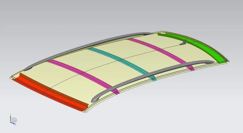
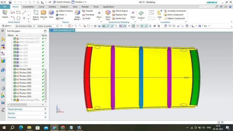
Given Car Roof stlying design develop a BIW Roof of a car with Front Roof Rail, Bow Roof Rail, Center Roof Rail, and Rear Roof Rail by following the engineering standards. The roof must be subjected to Draft Analysis for verifying whether it satisfies the manufacturing requirements. Curvature Study and Section Modulus Study needs to be carried out for the designed roof.
An automobile roof or car top is the portion of an automobile that sits above the passenger compartment, protecting the vehicle occupants from sun, wind, rain, and other external elements.
It also acts as a cross member between body sides of the car body and provides provisions for front windshields, backdoor. Roof assembly also one among the parts which provide safety for rollover accidents.
REINFORCEMENTS:
1. Ditch Area:
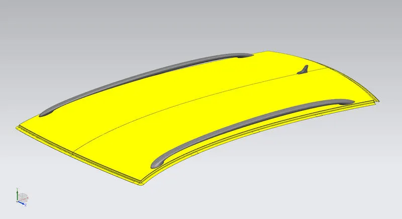
The Ditch Area of the Roof was designed by taking the considerations provided by the styling team. The ditch area was designed to have only 3 degree of maximum draft angle and 0.75mm thickness. The ditch area is the extended portion of the main roof concealed by other BIW panels. The rails of the roof were attached by using Spot welds and Mastic Sealants. Visibility Criteria, Head Room Clearance, windshield clearance and back door clearance was also taken into the design consideration of the Roof.
2. Front Roof Rail:
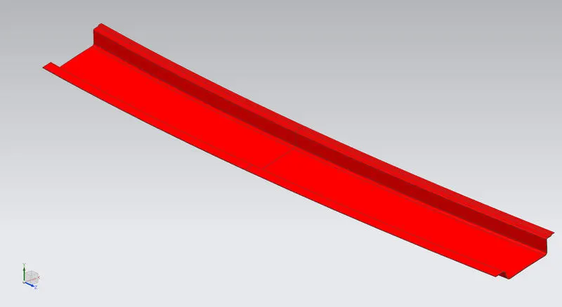
The front roof rail is located on the front of the roof where the wind shield joins with the roof. The visibility criteria and the head room clearance of the passenger are taken into consideration for the bottom flange. One end of the rail is joined using spot welding while the other end is joined with the roof using mastic sealants for increased strength.
3. Bow Roof:
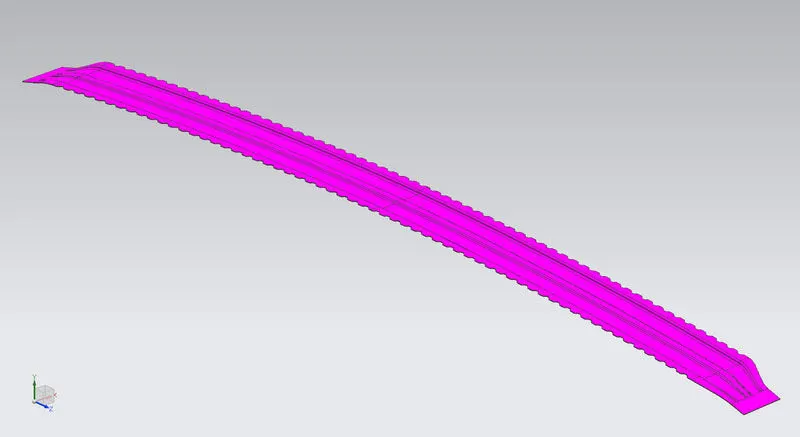
Bow roof is an additional siffening member for the roof to increase the strength and so that it can satisfy the norms. Both the ends are joined together using mastic sealants to increase strength and also this would not affect the styling of the roof.
4. Reinforcement Center:
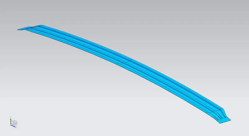
Centre Roof rail or the reinforcement centre is located at the centre of the roof. The cross section of this is more since it needs to provide more strength to the roof. Here both are ends are joined together using mastic sealants.
5. Rear Roof Rail:
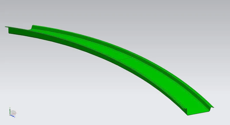
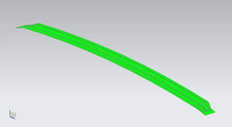
This roof rail joins with the back door and the roof. Inputs from the backdoor are taken into consideration for designing this roof rail. Here one end is joined using spot welding while the other end is joined using mastic sealants.
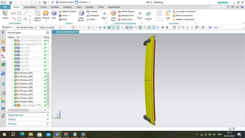
Roof Assembly
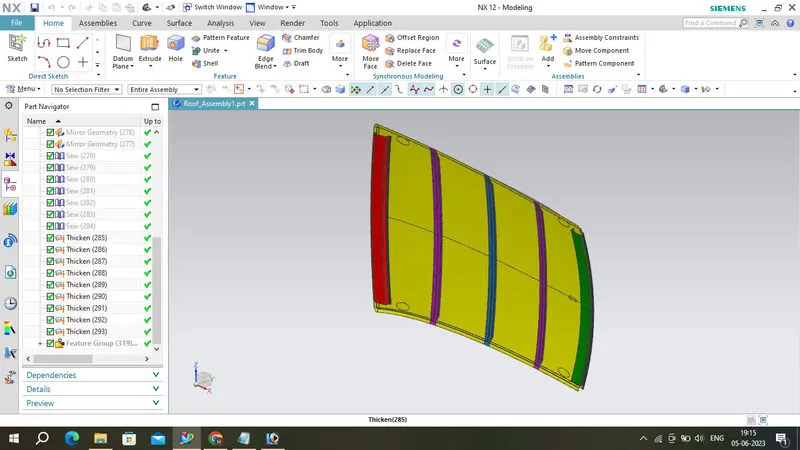
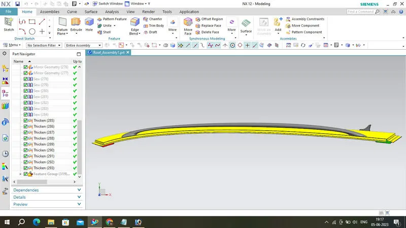
3D Part Views
ANALYSIS:
Heat Distortion Criteria:
Heat distortion temperature is the temperature at which the metal softens and deforms under a specific load. This study is done to check the ability of the roof to withstand high temperature with respect to the positioning of the reinforcements which contribute to increased strength.
Formula:
W=(1.73×10⁻³×L)+(1.85×10⁻⁸×R2t)+(1.10×10⁻³×l−2.68)
Condition:
where,
L = Roof Length in X-Direction in mm
R = Roof Curvature
R=2×Rx×Ry/Rx+Ry
Rx = X Curvature
Ry = y Curvature
t = Roof Thickness in mm
l = Bow Roof Span in mm
Snow Load Prediction:
Snow Load Prediction is a type of study done to check the ability of roof whether it can withstand to different temperatures like cold weathers, and also bear the atmosphere where the snow falls and rebound to its original position when a load of snow load is removed.
Formula:
Qr=Iy×t2α/×s×(Rx+Ry2)2×10−8
Condition: Qr=≥3.1
where,
s=Distance for which Roof BOW bears divided load in mm
s=L1/2+L2/2
α= My×Lx2×10−12,My=Y(Ly−Y)
Lx= Distance between the Left and Right end of the roof on the Roof BOW in mm
Ly= Distance between the front and rear roof Rails on the Vehicle along with OY in mm
Y= Distance front Front Roof Rail to Roof BOW in mm
Iy= Geometrical moment of inertia of Roof BOW (Y cross-section ) in mm4
t= Roof Thickeness in mm
Rx= Lateral Direction curvature radius of the Roof panel Y cross-section on Roof BOW in mm
Ry= Longitudinal Direction curvature radius of the Roof panel X cross-section on Roof BOW in mm
From the above results, these values for the snow load values it does not satisfy the condition.
To satisfy this condition we make the roof stronger we create embosses on the roof to strengthen the roof and increase the thickness of Bow.
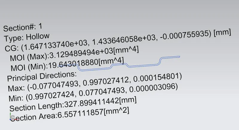
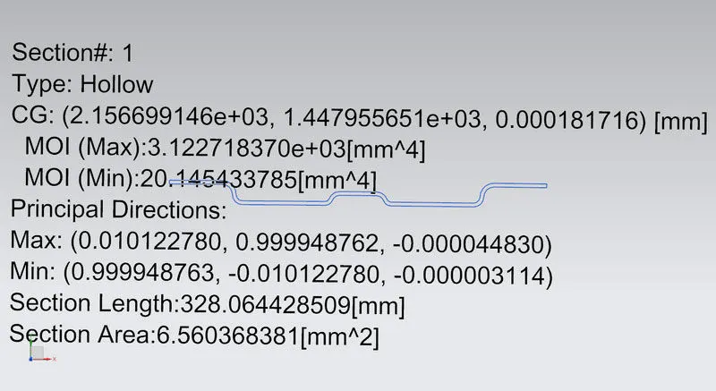
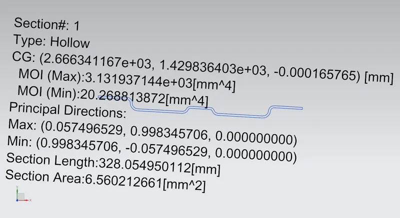
Section Modulus:
Bow Roof 1:
Reinforcement Center:
Bow Roof 2:
Draft Analysis:
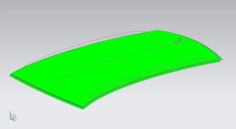
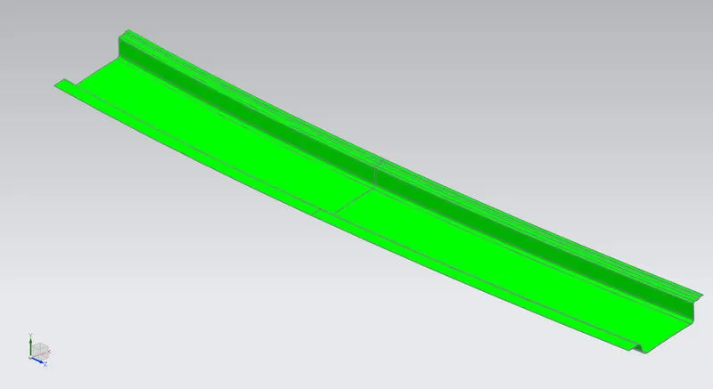
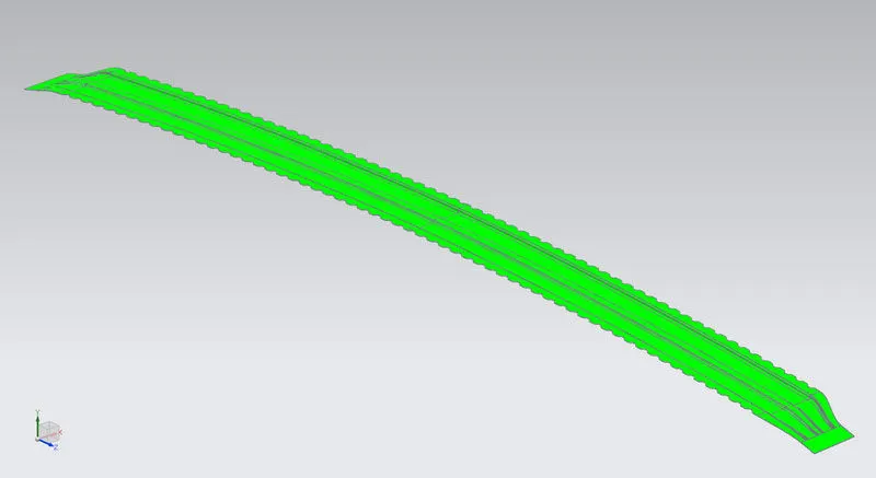
While designing a component a design engineer must make sure that the component can produced by any means of manufacturing methods with least amount of time, material, manpower and power. So that we can reduce the overall cost of car.
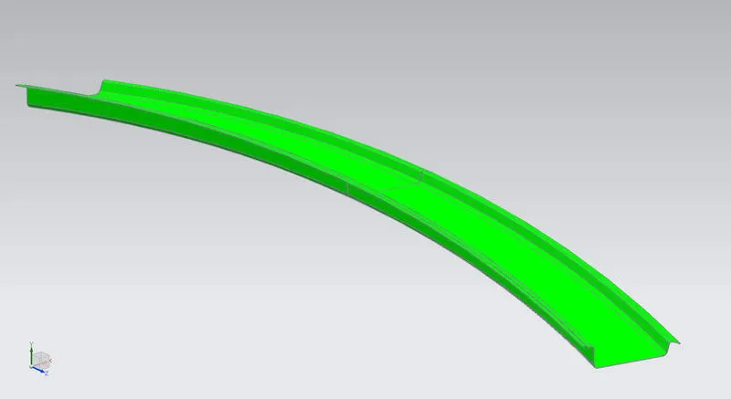
In NX draft analysis can be done after modelling so that we can verify whether the product is manufactured by pressing or not. One side of the surface is highlighted by green and other side by Red colour means that the model can be manufactured. Result of the draft analysis is shown in the figure below.
Ditch Area:
Front Roof Rail:
Bow Roof:
Reinforcement Center:
Rear Roof Rail:
CONCLUSION:
Thus the required Ditch Area, Bows and Reinforcements for the Roof were designed and developed from the given styling.
Calculations for the Heat Distortion criteria and Snow load predictions were also performed.
The BIW roof of a car was designed and achieved. For a better result applying Thickness in Bows and create Embosses over the Roof.