Roof Design
ROOF DESIGN
The roof of a car or any other vehicle serves as the uppermost part that provides protection to passengers or goods from various weather conditions. It acts as a shield, safeguarding occupants from rain, snow, sunlight, and other external elements. Moreover, the roof plays a crucial role in ensuring passenger safety during accidents, rollovers, or instances where heavy objects may impact the vehicle's top. It is designed to withstand external forces and provide structural integrity, reducing the risk of injuries to passengers inside the vehicle. The roof serves as a vital component in the overall safety and protection of the vehicle and its occupants.
OBJECTIVE:
- Perform the calculations for the Heat Distortion and Snow Load criteria by using the formulaes to determine whether the bow roofs are at the correct positions are not.
- Finding Moment of Inertia and Section modulus for Bow roofs.
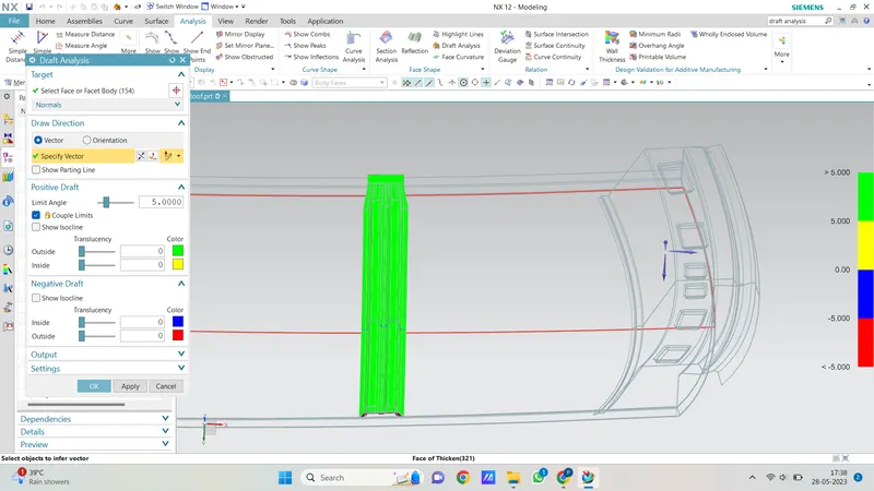
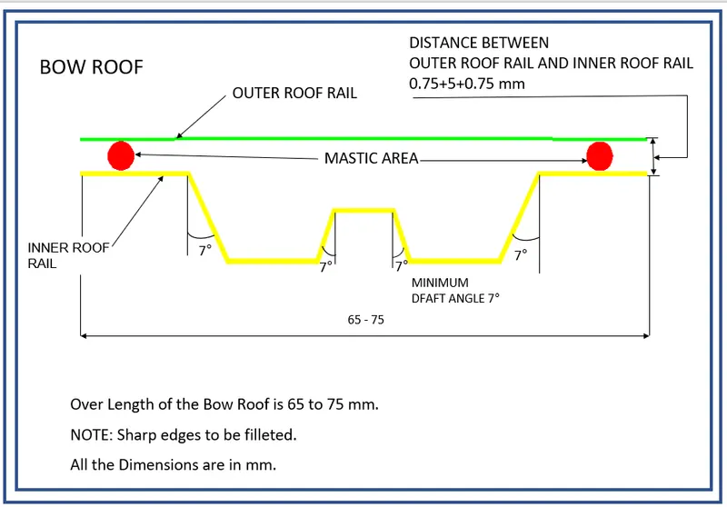
- Perform the Draft analysis for the reinforcements which we created.
INTRODUCTION:
An automobile roof or car top refers to the section of a vehicle that sits above the passenger compartment, offering protection to the occupants against various weather conditions such as sun, wind, rain, and more.
From an external perspective, the roof is simply the uppermost portion that covers the interior cabin. However, in terms of design, certain considerations must be taken into account. One of these considerations involves creating multiple roof rails to provide adequate strength and support to withstand loads.
Bow roofs are designed to be in a flat portion of the roof and are typically kept as straight objects to simplify the manufacturing process. These roof rails contribute to the structural integrity of the vehicle's roof.
Front and rear roof rails are fixed to the ditch area using spot weld operations. This method ensures a secure attachment between the roof rails and the vehicle structure. However, for the bow roofs and the center bow roof, a different approach is employed. These components are fixed to the roof using mastic sealants. This method helps prevent any damage to the aesthetic surface of the vehicle, ensuring a clean and visually appealing appearance.
In summary, the design of an automobile roof involves creating roof rails for strength and load-bearing purposes, using bow roofs in flat portions of the roof, and employing spot weld operations and mastic sealants for secure and damage-free attachments.
DESIGN CONSIDERATION-
-
Visibility criteria
-
Head clearance
-
Curvature study
-
Hear distortion and snow load criteria
-
Draft analysis.
Reinforcements for the roof play a crucial role in enhancing its strength and structural integrity. The following reinforcements are commonly used to provide support to the roof:
-
Front roof rail:
-
Rear roof rail:
-
Center roof rail:
-
Bow roofs:
These reinforcements work together to enhance the structural integrity of the roof, ensuring it can withstand external forces and provide safety to the vehicle occupants. The specific joining processes used may vary depending on the vehicle design and manufacturing requirements.
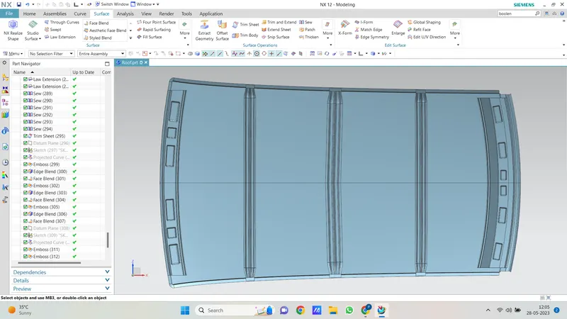
Front Roof Rail:
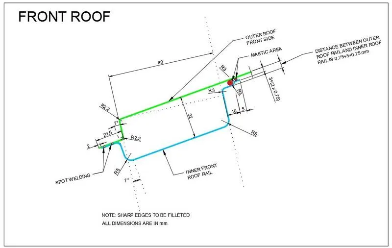
The front roof rail serves as a critical component in the overall structure of the roof. It is specifically joined to the A pillar of the car, providing support and reinforcement. The joining process typically employed for the front roof rail is spot welding, ensuring a secure connection.
During the design phase, embosses can be incorporated into the front roof rail to enhance its strength and load-bearing capacity. These embosses are created based on the specifications provided in the master section, ensuring proper alignment and structural integrity.
To further refine the design, fillets are added to the sharp edges of the front roof rail. Fillets help to smooth out transitions and reduce stress concentration, improving the overall durability and longevity of the component.
Finally, the front roof rail is thickened to achieve the desired thickness and strength. This ensures that the rail can effectively withstand external forces and contribute to the overall structural stability of the roof.
By following these design and manufacturing processes, the front roof rail is optimized for its intended purpose, providing the necessary support and reinforcement to the roof structure of the vehicle.
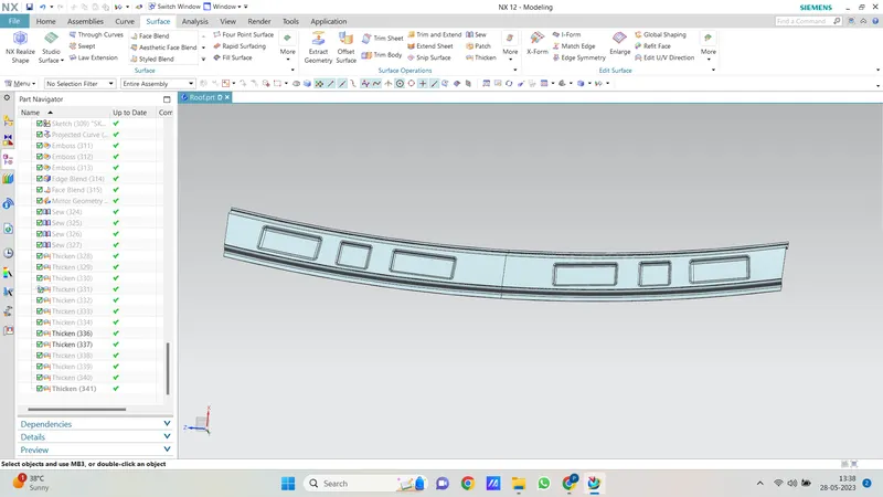
Rear Roof Rail:
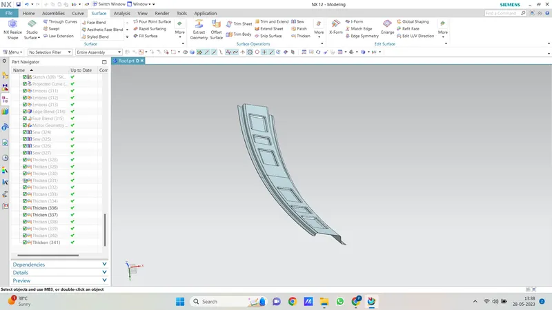
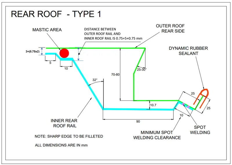
The rear roof rail is an essential component that connects the back door and the C pillar of the car. During the design process, the master section serves as a reference to ensure proper alignment and dimensions are followed.
Once the design based on the master section is established, the next step is to provide fillets to the sharp edges of the rear roof rail. Fillets are added to smoothen the transitions and minimize stress concentrations, contributing to improved structural integrity and overall durability.
After the fillets are applied, the rear roof rail is thickened to achieve the desired thickness. This ensures that the rail can effectively provide support and reinforcement to the roof structure.
By incorporating fillets and adjusting the thickness of the rear roof rail, the design is optimized for strength and functionality. The rear roof rail plays a crucial role in maintaining the structural integrity of the roof and ensuring passenger safety.
It's important to note that specific joining processes may be employed to securely attach the rear roof rail to the back door and C pillar, depending on the vehicle design and manufacturing requirements.
Central Roof Rail:
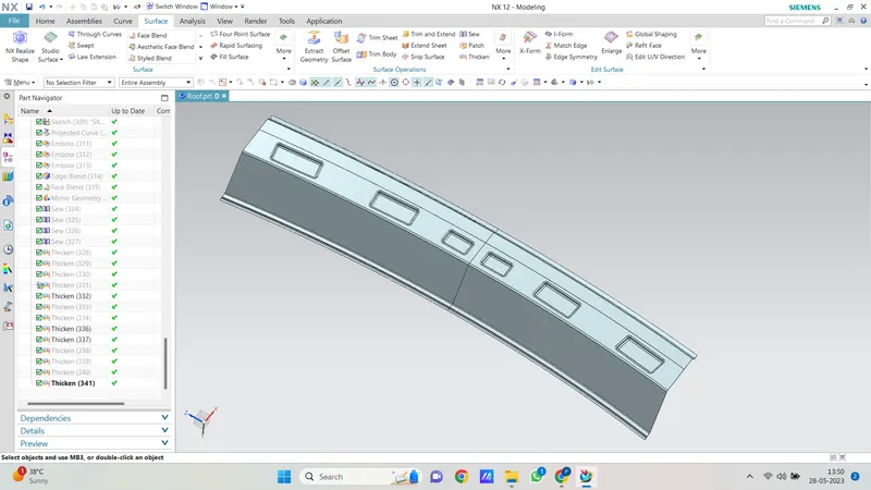
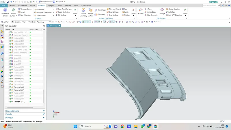
The central roof rail is positioned at the center of the roof and is typically connected to the B-pillar of the car. Unlike other joining processes, the central roof rail is attached to the roof using mastic sealants.
Mastic sealants are elastic compounds that provide a strong and secure bond between the roof rail and the roof surface. These sealants help to prevent any potential damage to the aesthetic surface of the vehicle and maintain a clean appearance.
During the installation process, the mastic sealants are applied between the central roof rail and the roof, ensuring a tight seal and a reliable connection. The sealants also contribute to reducing vibrations and enhancing the overall stability of the roof rail.
BOW ROOFS:
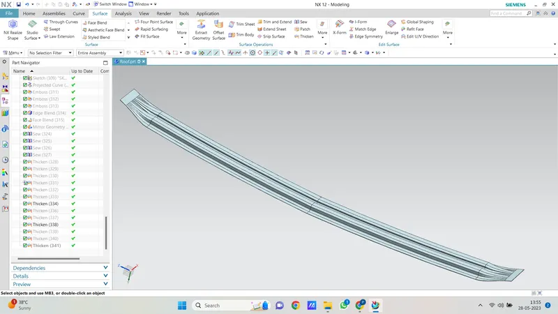
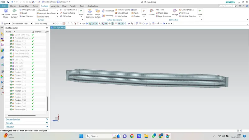
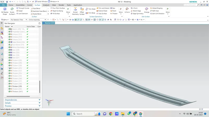
The bow roofs are provided to improve the torsional stiffness and load-bearing capacity of the roof structure.To increase the strenth on the flatter region or surface we are providing the bow roofs. The number of bow roof present depends on the overall size of the roof. In this project two bow roofs are sufficient before and after the centre roof rail.
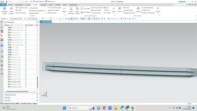
Roof assembly:
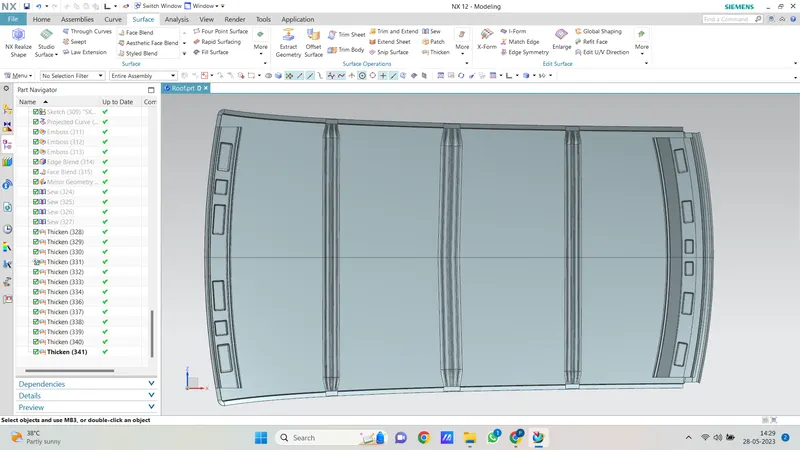
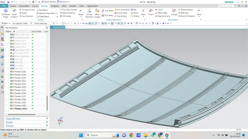
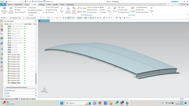
Calculation-
CURVATURE STUDY ON ROOF:
- Heat Distortion study
- Snow Load study
Heat Distortion Curvature Study-
This study is used to find out and predict the heat distortion temperature at where the material starts to soften when exposed to a fixed load. So in order to avoid bending or damage of the roof based on this calculation we will decide the position on the roof bows on the roof.
Formula:-
W = [1.73 x 10^(-3) x L] + [1.85 x 10^(-8) x (R^2)/t] + [ 1.10x10^(-3) x l] - 2.68
Where,
L = Roof Length in X-Direction[mm](Roof dimension in 0-Y)
R = Roof curvature
R = 2(Rx*Ry)/(Rx+Ry)
Rx = X curvature
Ry = Y curvature
t = Roof plate thickness [mm]
l = Bow Roof Span [mm]
Judgment Condition
OK< 2.7
| BOWS | Rx | Ry | R | L | l | t | R^2/t | W | OK/NG |
| FRR-BR1 | 706.600 | 2400.141 | 1091.780 | 2029.1364 | 374.7866 | 0.75 | 1.5893*10^6 | 1.27 | OK |
| BR1-CRR | 4965.102 | 6219.295 | 5521.877 | 2029.1364 | 428.4607 | 0.75 | 40.6548*10^6 | 2.05 | OK |
| CRR-BR2 | 3993.131 | 10496.388 | 5785.347 | 2029.1364 | 425.2588 | 0.75 | 44.6269*10^6 | 2.12 | OK |
| BF2-RRR | 3241.511 | 14837.813 | 5320.656 | 2029.1364 | 357.1055 | 0.75 | 37.7458*10^6 | 1.92 | OK |
From the above table it is concluded that all values of w are less than 2.7 and also not greater than 3.1(i.e OK< w > 3.1 ) so thus infers that current positioning of bow roofs are good in state for heat distortion as per design.
SNOW LOAD Study on the Roof:
Qr = [Iy x t2] / [α x s x [(Rx + Ry)/2]2 x 10-8]
Note: The Qr value given over here is correct. There was a typo error in the formula given in the video.
Where,
α = My x Lx2 x 10-12 , My = Y(Ly-Y)
t = Roof plate thickness [mm]
Ly = Distance between the front and rear roof Rails on the Vehicle along with 0Y[mm]
Length of Roof panel with the center point between Roof rail Front /Rear as the front and rear reference point.
Lx = Distance between the Left and Right end of the roof on the Roof BOW [mm]
The width of the roof panel is exposed on the surface.
Y = Distance front Front Roof Rail to Roof BOW[mm]
s = Distance for which Roof BOW bears divided load [mm]
s = L1/2 + L2/2
Iy = Geometrical moment of inertia of Roof BOW (Y cross-section )[mm4]
Rx = Lateral direction curvature radius of roof panel Y cross-section on Roof BOW [mm]
Roof panel curvature Radius of the Length Lx in Front view
Ry = Longitudinal Direction curvature radius of the Roof panel X cross-section on Roof BOW [mm]
Roof panel X curvature radius of length s in Side view
Judgment condition
Qr ≥ 3.1
| BOWS | Iy(MM^4) | t | alpha | Lx | Ly | Y | s | Rx | Ry | Qr | RESULT(Qr>3.1) |
| FRR-BR1 | 1572.7292 | 0.75 | 0.9118 | 1141.0173 | 1964.6911 | 467.9052 | 489.1469 | 4623.354 | 2471.055 | 15.764 | OK |
| BR1-CRR | 1998.0434 | 0.75 | 1.13952 | 1086.6808 | 1964.6911 | 978.2938 | 508.7953 | 3764.912 | 6128.055 | 7.921 | OK |
| CRR-BR2 | 1646.2761 | 0.75 | 0.7978 | 1058.6751 | 1964.6911 | 1485.4959 | 493.1986 | 3184.563 | 10981.320 | 4.691 | OK |
| BF2-RRR | - | 0.75 | - | 1043.3766 | 1964.6911 | 1964.6911 | - | 3942.159 | 16749.422 | - | - |
From the above table it is concluded that all values of Qr are greater than 3.1, so thus infers that current positioning of bow roofs are good in state for snow load as per design.
Draft analysis:-
front bow:
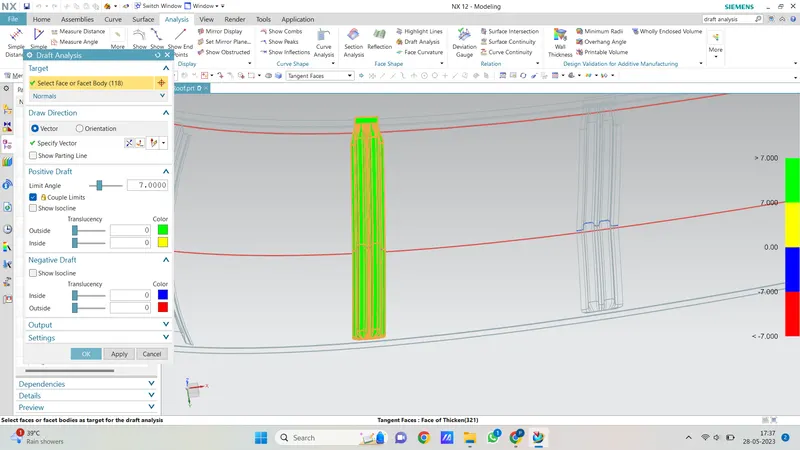
Center roof bow
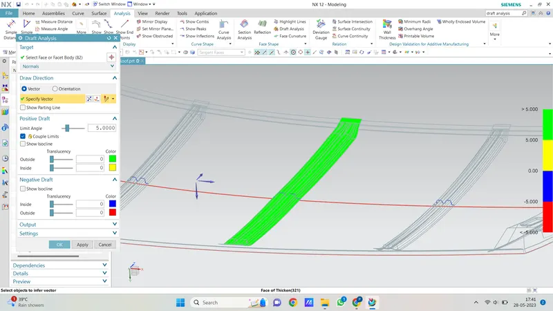
Rear bow:-