Roof Design
1.1 Aim:
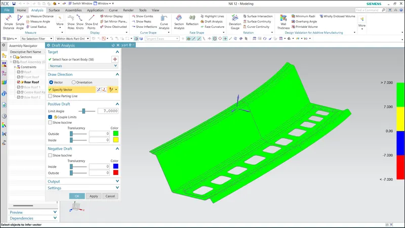
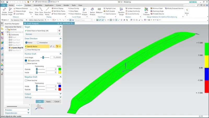
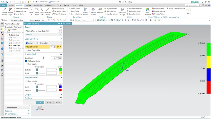
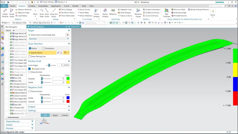
To design a car roof, it is essential to incorporate various reinforcements, including the front roof rail, rear roof rail, bow roof rail, and center roof rail. Additionally, the roof assembly must have a minimum draft angle of 7 degrees and a thickness of 0.75.
2.1 Designing Of Roof:
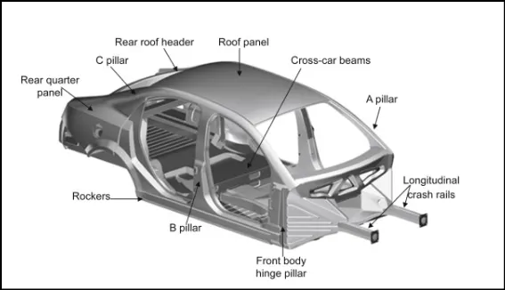
The car roof serves as the top portion of the vehicle, shielding passengers from harsh environmental conditions such as sun, wind, and rain. It is aerodynamically shaped to minimize the impact of wind when the car is in motion. The roof is supported by A, B, and C pillars.
Underneath the roof, there are additional structures that provide strength and stability. These reinforcement structures are installed on the flat surface of the roof, enhancing its overall strength.
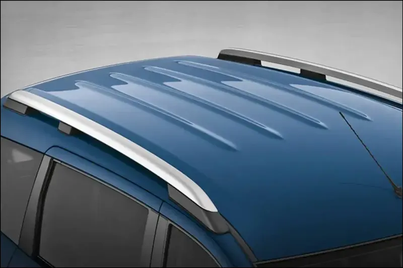
The design of the roof starts with the Class A Surface or Styling surface, taking into account important factors such as front and rear visibility criteria, as well as headroom clearance. While the roof is not primarily intended as a load-carrying member, it must be designed to withstand unforeseen situations without dents or permanent deformation, ensuring its strength and durability.
2.1.1 Reinforcements for roof
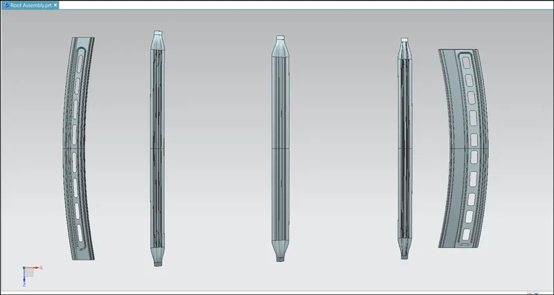
The roofs are reinforced with five structures which acts as support members.They are
1.Front roof rail
2.Rear roof rail
3.Center roof rail or Center bow roof rail
4.Front bow roof rail
5.Rear bow roof rail.
2.1.3 Roof Crash Test:
Conducting crash tests on vehicle roofs is crucial for ensuring safety. In the event of an accident, particularly a rollover, the roof can experience deformation that poses a risk of injury to passengers, including the head and neck. It is essential to prioritize passenger safety in every vehicle design.
Efficiency and fuel mileage can be improved by reducing the weight of the vehicle, achieved by using lower gauge thick sheets in the Body in White (BIW). However, this reduction in weight can result in quicker fractures and damages during accidents, potentially leading to severe injuries or fatalities. Therefore, conducting crash tests, including the Roll-Over test, is imperative.
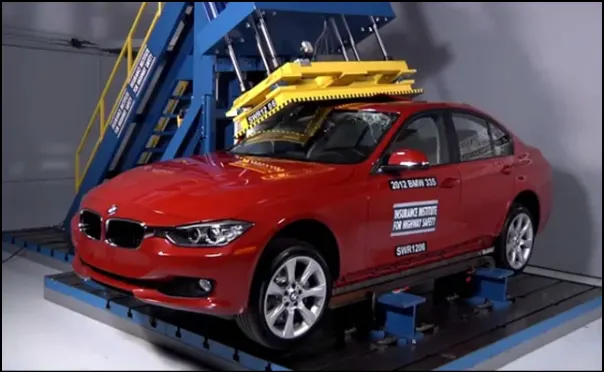
International standards and governmental requirements specify the need for crash tests in several countries. These standards are established by organizations such as the Institute of Highway Safety. They provide regulations and ratings to evaluate how well a car responds to the original condition and measure the depth of protrusion after collision.
The Roll-Over test is particularly significant for assessing the strength and safety of a vehicle roof, considering the potential risks passengers may face during a rollover accident.
2.1.4 Condition for Crash Test:
During the Roll-Over test, specific procedures are followed to assess the strength and performance of the vehicle's roof. The test focuses on the Body in White (BIW) or outer body of the car. The following steps are typically involved:
- Close and lock all doors of the vehicle.
- Close the windows.
- Place the car on a horizontal surface.
- Apply a load of 22,040 N (approximately 2,250 kgf) on the roof from the outside.
- The load is applied for approximately 120 seconds.
- The load is applied at a 5° angle from the front and a 25° angle from the side of the car.
- The load is applied over a length of 1800 mm and a width of 750 mm on the roof.
- The speed of load application is approximately 13 mm/sec.
The strength of the roof structure is evaluated based on various criteria. One criterion specifies that the maximum displacement of the roof structure should be less than 127 mm (5 in.) when the induced load is 1.5 times the vehicle weight.
The displacement of the load application device should be 127 mm or less when a load of 1.5 times the unloaded vehicle weight (22,240 N) is applied.
The test can be conducted on either the front left or front right side of the roof structure but not on both sides in a single test.
The force applied during the test should be downward and perpendicular to the lower surface of a rigid plate. The force should move in a straight line without rotation. The duration of the test should not exceed 120 seconds.
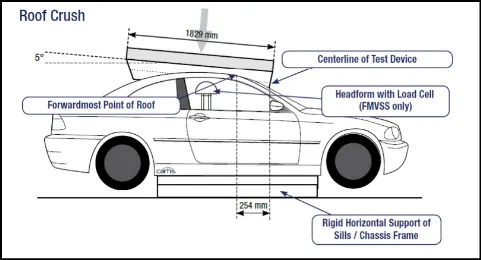
The pitch of the longitudinal axis of the plate should be forward at a 5° angle as viewed from the side of the passenger car. The roll of the lateral axis of the plate should form a 25° outboard angle with a horizontal surface as viewed from the front of the passenger car.
2.1.5 Types Of Automotive Roofs:
There are several types of automobile roofs, each offering unique features and characteristics:
-
Convertible: A convertible, cabriolet, or spyder is a passenger car that can be driven with or without a roof in place. The roof can be folded or retracted, providing an open-air driving experience.

-
Hardtop: A hardtop has a rigid structure made of metal, typically constructed as a fixed roof. It can also be detachable for separate storage or retractable within the vehicle itself.
-
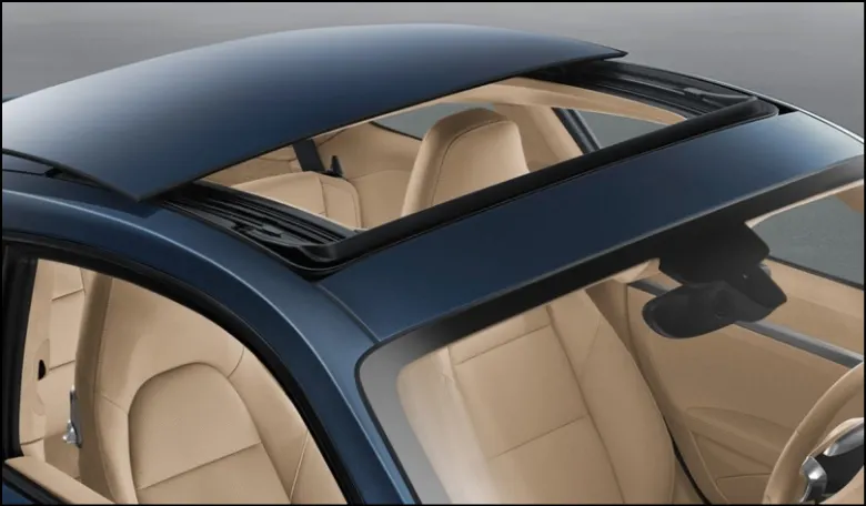
Sunroof: A sunroof is a movable panel that can be operated to uncover a window in the automobile roof. It allows light and fresh air to enter the passenger compartment while providing some protection from the elements.
-
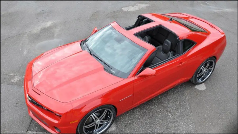
T-top: A T-top roof has removable panels on each side of a rigid bar that runs from the center of one structural bar between the pillars to the center of the next structural bar. The panels are typically made of safety glass.
-
Targa top: A Targa top is a semi-convertible car body style with a removable roof section and a full-width roll bar behind the seats. It offers a balance between open-air driving and structural rigidity.
-
Vinyl roof: A vinyl roof refers to a vinyl covering for the top of an automobile. Initially designed to give the appearance of a convertible to models with a fixed roof, it later became a styling statement on its own.
These different roof types provide options for varying levels of openness, convenience, and design aesthetics in automotive vehicles.
2.1.6 Design considerations:
The draft angle should exceed 7 degrees to meet the desired specifications. When considering headroom clearance, it is important to ensure that the height of the bow roof rails, which are added to provide support to the roof surface, does not exceed 20 mm. The optimal number and placement of bow roof rails are determined through the utilization of empirical formulas such as the Bow load prediction formula and Snow load prediction formula. These formulas help in optimizing the design to ensure structural integrity and load-bearing capabilities.
3.1. Manufacturing Processes:
1. Seam Welding:
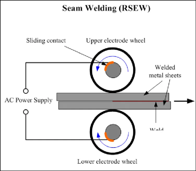
Seam welding is a type of resistance welding where two rollers are used to weld the workpiece, resulting in a leak-proof joint. It is commonly used for joining sheet metal components.
2. Spot Welding Operation:
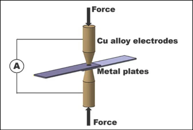
Spot welding is a type of resistance welding where a lap joint is created by applying pressure with a conducting electrode and creating a large potential difference between the metal objects being joined. The high resistance at the interface causes the material to melt and form a spot weld.
3. Hemming:
Hemming is a forming operation that involves folding or bending the edges of a sheet over another part to achieve a tight fit. It is used to connect parts together, improve appearance, and reinforce part edges.
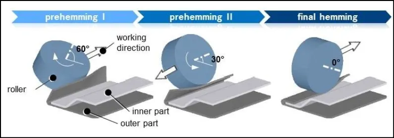
There are two types of hemming:
-
Conventional die hemming: This method is suitable for mass production, where a hemming tool is used to fold the entire flange in one shot.
-
Roll die hemming: In this method, the flange is gradually folded, resulting in a longer cycle time but easier tool handling and cost efficiency.
4.1 Roof Design Methodology:
The roof assembly consists of the following components, designed according to the provided master section and engineering guidelines
4.1.1 Front Roof Rail
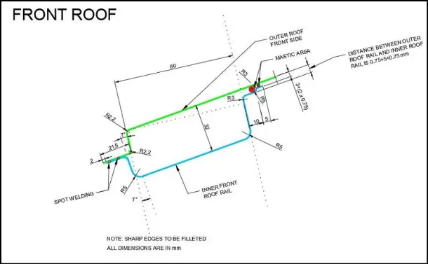
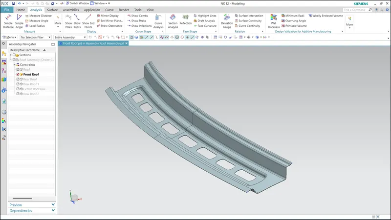
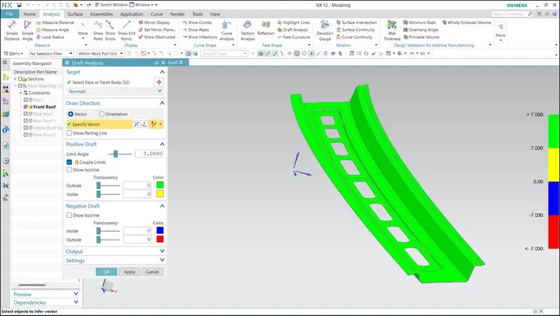
The front roof rail serves two purposes: providing strength to the front of the roof and acting as a connection point between the windshield glass roof panel and the headliner. Spot welds are applied at the windshield end of the rail, while the other end is joined with the roof using mastic sealant, which enhances strength.
Master Section:
Front Roof Rail:
Draft Analysis:
4.1.2 Rear Roof Rail
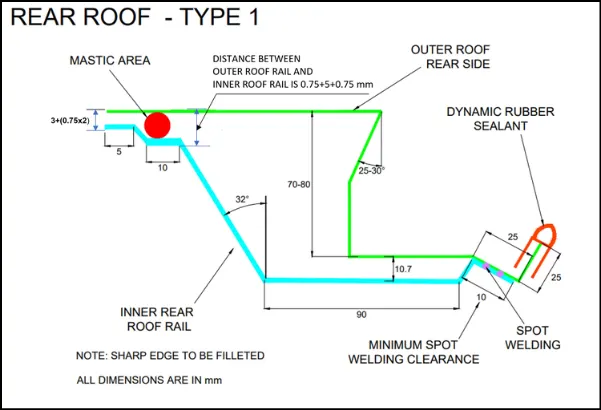
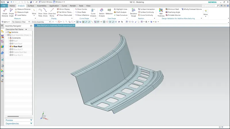
Similarly, the rear roof rail strengthens the roof and serves as a link between the back glass and the roof, connecting to the back door of the car. Spot welds are applied at the back door end of the rail, and the other end is joined with the roof using mastic sealant.
Master Section:
Rear Roof Rail:
Draft Analysis:
4.1.3 Center Roof Rail
The center roof rail, located in the middle of the roof, provides strength and stability. It is joined with the roof through mastic sealant.
Master Section:
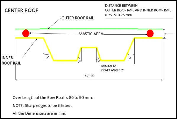
Center Roof Rail:
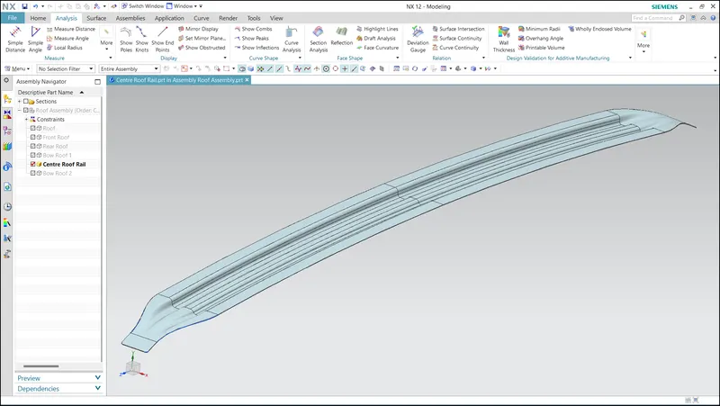
Draft Analysis:
Section Modulus of Center Roof Rail:
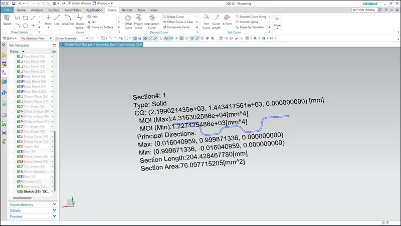
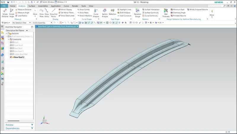
4.1.4 Bow Roof Rail:
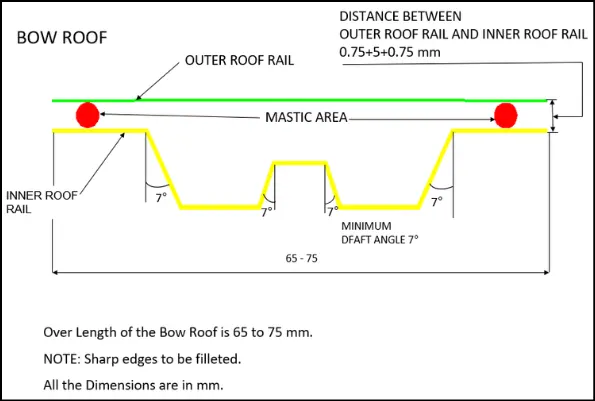
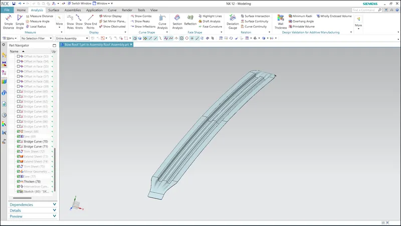
The bow roof is specifically designed to add support and strengthen the linear curvature area of the roof. These reinforcements are strategically placed to enhance structural integrity and ensure the roof can withstand unforeseen situations without deformation.
The ditch area is an extended portion of the main roof. The rails that support the roof are attached to the ditch area using spot welds, further enhancing structural integrity.
Master Section:
Bow Roof Rail 1:
Draft Analysis of Bow Roof 1:
Section Modulus of Bow Roof 1:
Bow Roof Rail 2
Draft Analysis of Bow Roof 2
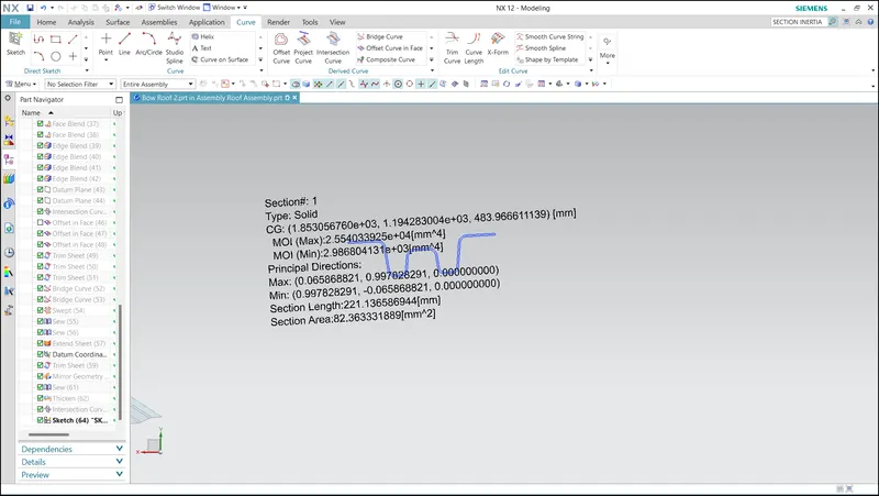
Section Modulus of Bow Roof 2
4.1.5 Hood Outer Panel:
The outer panel forms the external surface of the roof and provides aerodynamic shape while protecting passengers from environmental elements such as sun, wind, and rain.
Hood Outer Panel:
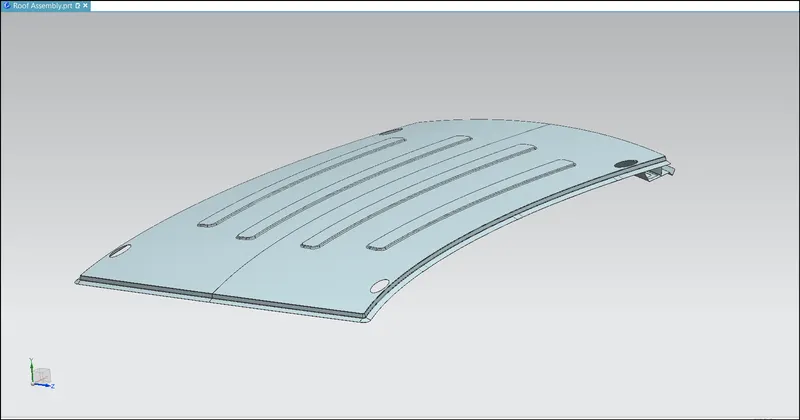
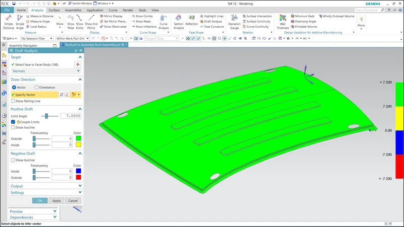
Draft Analysis:
5.1 Calculations:
As said before, here i have performed calculations to ensure the effectioness of the Bow Roof Rails
5.1.1 Heat Distortion Analysis:
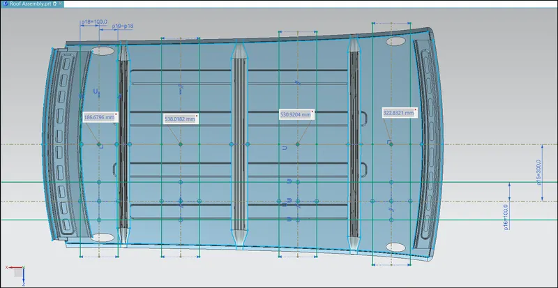
The procedure for determining the position of the bow roof to ensure the roof's strength and functionality under elevated temperatures is as follows:
-
Draw a horizontal line that passes through the 0-Y axis of the roof.
-
Offset 300 mm on both sides along the 0-Y axis.
-
Offset 100 mm above and below the offset line.
-
Draw a vertical line in the middle of the two offset components, offsetting 100 mm on both sides of this line.
-
Project the intersection point on the roof's outer panel.
-
Draw a 3-point arc and use the local radius command to determine the values of Rx and Ry, which are the radii of the bow roof.
By following this procedure, the bow roof can be positioned in the most affected location to ensure the roof retains its functionality and strength even at elevated temperatures.
Formula
W = [1.73 x 10^(-3) x L] + [1.85 x 10^(-8) x (R^2)/t] + [ 1.10x10^(-3) x l] - 2.68
Where,
L = Roof Length in X-Direction[mm](Roof dimension in 0-Y)
R = Roof curvature
R = 2(Rx*Ry)/(Rx+Ry)
Rx = X curvature
Ry = Y curvature
t = Roof plate thickness [mm]
l = Bow Roof Span [mm]
Calculation Sheet

Judgment Condition
OK< 2.7
From the above Calculation Sheet , its is concluded that the designed roof satisfies the heat distortion criteria.
5.1.2 Snow Load Analysis:
To ensure that the car roof can withstand the load caused by frequent snowfall and return to its original shape once the load is removed, the following procedure can be followed:
-
Draw a horizontal line along the 0-Y axis of the roof.
-
Offset 100 mm on both sides along the 0-Y axis.
-
Draw a vertical line in the middle of the midline of two consecutive roof components.
-
Project the intersection point on the roof's outer panel and create a 3-D Arc.
-
Calculate the radius of curvature (Rx and Ry) using the local radius analysis command.
By following this procedure, the car roof can be designed to have the necessary strength and flexibility to withstand the load from snowfall. The curvature of the roof, determined by the calculated radius values, allows it to deform under load and return to its original shape once the load is removed, ensuring its functionality and structural integrity.
Formula:
Qr = [Iy x t2] / [α x s x [(Rx + Ry)/2]2 x 10-8]
Note: The Qr value given over here is correct. There was a typo error in the formula given in the video.
Where,
α = My x Lx2 x 10-12 , My = Y(Ly-Y)
t = Roof plate thickness [mm]
Ly = Distance between the front and rear roof Rails on the Vehicle along with 0Y[mm]
Length of Roof panel with the center point between Roof rail Front /Rear as the front and rear reference point.
Lx = Distance between the Left and Right end of the roof on the Roof BOW [mm]
The width of the roof panel is exposed on the surface.
Y = Distance front Front Roof Rail to Roof BOW[mm]
s = Distance for which Roof BOW bears divided load [mm]
s = L1/2 + L2/2
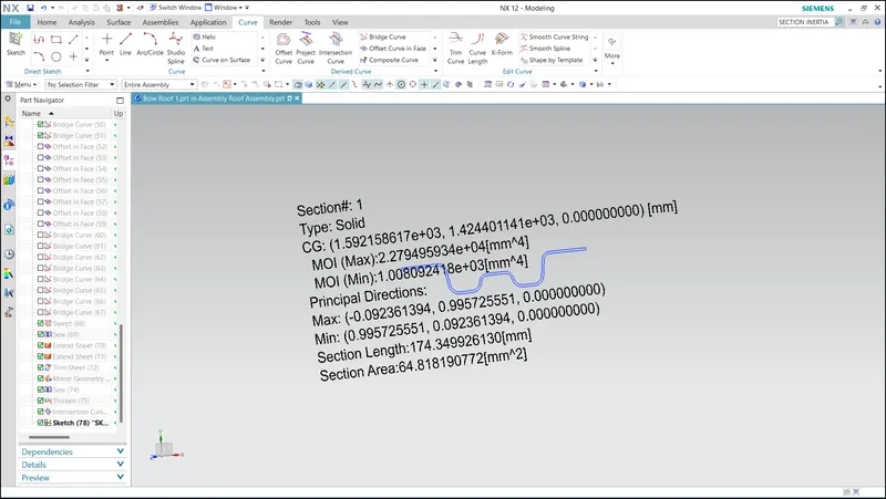
Iy = Geometrical moment of inertia of Roof BOW (Y cross-section )[mm4]
Rx = Lateral direction curvature radius of roof panel Y cross-section on Roof BOW [mm]
Roof panel curvature Radius of the Length Lx in Front view
Ry = Longitudinal Direction curvature radius of the Roof panel X cross-section on Roof BOW [mm]
Roof panel X curvature radius of length s in Side view
Calculation Sheet:

Judgment condition
Qr ≥ 3.1
From the above Calculation Sheet, its is concluded that the designed roof satisfies the Snow Load Criteria.
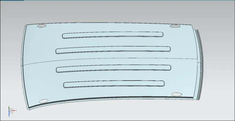
Also to provide more stiffness and aesthetic look to the Roof, Embosses were created and yet in this case it is just optional and for styling purpose only.
6.1 Conclusion:
The Roof Assembly was modeled in NX CAD, incorporating components such as the Roof Outer Panel, Front Roof Rail, Rear Roof Rail, Center Roof Rail, Bow Roof 1, and Bow Roof 2. The design of these components were based on the provided master section. The roof design was validated through tests for Heat Distortion and Snow Loading.
- The Heat Distortion test ensured that the roof can withstand elevated temperatures without warping or deforming.
- The Snow Loading test confirmed that the roof design and reinforcement rails can handle the weight of accumulated snow without compromising safety or causing damage.
The results of the validation tests showed that the roof design meets the required criteria.
Hood Assembly:
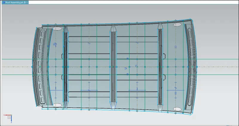
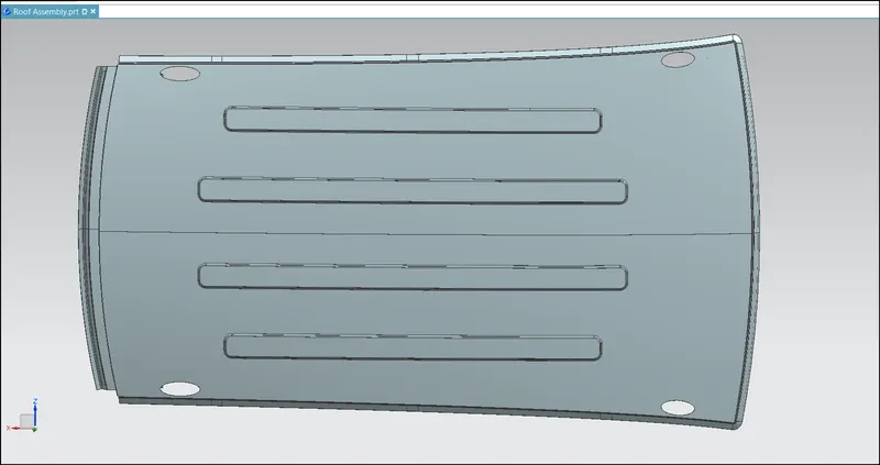
Top View:
Bottow View:
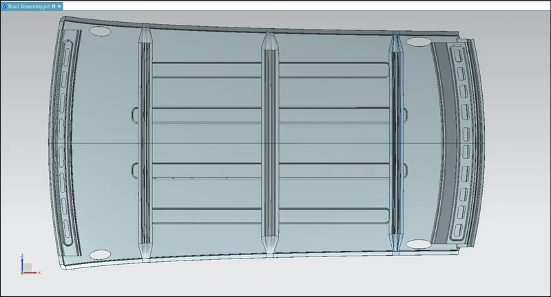
Reinforcements: