Roof Design
1. Title :- TO design and discuss about the car roof model with their components
2. Introduction :-
The roof is a part of the car body, it protects passenger from sunlight, wind, rain and other external elements. It is attached to the upper part of the car body. The roof looks like a single metal sheet from outside but it has 5 sub parts – outer panel, front roof rail, rear roof rail, bow roof and center roof. All plates are jointed by spot welding. The company adds reinforcement material between roof plane and rails or bow plate to increase the strength of the roof. To increase the strength of the roof, the company designer also uses bow roof plate multiple times.
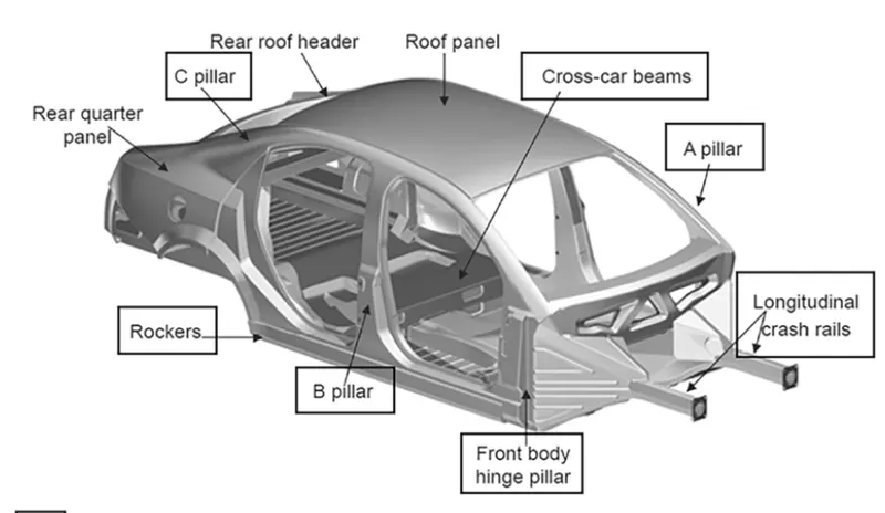
In this project we will discuss about the roof and its sub-parts, their design consideration. we will create a 3D model of the roof with the help of NX CAD software. Based on the given blueprints we will prepare the model of the front roof rail, rear roof rail, center roof and bow roof plate and we will ready whole design of roof. We have written about the manufacturing process of roof.
3. Objective :-
- To create 3d model of car roof and its sub-components with using of master drawing in NX-CAD software.
- We discuss about the design consideration and roll over test of roof .
- Calculate pedestrian formula(heat distortion criteria and snow criteria) for roof rails and bow roof and check their limitation.
- Discuss manufacturing process for the roof.
4. Roof
An automobile roof or car top is the portion of an automobile that sits above the passenger compartment, protecting the vehicle occupants from sun, wind, rain, and other external elements.
Design requirements for the roof
- Type of roof
- Roll over test regulation and requirement
- Identification methods to increase the strength of the roof
- Material Identification techniques joining techniques like mastic, welding
- Gap and flushness requirements
Roof and its parts
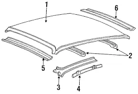
- Main Roof panel - (1)(outer roof panel )
- Front roof rail - (5)
- Rear roof rail - (6)
- Center roof
- Bow roof - (2)
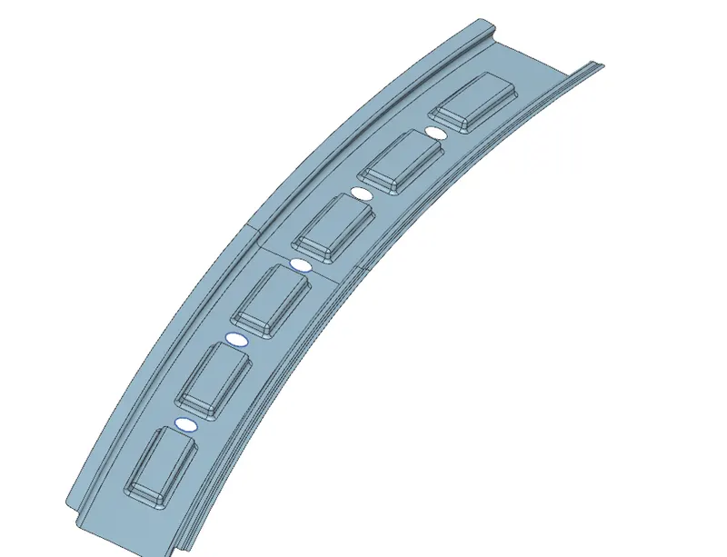
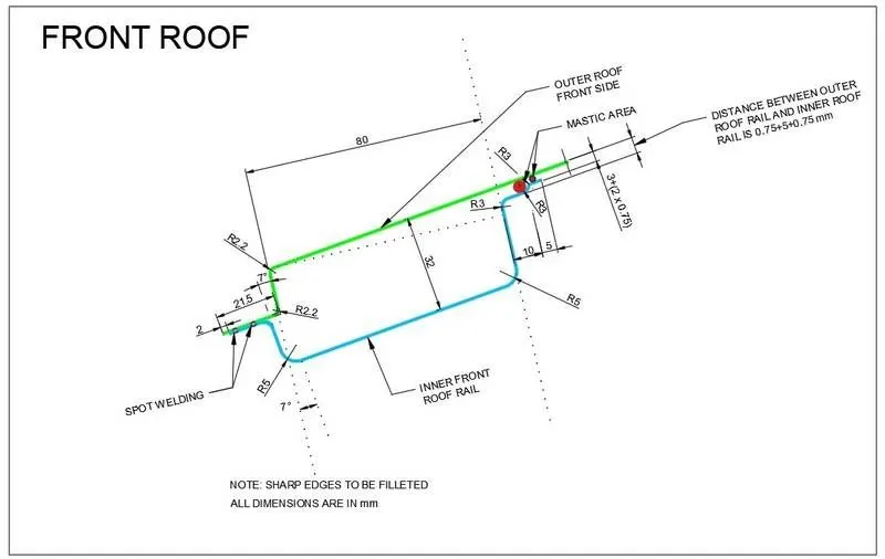
Front roof rail
Front rail is jointed by the spot welding on front side of the car roof. Front roof rail is increasing strength of roof and it is providing mounting point for the windsild glass. Company fill rainforcement material between outer panel and front roof rail which is providing strength. At the corner of the front rail we put the mastic silens.
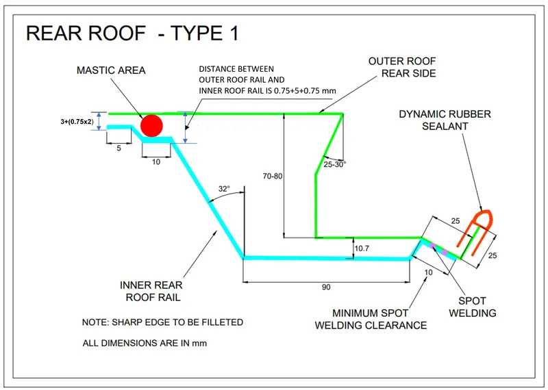
Rear roof rail
Rear roof rail is placed rear side of the car roof. their design structure give us to place rear backdoor. Rear Rail structure is providing smooth close and open condition for the back door. Top roof and rear roof is joining together by mean of spot welding and mastic sillens.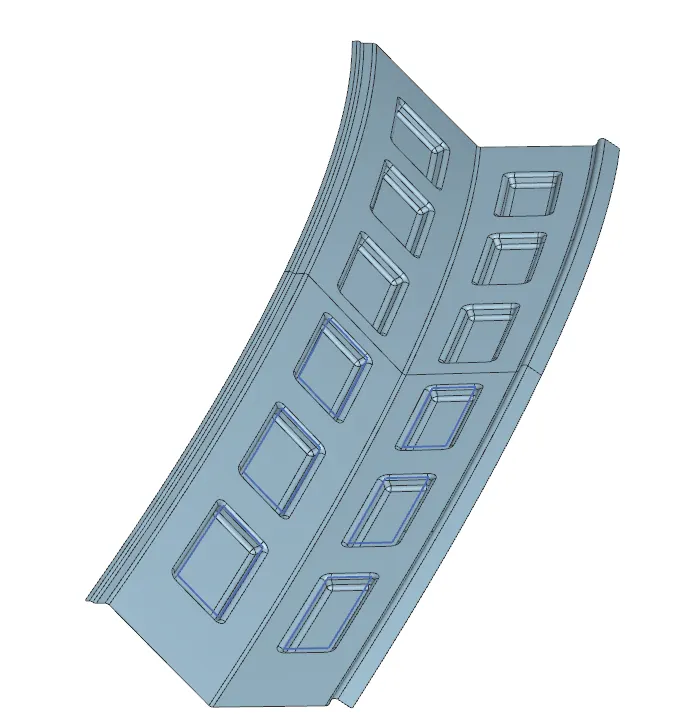
Center bow roof
Center bow roof has two type, one is for without sunroof model and second is for with sunroof. With sunroof model it includes two plate in bow roof without sunroof it contains only one plate. Bow roof plate are providing strength for the roof. Outer panel and center bow are joining by the mastic glue.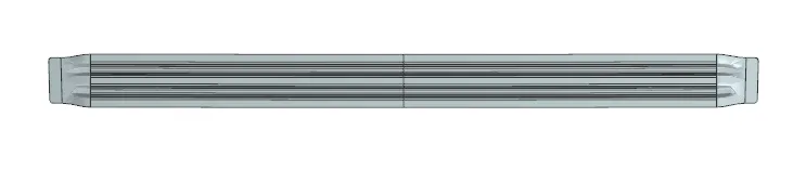
Bow roof
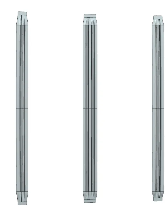
Bow are placed between front rail and center bow or rear rail and center bow. Bow plates are used as per requirement strength for roof. It is joined by using mastic sillens and spot welding.
Top roof plate
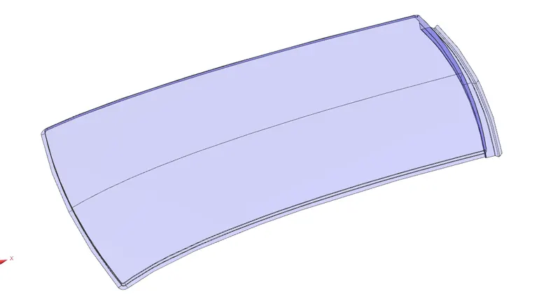
This plate is class A surface finish plate which is placed outside of the roof. Top roof plate and other sub components are joined by the mastic silens or spot welding.
Roof Crush test :-
Roof crush is the failure and displacement of an automobile roof into the passenger compartment during a rollover accident.
All vehicles roll over. Due to their higher center of gravity and narrow wheel base, sport utility vehicles roll over more than passenger cars.
In rollovers, the biggest risk of injury to passengers is from ejection. Seat belts alone do not protect passengers in rollovers for a number of reasons: buckles frequently unlatch or fail, slack is created in the restraint system that permits passengers to be literally pulled out of their seats by the forces in a rollover, or the passenger is still partially ejected out of the windows because the restraints do not keep passengers in their seats.
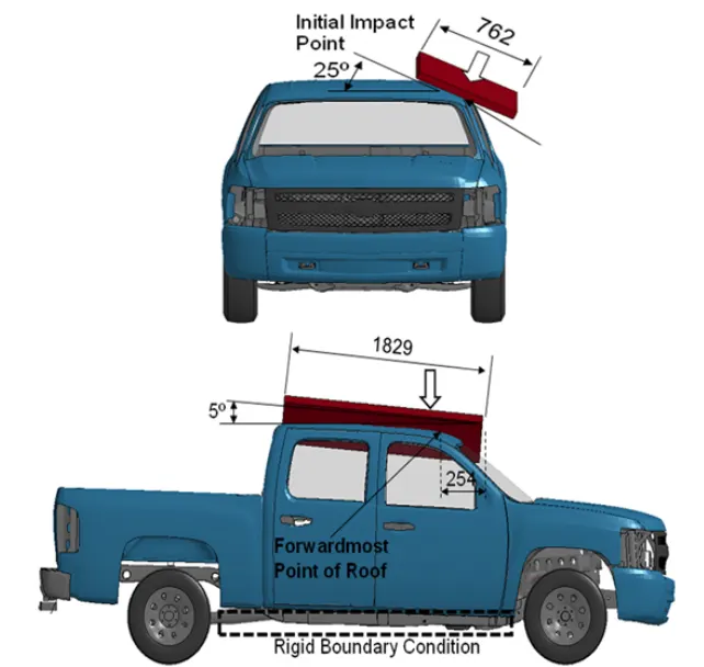
If the seat belt system does its job, there is still another risk in a rollover. The roof structures of many SUVs are so poorly reinforced that the roof literally crushes the passengers where they sit. For many years, automakers have argued that people are not injured by roof crush and there was no relationship between roof strength and risk of injury. Automakers have presented the incredible argument that people are injured when they "dive" into the roof during a rollover event before the roof crush."
Aim of the crush test :-
- When the car is overturned, we will check how much deformation is caused by the load on its roof.
- If deformation value is higher, the strength of the roof has to be increased.
Conditions for the roof crush test :-
This test have
- First condition:-
Close and lock all doors of car
Close all the windows
- Second condition
Fix the body or chassis frame on a test area
Method of applying load on the roof :-
In this test we close car doors and windows. Car body fixed on the testing platform, because when we are applying load on the car body, it cannot change their position.
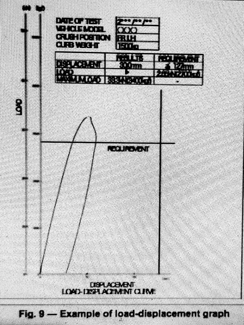
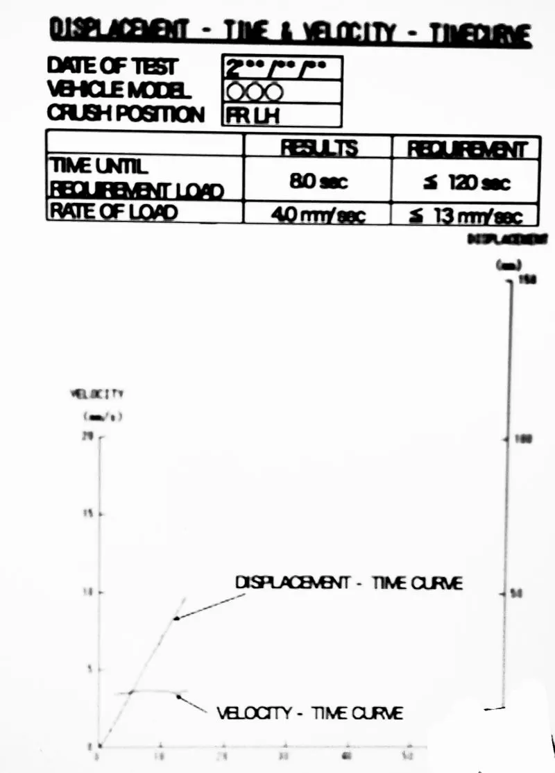
The load device set on the roof side. It displacement is around 127mm and less when a load of 1.5 times the unloaded vehicle weight or 22240 N, which is smaller , is applied. Load device is applied 120 sec.
results by automotive company
load displacement graph
Displacement -time and loading speed- time graph
5. Roof model images
1. outer roof panel
2. front roof rail
master drawing
3. rear roof rail
master section
4. Bow
master section
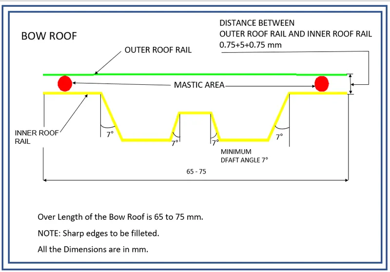
Bow model
5.center Bow
master section
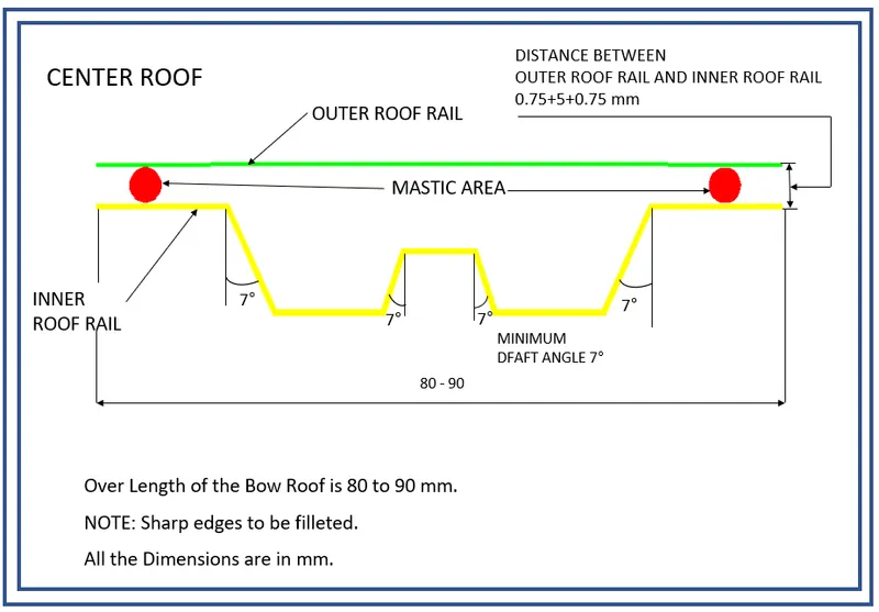
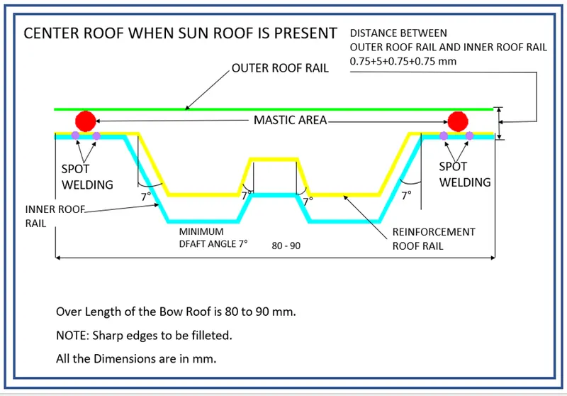
center Bow model
6. roof assembly
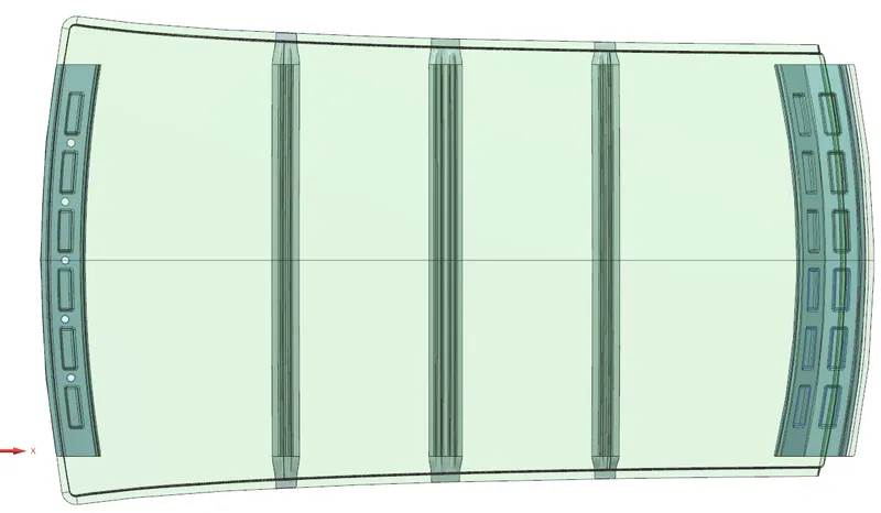
6. Heat distrotion criteria
in this study we test deformation of the car roof when sun tempurature is effecting the outer plate of roof and it is deform, it size change by the tempurature change.
this study is done to check the ability of the roof to withstand high temperature with respect to the positioning of the reinforcements which contribute to increased strength.
Bow–Roof Prediction Formula
W = [1.73 x 10^(-3) x L] + [1.85 x 10^(-8) x (R^2)/t] + [ 1.10x10^(-3) x l] - 2.68
Where,
L = Roof Length in X-Direction[mm](Roof dimension in 0-Y)
R = Roof curvature
R = 2(Rx*Ry)/(Rx+Ry)
Rx = X curvature
Ry = Y curvature
t = Roof plate thickness [mm]
l = Bow Roof Span [mm]
Judgment Condition
OK< 2.7
below figure shows that arc between the rails and bow. these arc radius is shown below.
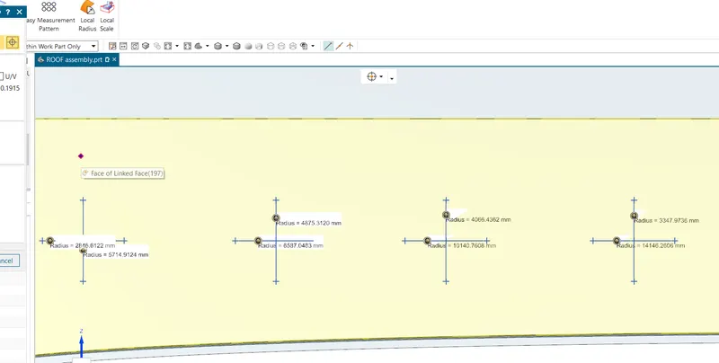
length of the roof
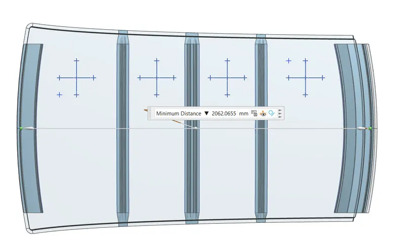
| SECTION | RX | RY | R=2((R*RY)/(RX+RY)) | t=ROOF PLAT THICKNESS | L= ROOF LENGTH IN X- DIRECTION | I= BOW ROOF SPAN | W=((1.7*10^(-3)*L)+(1.85*10^(-8)*((R^2)/t)+(1.1*10^(-3)*I)-2.68)) |
| FRR-BW1 | 5714.91 | 2846.61 | 3800.287789 | 0.75 | 2062.06 | 479.42 | 1.70910462 |
| BW1-CTR | 4875.31 | 6587.04 | 5603.364403 | 0.75 | 2062.06 | 332.28 | 1.965486418 |
| CTR-BW2 | 4066.43 | 10140.76 | 5805.045289 | 0.75 | 2062.06 | 332.25 | 2.02220792 |
| BW2-RRR | 3347.97 | 14146.26 | 5414.499991 | 0.75 | 2062.06 | 452.84 | 2.046773984 |
as per the conditon all section is pass.
7. Snow load criteria
snow load criteria study is done to check the withstand ability when the snow loads over the roof during winter in snow fall regions. this study will also analyse the roof that whether the permanent deformation occurs after removing the snow load .that it may bend but needs to be bounce back to its original position.
Snow Load Prediction Formula
Qr = [Iy x t2] / [α x s x [(Rx + Ry)/2]2 x 10-8]
Where,
α = My x Lx2 x 10-12 , My = Y(Ly-Y)
t = Roof plate thickness [mm]
Ly = Distance between the front and rear roof Rails on the Vehicle along with 0Y[mm]
Length of Roof panel with the center point between Roof rail Front /Rear as the front and rear reference point.
Lx = Distance between the Left and Right end of the roof on the Roof BOW [mm]
The width of the roof panel is exposed on the surface.
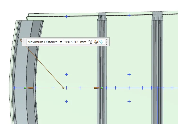
Y = Distance front Front Roof Rail to Roof BOW[mm]
s = Distance for which Roof BOW bears divided load [mm]
s = L1/2 + L2/2
Iy = Geometrical moment of inertia of Roof BOW (Y cross-section )[mm4]
Rx = Lateral direction curvature radius of roof panel Y cross-section on Roof BOW [mm]
Roof panel curvature Radius of the Length Lx in Front view
Ry = Longitudinal Direction curvature radius of the Roof panel X cross-section on Roof BOW [mm]
Roof panel X curvature radius of length s in Side view
Judgment condition
Qr ≥ 3.1
250 ≤ s ≤ 380
for the Rx and Ry we see below image
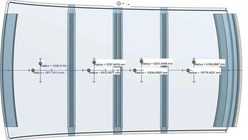
Lx is distance between the front rail to bow center
Lx1
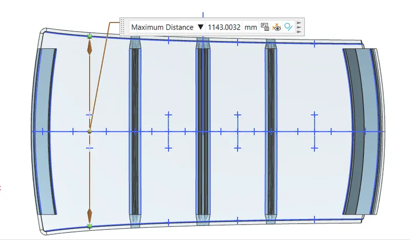
Lx2
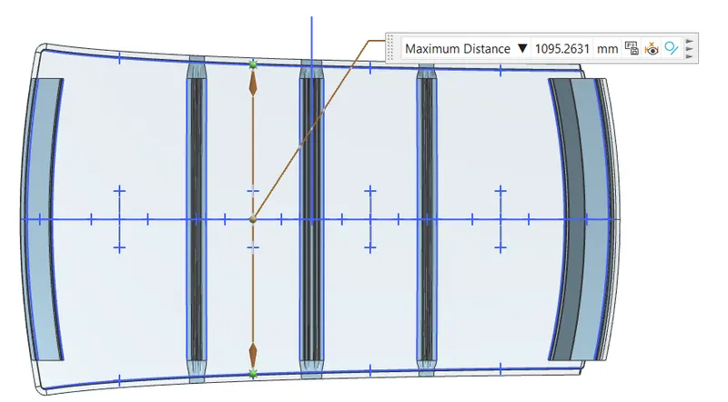
Lx3
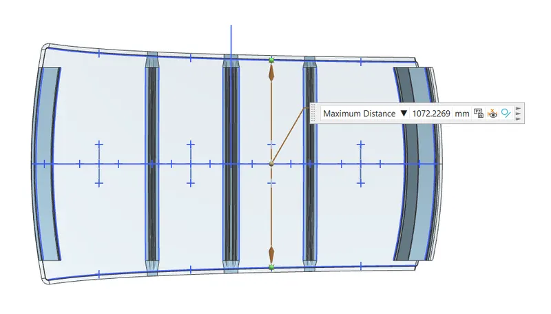
Ly is length in y direction
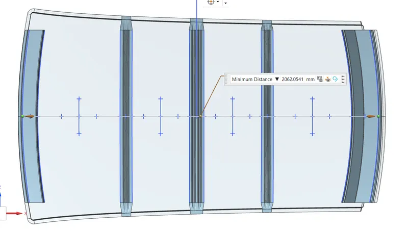
y is distance between the rails
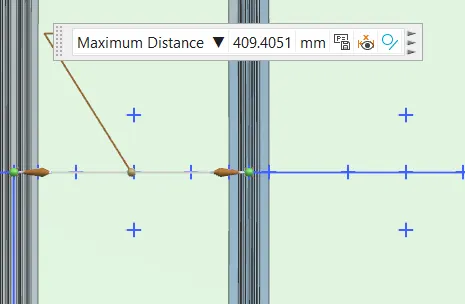
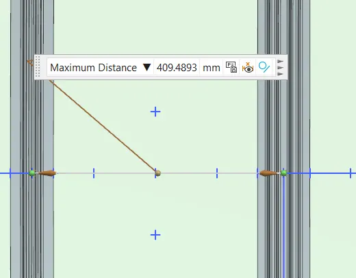
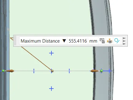
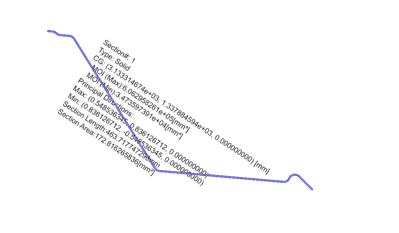
moment of inertia for the rails
front rails
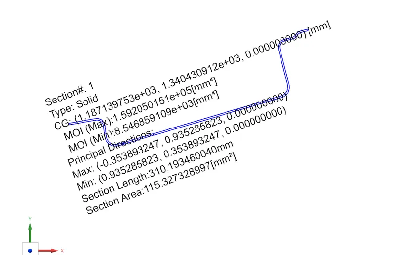
rear roof rails
Bow 1
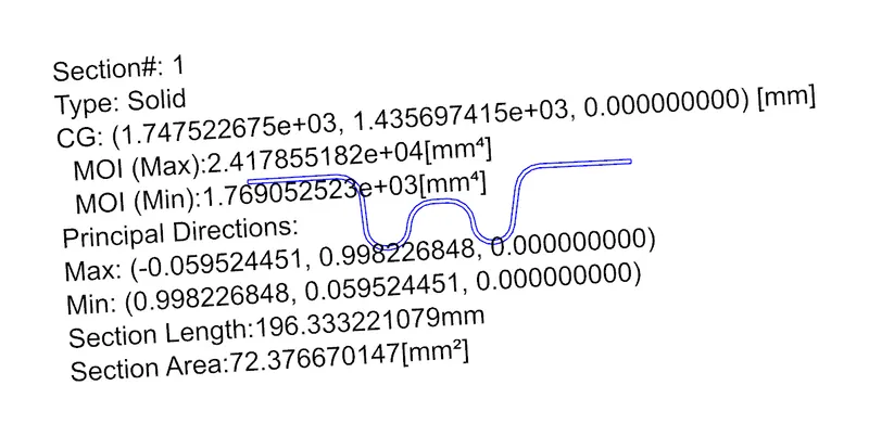
CENTER BOW
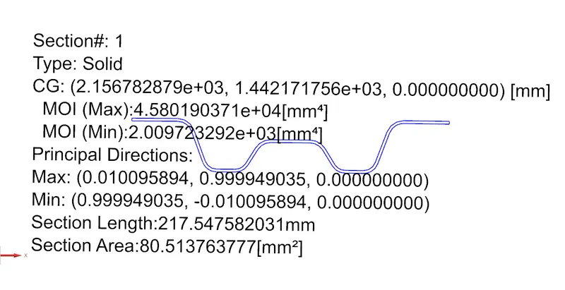
BOW 2
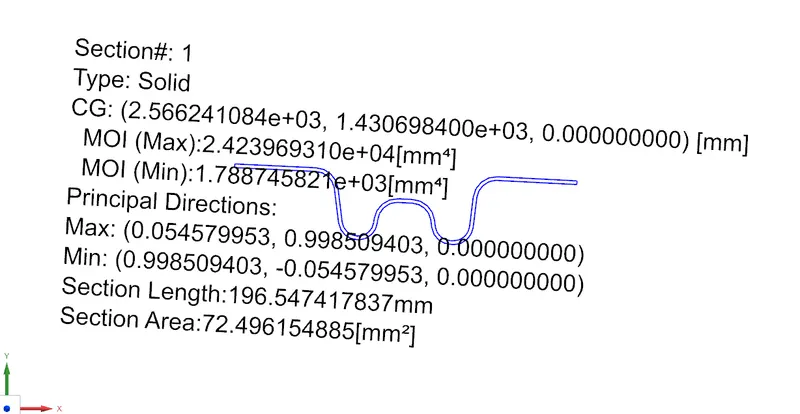
calculation FOR snow load
| section | RX | RY | [(Rx+Ry)/2]^2 | LX | LY | Y | L1 | L2 | S | IY | t | My | α | Qr | condition |
| FRR & BW1 | 4356.81 | 2871.16 | 13060887.58 | 1143 | 2062.05 | 566.59 | 555.41 | 409.4 | 482.405 | 1769.05 | 0.75 | 847312.7 | 1.106971 | 14.267306 | ok |
| BW1 & CTR | 3787.64 | 6512.95 | 26525538.59 | 1095.26 | 2062.05 | 409.4 | 409.4 | 409.48 | 409.44 | 1788.74 | 0.75 | 676594.9 | 0.81164 | 11.4143737 | ok |
| CTR & BW2 | 4231.44 | 10544.69 | 54583504.44 | 1072.22 | 2062.05 | 409.48 | 409.48 | 566.59 | 488.035 | 2009.72 | 0.75 | 676694.4 | 0.777966 | 5.45488162 | ok |
| BW2 & RRR | 4106.06 | 15778.42 | 98848136.22 | 1057.13 | 2062.05 | 555.41 | 566.59 | 0 | 283.295 | 0.75 | 836802.9 | 0.935147 | 0 |
as per snow load condition all cases are pass.
8. Some manufacturing process use in automotive company
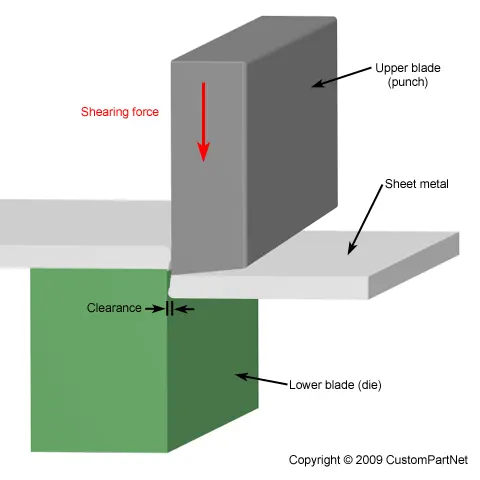
- Shearing, also known as die cutting, is a process that cuts stock without the formation of chips or the use of burning or melting. Strictly speaking, if the cutting blades are straight the process is called shearing; if the cutting blades are curved then they are shearing-type operations. The most commonly sheared materials are in the form of sheet metal or plates. However, rods can also be sheared. Shearing-type operations include blanking, roll stilling, and trimming.
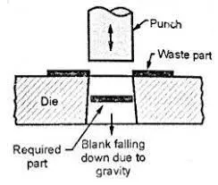
- Punchingis a forming process that uses a punch press to force a tool, called a punch, through the workpiece to create a hole via shearing. Punching is applicable to a wide variety of materials that come in sheet form, including sheet metal, paper, vulcanized fibre and some forms of plastic.
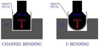
- Bendingis a manufacturing process that produces a V-shape, U-shape, or channel shape along a straight axis in ductile materials, most commonly sheet metal.
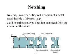
- Nothing is a shearing-related metalworking process that involves the use of a punch press to selectively cut unwanted material from the outer edges of a workpiece. After the workpiece is secured in place, the punch press cuts away the unwanted material from its outer edges using a cutting tool. The end result is a smaller workpiece with a different shape.
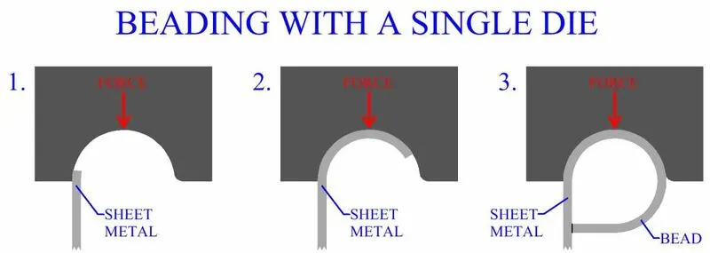
- Beading is one of the common bending operations which are used to form beads at the end of the sheets. In beading, the periphery of the sheet metal is bent into the cavity of the die as shown in following figure. A bead or a round corner is formed at the end of the sheet.
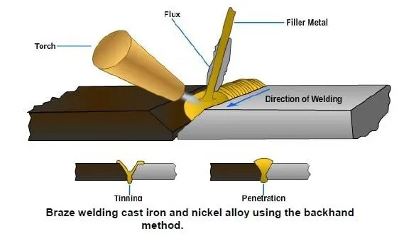
- Welding is a fabrication process whereby two or more parts are fused together by means of heat, pressure or both forming a join as the parts cool. Welding is usually used on metals and thermoplastics but can also be used on wood. The completed welded joint may be referred to as a weldment.
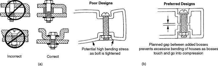
- Fastening is one temporary joining process that employs additional elements to mechanically assemble or attach two or more parts together. Additional mechanical elements that are used for fastening is called fasteners. There are three main types of threaded fastener; Bolts, Screws and Studs. Bolts have a head on one end (this is usually a hex head) and are threaded on the other. They are generally used in conjunction with a nut (and sometimes a washer) to hold them in place.
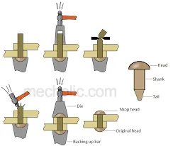
- A rivet is a permanent mechanical fastener. Before being installed, a rivet consists of a smooth cylindrical shaft with a head on one end. The end opposite to the head is called the tail. On installation, the rivet is placed in a punched or drilled hole, and the tail is upset, or bucked, so that it expands to about 1.5 times the original shaft diameter, holding the rivet in place.
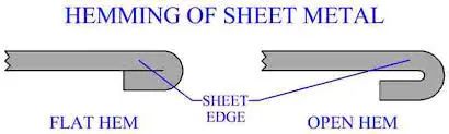
- Hemming is the process in which the edge is rolled flush to itself, while a seam joins the edges of two materials. Hems are commonly used to reinforce an edge, hide burrs and rough edges, and improve appearance.
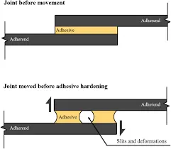
- Adhesive bonding is a joining process for metals and non-metals that uses and adhesive or glue, typically in the form of a liquid or a paste. It offers the major advantage of being able to join a wide array of materials, but is limited by joint strength and applicable service conditions.
9. conclusion
In this project we have discussed about the roof, roof design consideration and their sub components. we have created 3D model roof with using of Nx CAD software. we shown that front roof rail, rear rails, center bow and aditional bow how they are increased the strength of the roof. we have calculated Heat distrotion formula and all cases are pass and their values are under the condition. also we done snow load criateria, all cases is pass. we have writed some manufacturing processes which is using by the automotive industry for the roof manufacturing.