Roof Design
Roof Design
Objective:
- To design a car roof from the given styling roof and also creating the reinforcements like center roof rail, bow roofs by following the given master section.
- To do a curvature study on the roof and perform a calculation to determine the position of bow roofs.
- To determine the heat distortion and snow load criteria of the roof.
- To perform the draft analysis of a developed reinforcements.
Software Used: Nx 12.0
Introduction:
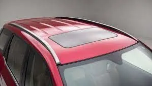
An automobile roof or car top is the portion of an automobile that sits above the passenger compartment, protecting the vehicle occupants from sun, wind, rain, and other external elements. Because the earliest automobiles were designed in an era of horse-drawn carriages , early automobile roofs used similar materials and designs.
Types of Roof:
- Hardtops
- Sunroof
- Convertibles
- The T-Top roofs
Design Consideration
- Visibility criteria
- Head clearance
- Curvature study
- Heat distortion and Snow load criteria
- Draft analysis.
Components of Roof:
- Front Roof rail
- Rear roof rail
- Center roof rail
- Bow roof 1
- Bow roof 2
1.Front Roof Rail:
Master section:
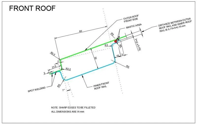
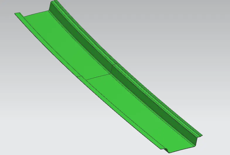
The front roof rail is located on the front of the roof where the wind shield joins with the roof. The visibility criteria and the head clearance of the passenger are taken into consideration for the bottom flange. The end the front roof rail is joined with the roof by spot welding and the mastic sealants for increased strength. The front roof rail designed by following the master section.
2.Rear Roof Rail:
Master section:
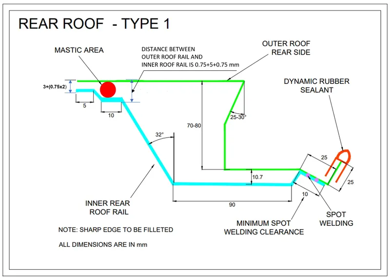
The rear roof rail joins with the back door and the roof. Inputs from the backdoor are taken into consideration for designing this roof rail. Here the spot welding is used to joining the roof outer and rear roof rail. The mastic sealants are used for joining two surfaces.
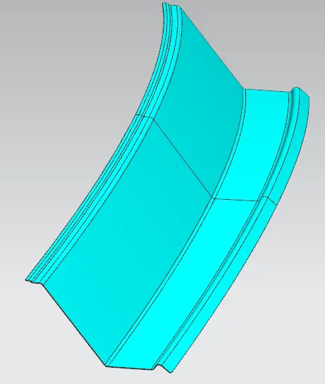
3.Center Roof Rail or Reinforcement Center:
Master section:
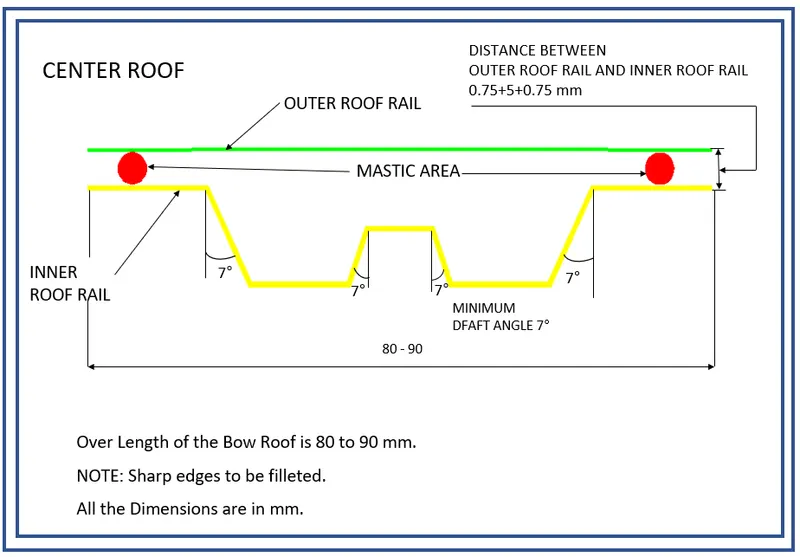
The center roof rail or reinforcement center is placed in center of roof outer which gives more strength to the roof outer. The both end of the center roof rails are joins together with the roof outer ditch area using spot welding and also the mastic sealants are provided with the gaps between the roof outer and the center roof rail.
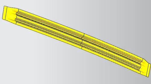
4.Bow Roof 1:
Master Section:
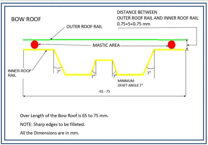
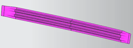
The bow roofs are designed to give more additional strength to the roof outer. The roof 1 is presented in between the front roof rail and the center roof rail. The bow roofs are joins with the roof outer ditch area by using the spot welding and the mastic sealants are provided to give more strength to the roof outer. The bow roofs are designed by following the given master section.
5.Bow Roof 2:
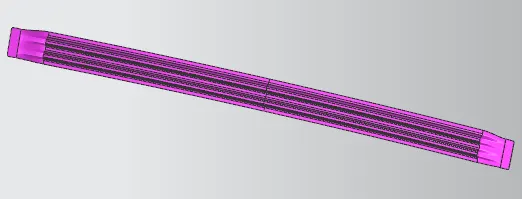
The bow roof 2 are designed by following the given master section. The bow roof 2 are placed between the center roof rail and the rear roof rail. The bow roof 2 is joins with the roof outer ditch area by using the spot welding. The mastic sealants are provided between the bow roof and the roof outer.
Draft Analysis:
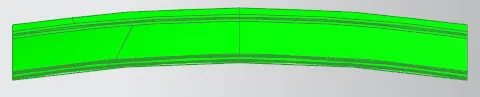
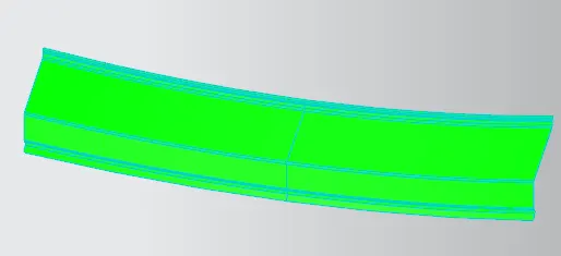
The draft analysis technique is used to analyze whether our part model created in CAD is manufacturable based on the draft condition applied. Here the minimum draft angle applied is 7° degree.
Front Roof Rail:
Rear Roof Rail:
Center Roof Rail:

Bow Roof 1:

Bow Roof 2:

Calculations:
Heat Distortion criteria:
The Heat Distortion is study to check the ability of the roof to withstand high temperature with respect to the positioning of the reinforcements which contribute to increased strength.
Formula:
W=[1.73x10^(-3)x L]+[1.85x10^(-8)x(R^2)/t]+[1.10x10^(-3)xl]-2.68
Where,
L = Roof Length in X-Direction [mm] (Roof dimension in 0-Y)
R = Roof Curvature
R = 2(Rx*Ry)/(Rx + Ry)
Rx = X Curvature
Ry = Y Curvature
t = Roof Plate Thickness [mm]
l = Bow Roof Span [mm]
Judgment Condition
OK<2.7
Table:
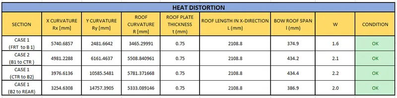
From the above table the roof is satisfying the conditions of heat distortion.
Snow Load Criteria:
This evaluation is performed in cold regions where snow occurs. Roof design must pass through these calculations to ensure that it has sufficient stiffness to withstand the load to accumulation of snow over the roof.
Formula:
Qr = [ly x t2]/[α x s x [(Rx + Ry)/2]2 x 10-8]
Where,
α = My x Lx2 x 10-12 , My = Y(Ly-Y)
t = Roof Plate Thickness [mm]
Ly = Distance between the front and rear roof rails on the vehicle along with O-Y [mm]
Lx = Distance between the left and right end of the roof on the roof bow [mm]
Y = Distance front roof rail to roof bow [mm]
s = Distance for which roof bow bears divided load [mm]
s = (L1/2) + (L2/2)
Iy = Geometrical moment of inertia of roof bow (Y-Cross section) [mm4]
Rx = Lateral direction curvature radius of roof panel Y-cross section on roof bow [mm]
Ry = Longitudinal direction curvature radius of the roof panel X-cross section on roof bow [mm]
Judgement Condition:
Qr ≥ 3.1
Moment Of Inertia Calculation:
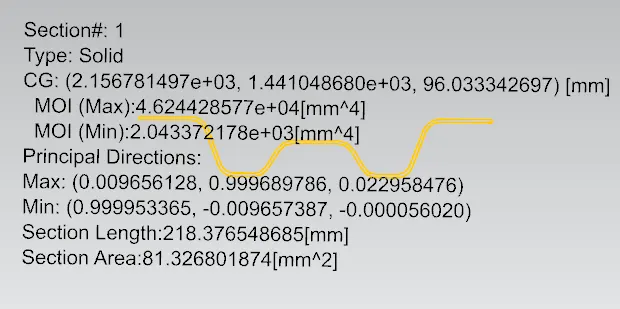
Center Roof Rail:
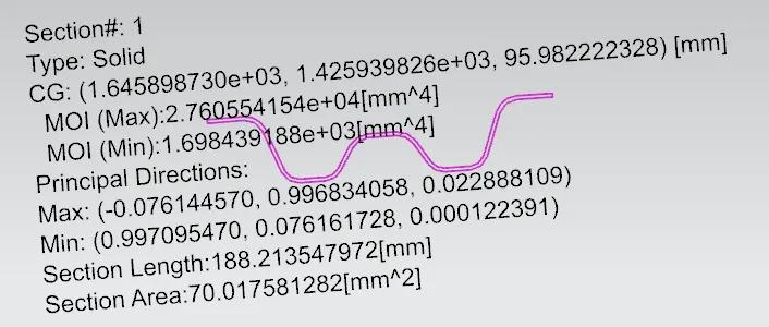
Bow Roof 1:
Bow Roof 2:
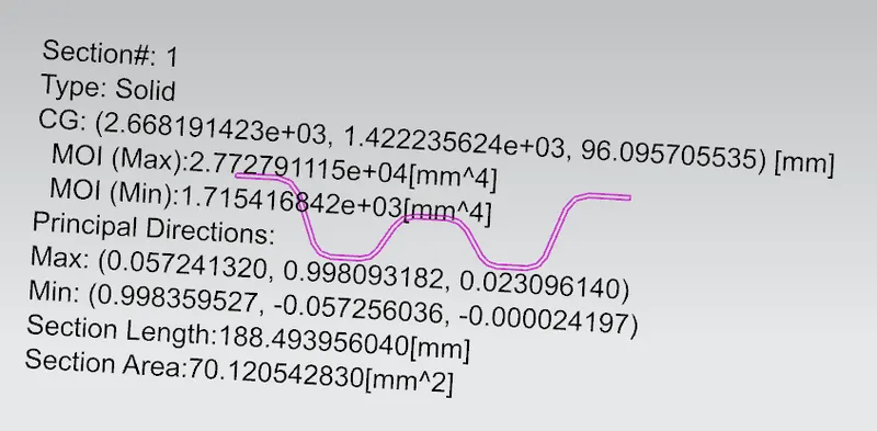
Table:
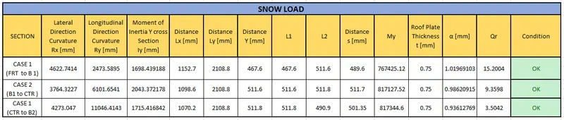
From the above table the roof is satisfying the conditions of snow load criteria.
Conclusion:
Thus the roof was designed with reinforcements like bow roofs & center roof rail by following the given master section and also the curvature study , Draft analysis , Heat distortion, Snow load calculations are completed. The roof is satisfying all conditions.