Roof Design
Objective-
1. For the given Car Roof styling, design and develop the essential flanges and reinforcements, namely the Ditch Area, Front Roof Rail, Rear Roof Rail, Centre Roof Rail and Bow-Roofs.
2. Do a curvature study on the roof and perform calculations for Heat Distortion and Snow load criterion to determine and justify…
Importance of car roof-
Geometric requirements:
- Thickness: 0.75 mm
- Ditch area-minimum flange width: 21.5mm
Manufacturing requirements:
- Small emboss depth should be less than 6 mm
- Mounting and welding areas should be flat
- Minimum fillet radius should be 3mm+thickness
- Tool opening angle is 3 degrees
Functional Requirements:
- Provide adequate space for windshield glass supporting elements
- Space for the hinges of backdoor and allow the swinging of backdoor
1: Creating the Outer panel surface from the given input skin.
2: Developing the ditch area
Flanges are created on four sides of the roof as per the above-mentioned requirements. The front end flange is given with a width of 21.50 mm to provide adequate space for the rubber sealing, mounting of windshield glass, etc. The rear ditch area is created to allocate the hinges of the backdoor and to allow the swinging of the backdoor to the required opening angle. Some embosses are also provided on the rear to increase the strength locally.
2) Front Roof Rail
The front rail supports the roof outer shell at the front end. It is mounted with brace roof rail reinforcement on both ends. The rails are provided with embosses to improve the strength and the rail is connected to the outer panel using mastic sealants on one side and the other joinery is spot welded.
Design Considerations:
Geometric requirements:
- Thickness – .75 to 1.5 mm
Manufacturing requirements:
- Small emboss depth should be less than 6 mm
- Mounting and welding areas should be flat
- Minimum fillet radius should be 3mm+thickness
Functional requirements:
- Headroom clearance: 80 mm minimum
- Front visibility criteria
- Enough flange length to support the windshield glass & its components
- 2 mm clearance at the flange edge for trims.
Design methodology
1: Creating the swept surface that meets the design requirements with the outer surface geometry as reference.
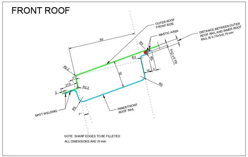
The section is created by considering the front visibility criteria and minimum headroom clearance of 80mm. A flange of 15 mm is provided to support the windshield glass & its components,
And 2 mm clearance is provided at the flange edge for allocating the trims.
Section Modulus Analysis of Front section:
Section Modulus S = I/Y
DESIGN OF ROOF
- Outer panel
An outer panel is the outermost sheet metal of the roof in which there are aerodynamic cut-outs or sunroof cut-outs or etc. And there can be some fixtures or carriages to carry luggage on top of the car.
The thickness of the sheet metal of the outer panel should be around 0.75 mm and the flange area for the ditch should be minimum 15 mm.
Material – SP121AQ (Cold Rolled Mild Steel)
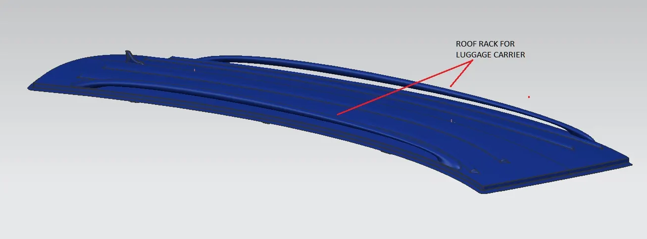
- Front roof rail
A front roof rail is a reinforcement placed on the front section of the roof. This reinforcement connects with side sections of the car and it also attaches with the front windshield of the car. With the available master section of the front rail. To increase the strengthens an emboss operation is also performed while modelling.
A model is designed with the following specifications-
Material – SP783AJQ (Terrace Zinc Galvanizing)
Thickness – 0.75 mm
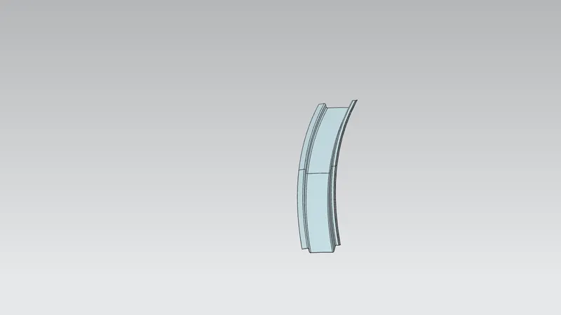
Draft Analysis
In the real-world application of manufacturing of sheet metals with some operations like hot and cold rolling, punching etc. The angle modelled in the CAD software for this component should be applicable for the real-world manufacturing processes also.
So, in the CAD software, some analysis can be made to precheck the operations that can be performed in Manufacturing industries. Draft analysis is one of the analyses that check the angle between the components which are operated in sheet metals.
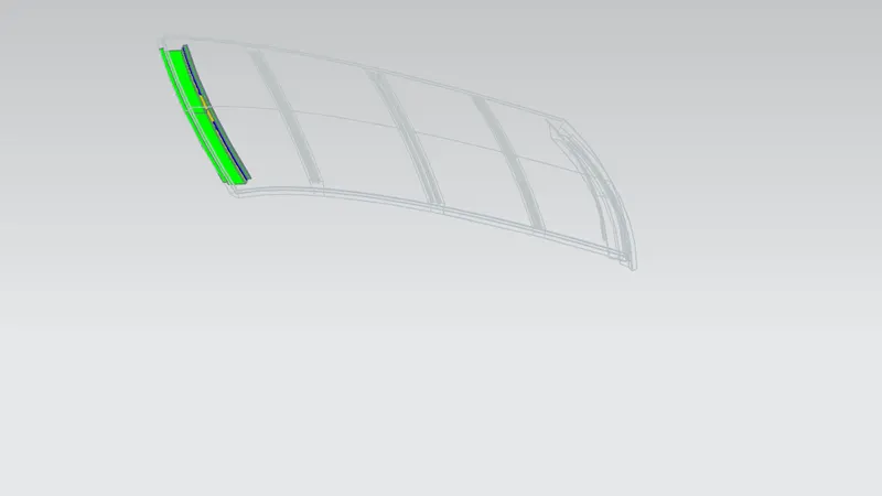
- Bow roof rail (front)
The front area for the bow roof rail is placed between front roof rail and centre roof rail reinforcements. This component main purpose is to strengthen the flattest surface on the roof available. so, wherever there is a flat surface on the roof rail reinforcement can be introduced. This bore roof rail front is fixed with both sides of the car.
Material – SP121BQ (Cold rolled steel coil)
Thickness – 0.75 mm
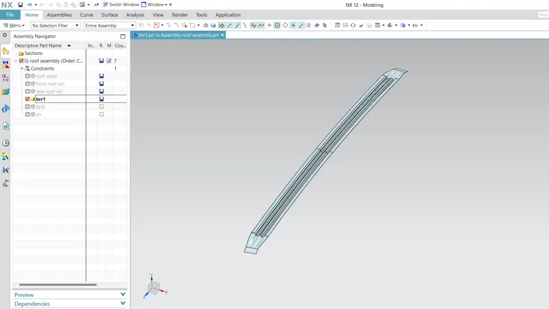
Draft Analysis
In the real-world application of manufacturing of sheet metals with some operations like hot and cold rolling, punching etc. The angle modelled in the CAD software for this component should be applicable for the real-world manufacturing processes also.
So, in the CAD software, some analysis can be made to precheck the operations that can be performed in Manufacturing industries. Draft analysis is one of the analyses that check the angle between the components which are operated in sheet metals.
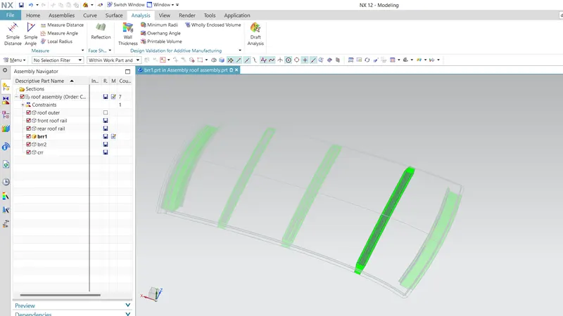
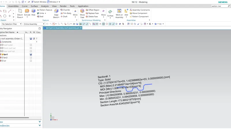
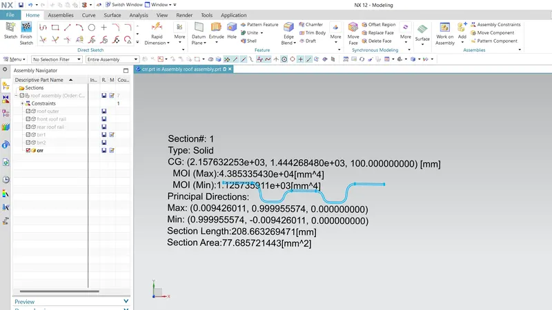
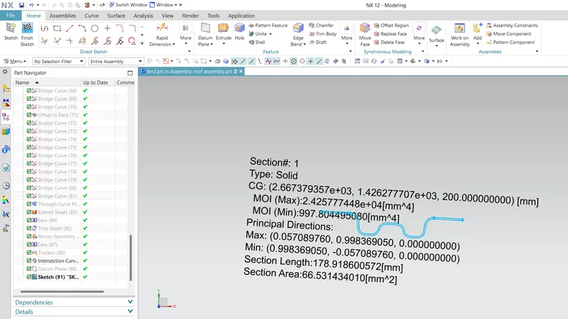
Section Inertia modulus Analysis
Section modulus is a geometric property for a given cross-section used in the design of beams or any component with flexural properties. Other geometric properties used in the design include an area for tension and shear, the radius of gyration for compression, and moment of inertia and polar moment of inertia for stiffness.
So, for the section of the front roof rail component a section inertia modulus analysis made to check the elastic properties or the deformation properties on the component.
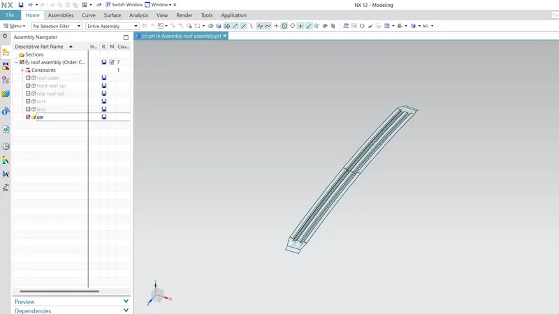
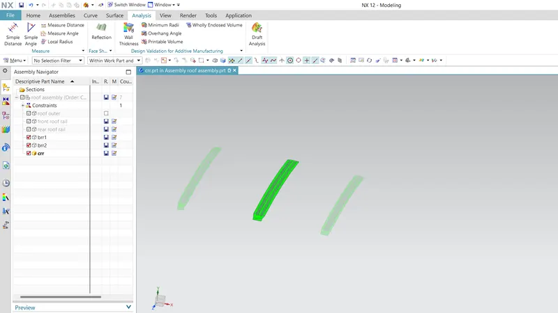
- Centre roof rail with reinforcement
This component is also one of the bow rails that protect the car and as well as also the passengers from the roll-over accident or test. This component has also some of the Properties that can be attached to this reinforcement centre rail Like clamp for the compartment inside or attaching a fan etc.
This particular roof rail is important because a roof’s flattest area can we identify at the centre so for this reinforcement, there should be some importance given to it. so that's why it has two reinforcement attached to the outer panel.
Material – SP153 – 980 PQ (Cold Rolled JIS Steel)
Thickness – 0.75 mm (both)
- Bow roof rail (back)
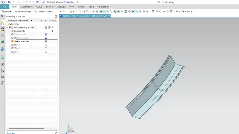
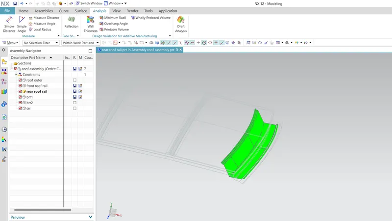
The back area for the bow roof rail is placed between back roof rail and centre roof rail reinforcements. This component main purpose is to strengthen the flattest surface on the roof available. so, wherever there is a flat surface on the roof rail reinforcement can be introduced. This bore roof rail front is fixed with both sides of the car.
Material – SP121BQ (Cold rolled steel coil)
Thickness – 0.75 mm
Draft Analysis
Section inertia modulus
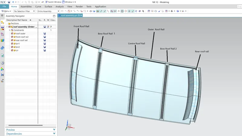
Assembly of the roof with all reinforcements
- CALCULATION OF BOW ROOF REINFORCEMENT PREDICTION
HEAT DISTORTION FORMULA
W = [1.73 x 10^ (-3) x L] + [1.85 x 10^ (-8) x (R^2)/t] + [ 1.10x10^ (-3) x l] - 2.68
Where
L = Roof Length in X-Direction[mm](Roof dimension in 0-Y)
R = Roof curvature
R = 2(Rx*Ry)/(Rx+Ry)
Rx = X curvature
Ry = Y curvature
t = Roof plate thickness [mm]
l = Bow Roof Span [mm]
the curvature design criteria are OK if ‘W’ is: OK< 2.7> 3.1
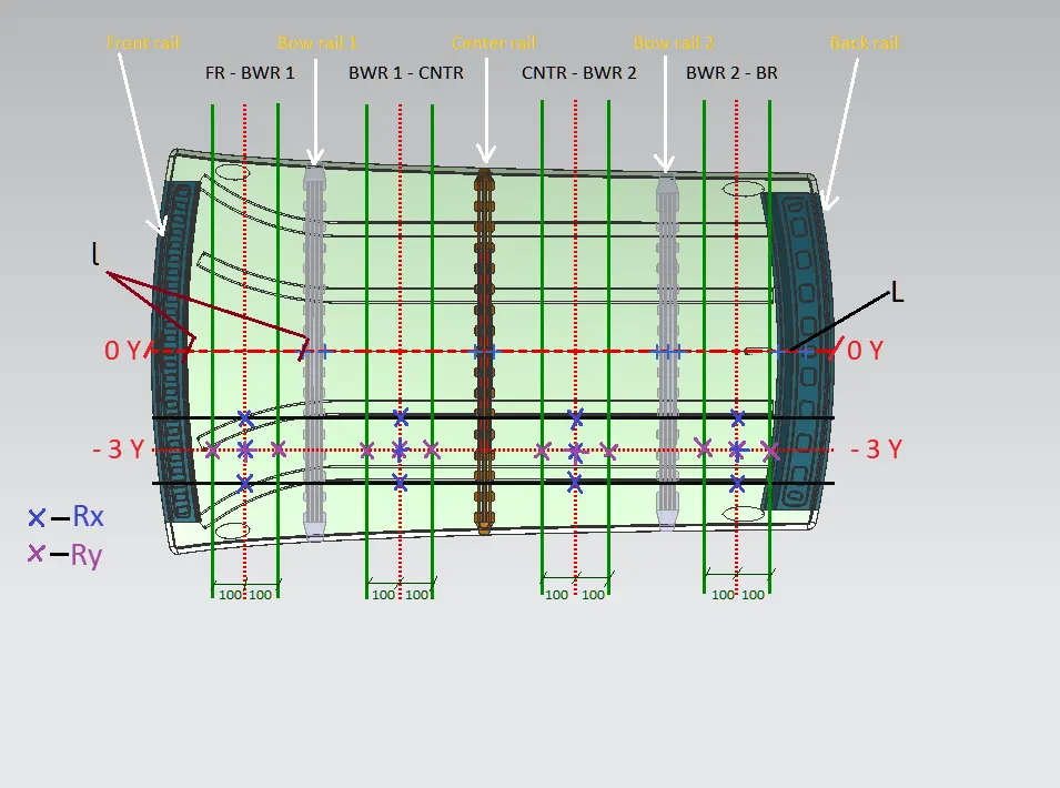
Heat distortion Calculation table
Heat distortion test is a type of static load test which plays an important role in maintaining roof strength. Heat distortion temperature is the temperature at which metal softens and deforms under a specified load. From Heat distortion criteria, roof strength can be enhanced by appropriate positioning of bow roof rails.
|
Snow load criteria-
The snow load test is a type of static load test used to verify that roof assembly exhibits no permanent deflection due to a distributed load representing snow load: the distributed pressure applied is in the range 10-15 N/dmᶺ2.
Qr = [Iy x t2] / [α x s x [(Rx + Ry)/2]2 x 10-8]
α = My x Lx2 x 10-12 , My = Y(Ly-Y)
t = Roof plate thickness [mm]
Ly = Distance between the front and rear roof Rails on the Vehicle along with 0Y[mm]
Length of Roof panel with the center point between Roof rail Front /Rear as the front and rear reference point.
Lx = Distance between the Left and Right end of the roof on the Roof BOW [mm]
The width of the roof panel is exposed on the surface.
Y = Distance front Front Roof Rail to Roof BOW[mm]
s = Distance for which Roof BOW bears divided load [mm]
s = L1/2 + L2/2
Iy = Geometrical moment of inertia of Roof BOW (Y cross-section )[mm4]
Rx = Lateral direction curvature radius of roof panel Y cross-section on Roof BOW [mm]
Roof panel curvature Radius of the Length Lx in Front view
Ry = Longitudinal Direction curvature radius of the Roof panel X cross-section on Roof BOW [mm]
Roof panel X curvature radius of length s in Side view
Qr>3.1 =ok
| Sr No | Position | Ly | Alpha | Lx | Iy | y | My | s | Rx | Ry | T | Qr | Result |
| 1 | Bow roof 1 | 2027.85 | 0.6925 | 1145 | 1.008e03 | 387.65 | 635823 | 483.26 | 4752 | 2379 | 0.75 | 10.53 | Ok |
| 2 | Centre roof | 2027.85 | 1.218 | 1090 | 1.125e3 | 966.58 | 1025802 | 543.5 | 3759 | 5780 | 0.75 | 4.22 | OK |
| 3 | Bow roof 2 | 2087.85 | 0.9083 | 1056 | 997.8044 | 1476 | 814530.6 | 502.55 | 4279 | 11089 | 0.75 | 2.09 | NG |
Conclusion -Design succesfully created accourding to Heat to heat distoration criteria.
In case snow load criteria Bow roof 2 result is NG
Solutions-1)Increase the thickness of Bow roof 2 then increase the of Iy & result will be ok
2) Change the position Bow roof 2