Roof Design
Design a Roof with its components by following the master section of the front roof rail (at least 1 Front roof rail, two bow roofs, 1 centre roof rail and 1 rear roof rail) with all the design parameter mentioned in the videos. Need to include all Part files and assembly file as a zip file along with the report.
ROOF
Car roof is the important composition parts of Integral automobile, and the fastness of car roof is directly connected to the quality of car performance;
The processing technology of roof directly has influence on the anti-seismic performance of soundproof effect and the car of car inside;
Therefore, when processing roof, often adopt many roofs can’t rail acting’s in conjunction to guarantee the integral firmness of roof; Prevent the distortion of car body.
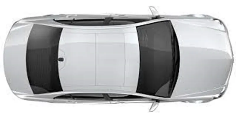
MANUFACTURING TECHINUQUES OF ROOF
Outside plate process: the first step, open straight snips plate: first select applicable cold coiling specification, cold coiling is opened flat; Then according to production material specification, will open cold coiling after flat and be cut into the iron plate of corresponding size; Finally the iron plate after shear is cleaned to iron filings; The first step, oil pressure, punch press: first iron plate is extended; Secondly to its trimming and punching; Then to its flanging and punching; Finally, after punching completes, it is carried out to the operation of side folding; Completed the making of outside plate;
Bar shaped assembly and ring-shaped component process: the first step, blanking, stamps out iron plate the outline blank of many roofs can’t rails, a ring-shaped component and a bar shaped assembly; Second step, carries out annular punching to ring-shaped component: bar shaped assembly and roof can’t rail are carried out to bar shaped punching;
Car roof anabolic process: the first step, by a plurality of M6 nuts of a side spot welding of ring-shaped component; By two M6 nuts of bar shaped assembly two ends spot welding; Second step, spots weld bar shaped assembly the opposite side of the corresponding nut of ring-shaped component; And circular groups and the punching of bar shaped assembly are aimed at; The 3rd step, is welded to ring-shaped component the inner side of outside plate; The 4th step, spots weld roof cant rail the inner side of outside plate; Finally car roof integral body is carried out to sanding thorn and ending.
Trimming and punching in described outside plate process can make a final part
TESTING OF ROOF
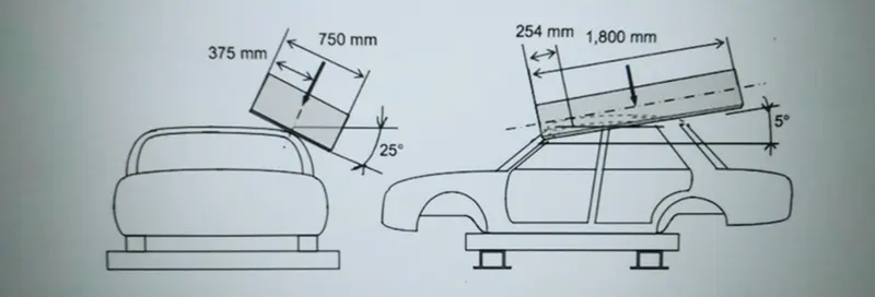
Roof strength evaluations are conducted on a quasi-static test systems manufactured by MGA Research corporation
The system consists of an upright assembly and an attached loading head that can be fixed at varying height from the ground as well as at pitch angles ranging from – 5to+5 degrees to accommodate testing on the driver or passenger side
The roll angle is permanently fixed at degrees. Four hydraulic actuators control the movement of the plant along two linear guides the entire systems is mounted on a T-slot bed plate anchored to the floor of the test facility
DESIGN OF ROOF
In the car roof consist of several component there are,
- ROOF OUTER PANEL
- FRONT ROOF
- REAR ROOF
- CENTER ROOF
- BOW ROOF 1
- BOW ROOF 2
ROOF OUTER PANEL
The roof outer panel can be designed with the help of master section on the styling surface
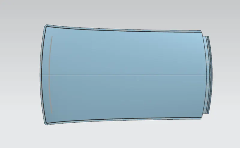
FRONT FACE
- We take styling surface in to half then untrim the surface to remove holes on the surface
- Extracting the untrim surface then take as a working surface
- law extension -Extending the corner surface at the angle of 7 degree outward and also extend a side corner of 7 degree outward
- Extend sheet – The above two corner has been extended
- Trim and extend -The unwanted extra sheet has been removed
- Edge blend-To avoid the sharp corner to make a perfect blend at the radius of 3.75 and another law extension has been done
- Bridge curve-To connect the two-surface using the curves
- Through curve mesh-By using that to fill the gap between the surface with the help of curves
REAR FACE
- The following operation same as the front face additionally some tools are used
- General law extension has done based on the requirement
- Offset surface: The styling surface has been offset to 80mm
- Offset curve in face: The curve has been offset to 50 mm
- Trim sheet: To remove the unwanted surface by the help of boundary
- Sew: By joining the two sheets into single sheet
- Datum plane: To create a plane at a distance of 480 mm
- Intersection curve: create a intersection curve based as an reference of using a datum plane
- Trim sheet: To trim the sheet for making the feasibility for mounting A PILLAR
- Edge blend: to remove sharp corner
- Mirror geometry’s: To make a symmetric geometry
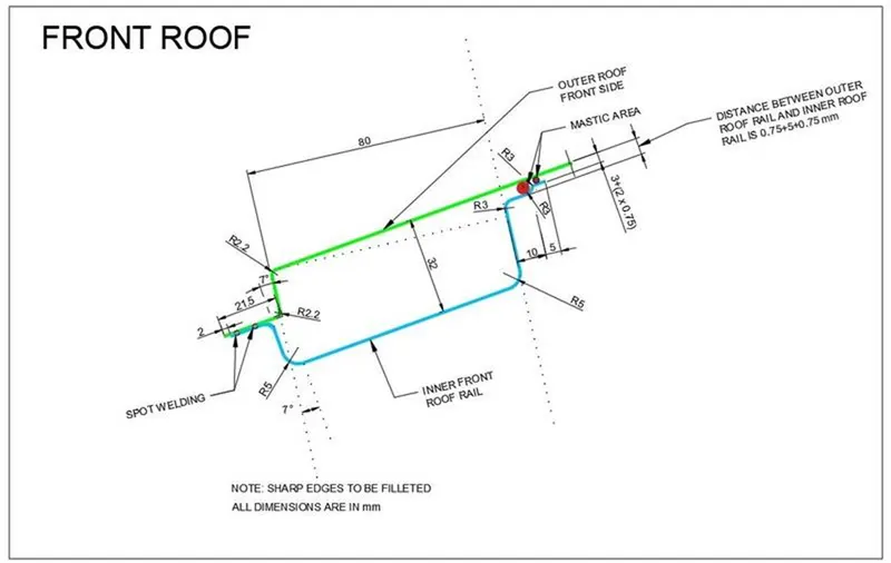
FRONT ROOF
In that styling surface has been imported from reference surface
Based on the above operating tools also used to create a front roof section additional added tool are
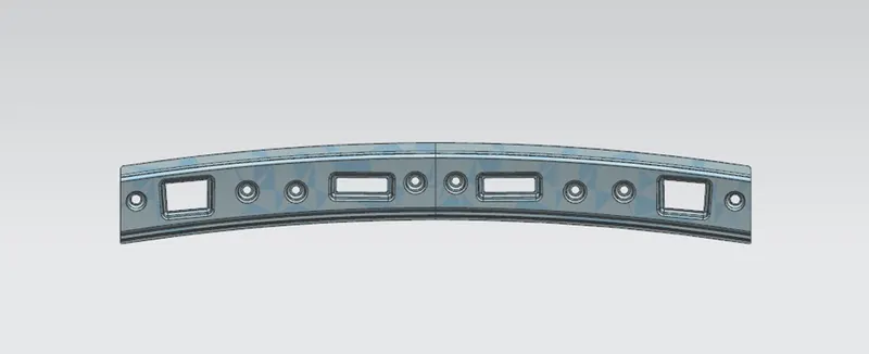
Wave geometry linker: Taken a required surface from reference surface
Projecting curves: TO project the sketches to the selected body using the vector as a reference
Emboss: To strengthen the surface, to create sketch on datum plane, based on the sketch select a face as reference to create emboss
Thicken: Add thickness to the material
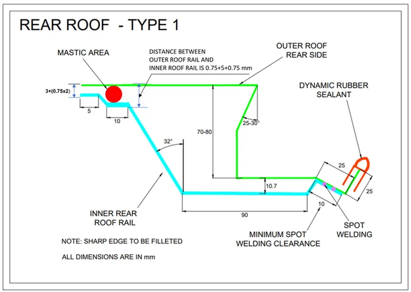
Rear roof:
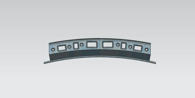
Linear pattern:
SWEPT: By joining the two irregular faces together these commands are used
MASTIC SEALENT: To join the two surfaces
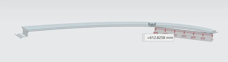
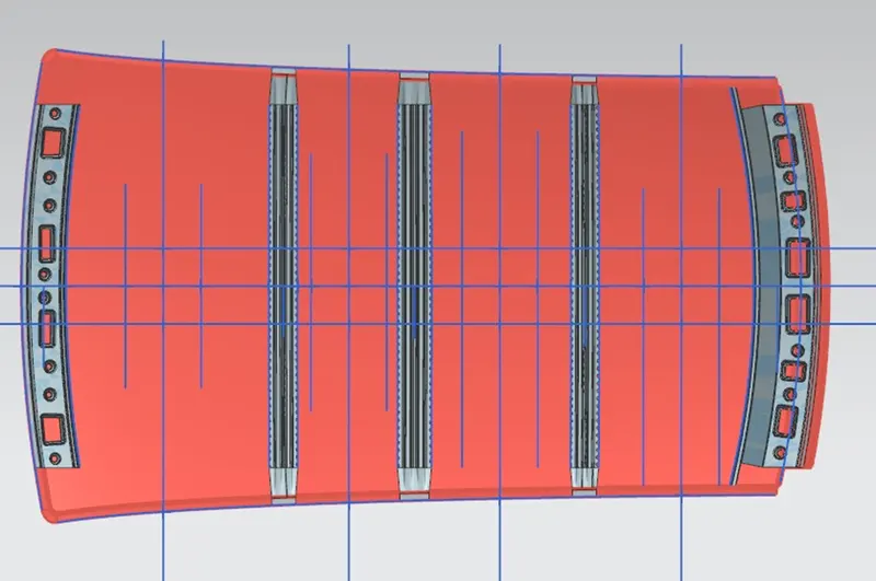
BOW ROOF 1:
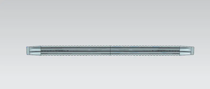
The bow roof one has been fixed at a distance of 600 mm, because the flat surface start from the distance. The flat surface requires more strength than the curved surface
BOW ROOF 2
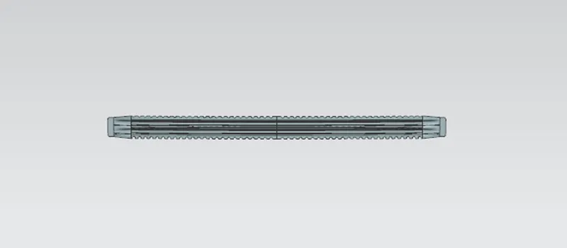
The above design is to be check whether the design is safe or not
TO calculate the Heat Distortion study and Bow–Roof Prediction Formula
Heat Distortion study
The heat distortion study plays a major role in sheet metal usage. Heat distortion temperature is a temperature limit above which the material cannot be used for the structural applications. This study is used to predict the heat distortion temperature at where the material starts to soften when exposed to a fixed load at elevated temperature. In order to avoid bending or damages on the roof, based on the heat distortion temperature, this study will predict the bow roof position which helps to strengthen the roof.
BOW-ROOF PREDICTION FORMULA
W = [1.73 x 10^ (-3) x L] + [1.85 x 10^ (-8) x (R^2)/t] + [ 1.10x10^ (-3) x l] - 2.68
Where
L = Roof Length in X-Direction[mm](Roof dimension in 0-Y)
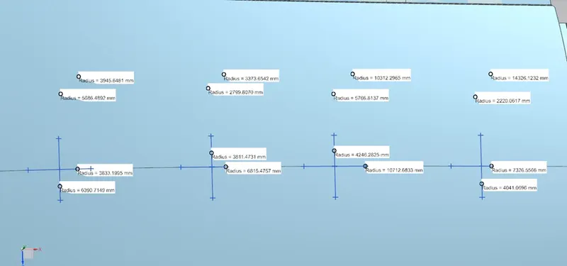
R = Roof curvature
R = 2(Rx*Ry)/(Rx+Ry)
Rx = X curvature
Ry = Y curvature
t = Roof plate thickness [mm]
l = Bow Roof Span [mm]
Judgement Condition:
OK< 2.7
STEPS FOLLOWED TO TAKE A VALUES FROM ROOF
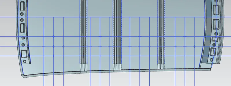
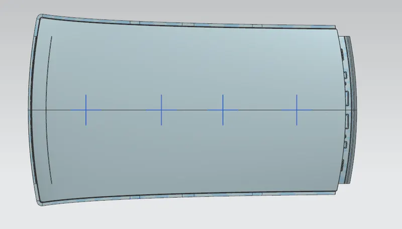
- To select a plane which is parallel located the design file
- Create a horizontal line which is intersecting the middle of the roof
- Take offset of 300mm from the centre line
- Take offset of 100 mm from the offset line
- Projecting the edges of the sub parts and also join using the line
- By join the line also to find the midpoint and generate the vertical line
- By symmetrically offset the line in to 100mm
- To find the point on intersecting line by using intersecting point option
- The point has been projected in the roof body by projecting curve
- To join the point using the arc command
- To find the radius of the arc using the local radius
Calculation
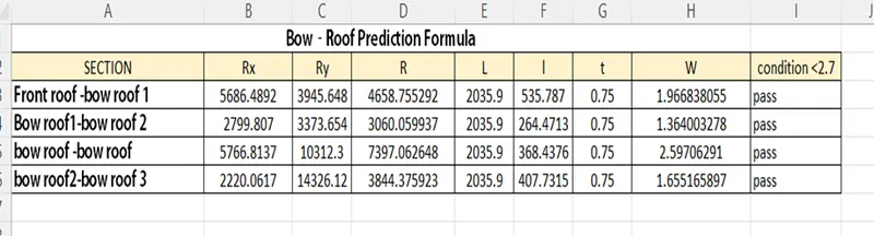
SNOW LOAD CALCULATION
When the winter season the snow will cover the roof of the car. Normally due to snow weight dent will happen. But the roof be designed in such a way, when the snow is removal, the roof goes to the original position. The condition is,
Qr ≥ 3.1
250 ≤ s ≤ 380
Snow Load Prediction Formula
Qr = [Iy x t2] / [α x s x [(Rx + Ry)/2]2 x 10-8]
Note: The Qr value given over here is correct. There was a typo error in the formula given in the video.
Where,
α = My x Lx2 x 10-12 , My = Y(Ly-Y)
t = Roof plate thickness [mm]
Ly = Distance between the front and rear roof Rails on the Vehicle along with 0Y[mm]
Length of Roof panel with the centre point between Roof rail Front /Rear as the front and rear reference point.
Lx = Distance between the Left and Right end of the roof on the Roof BOW [mm]
The width of the roof panel is exposed on the surface.
Y = Distance front Front Roof Rail to Roof BOW [mm]
s = Distance for which Roof BOW bears divided load [mm]
s = L1/2 + L2/2
Iy = Geometrical moment of inertia of Roof BOW (Y cross-section) [mm4]
WE NEED A MOMENT OF INERTIA VALUE
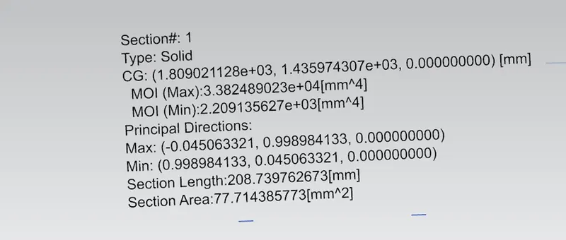
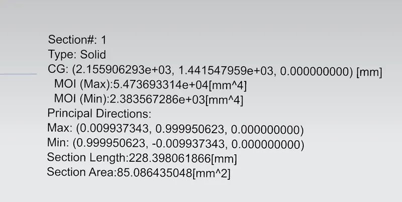
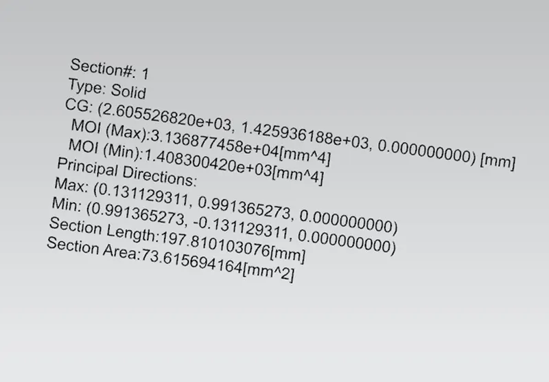
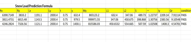
The above following condition has been satisfied the roof design and also we need to check draft analysis:
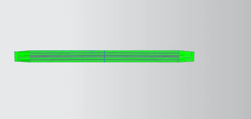
DRAFT ANALYSIS
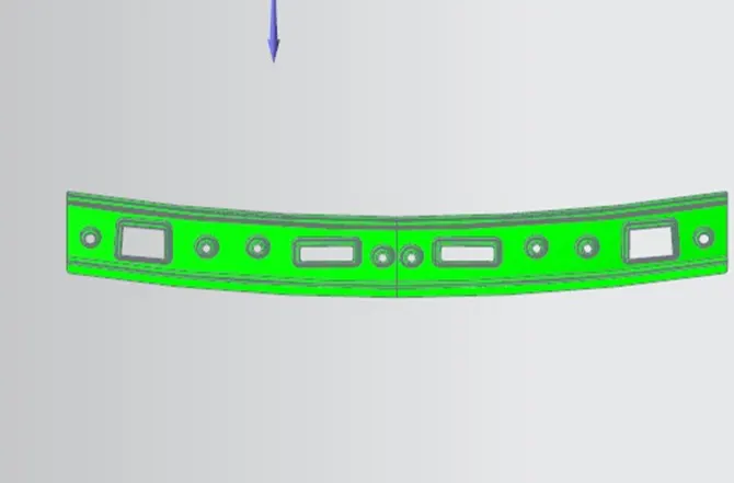
A draft analysis is used to see if the draft of a part is sufficient for the moulding process and if the part will separate correctly from the mould. The draft refers to the angle between the face of a part and the direction of pull (refers to direction of the selected plane/face of a part) of each mould side
FRONT ROOF
REAR ROOF
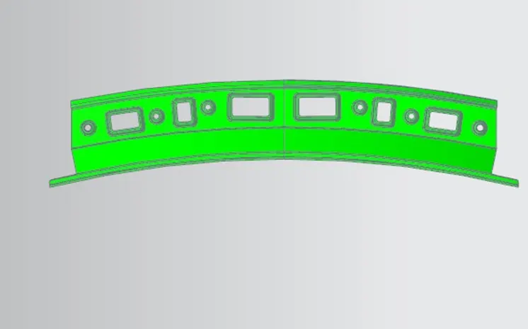
CENTER ROOF
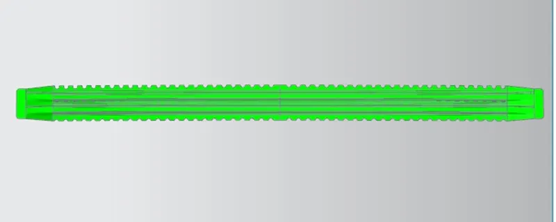
BOW ROOF 1
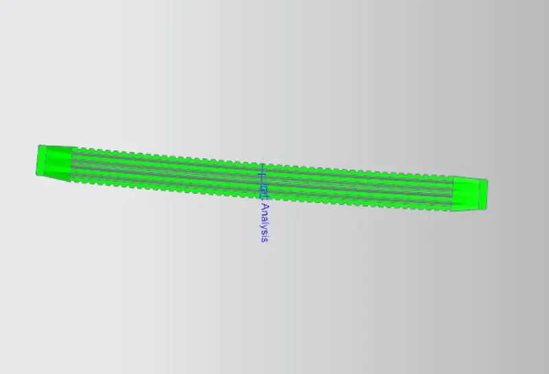
BOW ROOF 2
CONCULSION
Finally we design the roof assembly and also check the heat distortion , snow load calculation criteria and draft analysis; also check the feasibility of manufacturing condition