Roof Design
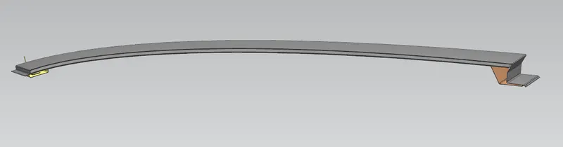
ROOF WITH REINFORCEMENTS:
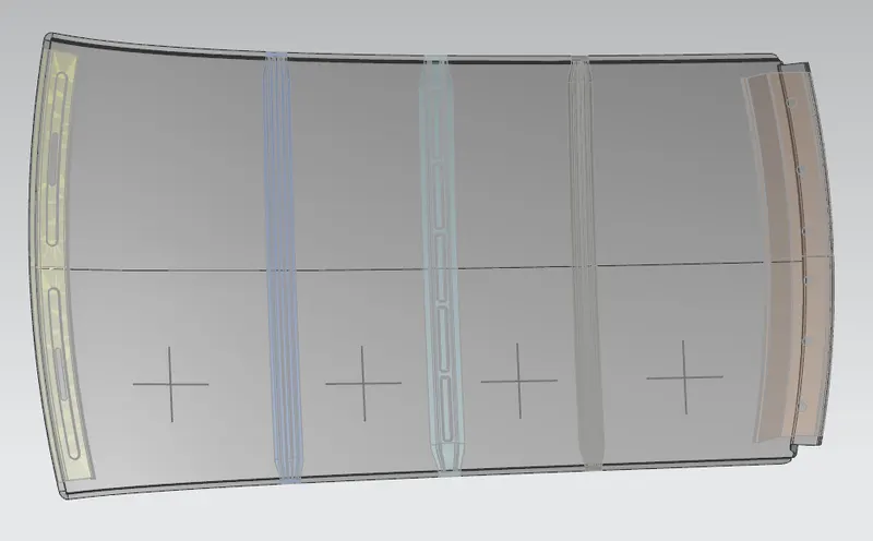
BOW ROOF CALCULATIONS:
W = [1.73 x 10^(-3) x L] + [1.85 x 10^(-8) x (R^2)/t] + [ 1.10x10^(-3) x l] - 2.68
Where,
L = Roof Length in X-Direction[mm](Roof dimension in 0-Y)
R = Roof curvature
R = 2(Rx*Ry)/(Rx+Ry)
Rx = X curvature
Ry = Y curvature
t = Roof plate thickness [mm]
l = Bow Roof Span [mm]
Abbreviations:
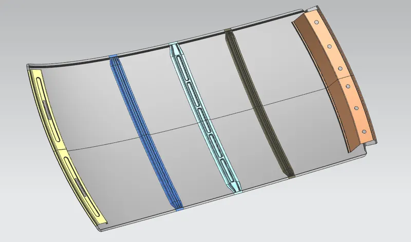
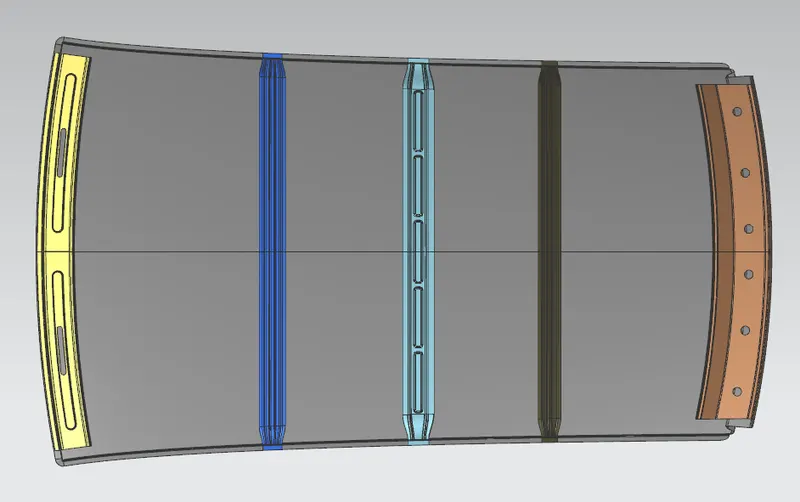
Front roof rail - FRR; Bow roof rail - BRR; Center roof rail - CRR; Rear roof rail - RRR
| Sections | Rx | Ry | R | l | W |
| 1- FRR to BRR1 | 5692.9 | 3013.12 | 3940.58 | 532.04 | 1.79 |
| 2- BRR1 to CRR | 4754.71 | 7072.35 | 5686.44 | 334.87 | 1.99 |
| 3- CRR to BRR2 | 3985.21 | 10551.03 | 5785.27 | 297.6 | 1.98 |
| 4- BRR2 to RRR | 3326.37 | 13794.81 | 5360.21 | 434.18 | 2.01 |
L=2028mm, t=0.75mm
W<2.7 Satisfied for all sections.
NOTE:
- all dimensions are in mm if not mentioned and W is unitless
- BRR1 is in between FRR and CRR
PROCEDURE:
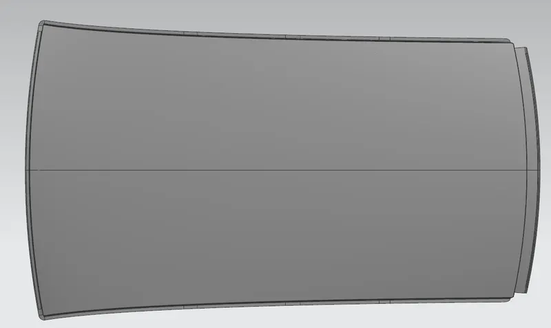
- Here, Y-axis is the horizontal axis spliting the roof into two symmetrical halves & X-axis is perpendicular to that as shown in above picture.
- Curve is taken at 300mm offset from Y-axis onto the left half of roof.
- Along its length of Y-axis, four curves are taken which divide the roof into 5 parts w.r.t. Y-axis. Curves lies within same distance to reinforcement on either sides.
- Then all curves are trimmed on both side at an offset of 100mm each, which results in curves as shown in above picture.
- Now Rx and Ry are measured for each sections using curves obtained.
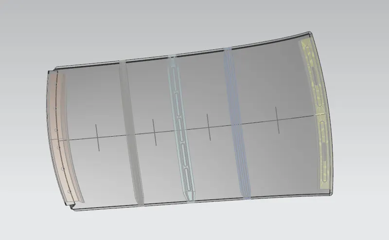
SNOW LOAD CALCULATIONS:
Qr = [Iy x t2] / [α x s x [(Rx + Ry)/2]2 x 10-8]
α = My x Lx2 x 10-12 ,
My = Y(Ly-Y)
Where,
α = My x Lx2 x 10-12 , My = Y(Ly-Y)
t = Roof plate thickness [mm] (0.75mm)
Ly = Distance between the front and rear roof Rails on the Vehicle along with 0Y[mm]
Length of Roof panel with the center point between Roof rail Front /Rear as the front and rear reference point.
Lx = Distance between the Left and Right end of the roof on the Roof BOW [mm]
The width of the roof panel is exposed on the surface.
Y = Distance front Front Roof Rail to Roof BOW[mm]
s = Distance for which Roof BOW bears divided load [mm]
s = L1/2 + L2/2
Iy = Geometrical moment of inertia of Roof BOW (Y cross-section )[mm4]
Rx = Lateral direction curvature radius of roof panel Y cross-section on Roof BOW [mm]
Roof panel curvature Radius of the Length Lx in Front view
Ry = Longitudinal Direction curvature radius of the Roof panel X cross-section on Roof BOW [mm]
| SECTIONS | Lx | Ly | Y | My (in mm^2) | α (in mm^4) | Rx | Ry | s | Iy (in mm^4) | Qr |
| 1. FRR to BRR1 | 1127.67 | 2033 | 623.04 | 878461.4 | 1.13 | 4270.89 | 3024.2 | 520.205 | 3521.27 | 25.32 |
| 2. BRR1 to CRR | 1079.34 | 2033 | 417.37 | 674314.49 | 0.78 | 3830.65 | 7030.71 | 390.23 | 5658.76 | 34.92 |
| 3. CRR to BRR2 | 1058.24 | 2033 | 375.1 | 621878.29 | 0.69 | 4272.1 | 11043.14 | 506.115 | 2285.51 | 6.29 |
| 4. BRR2 to RRR | 1044.64 | 2033 | 637.13 | 889350.65 | 0.97 | 4075.53 | 15970.79 |
In all cases, Qr>3.1
NOTE: all dimensions are in mm if not mentioned and Qr is unitless
PROCEDURE: In this calculation similar procedure is followed for Rx and Ry calculation as in bow roof, only difference being the mid point of intersecting curve lies on 0-Y axis rather than 300-Y in bow roof.
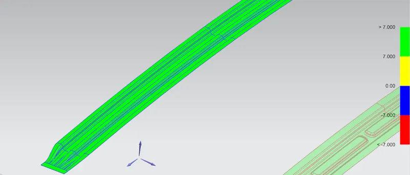
DRAFT ANALYSIS:
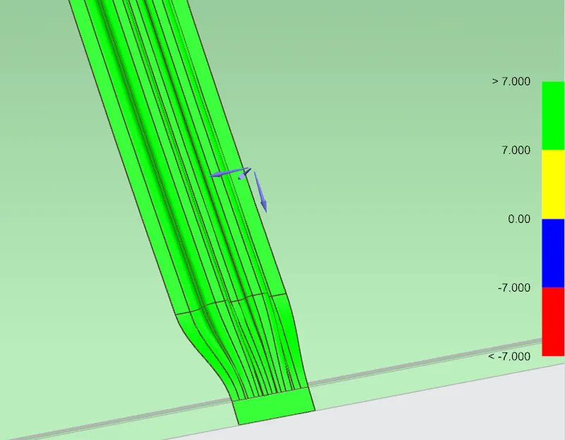
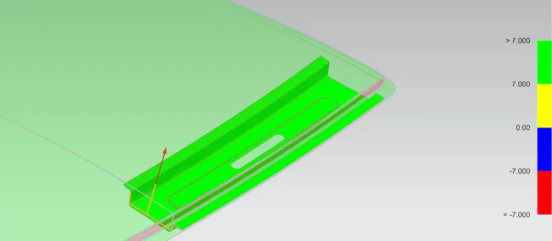
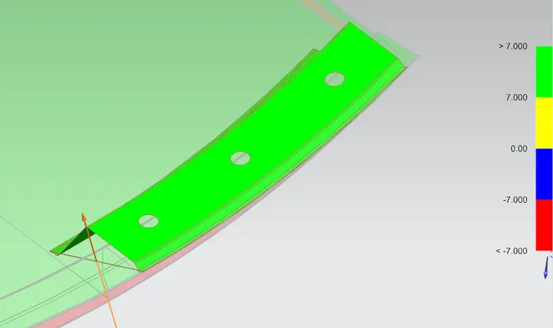
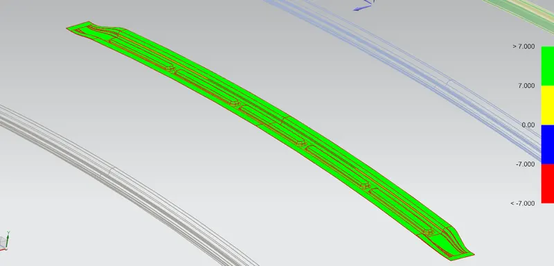
Green: Draft angle >7deg
Yellow: Positive Draft angle<7deg
- ROOF OUTER PANEL:
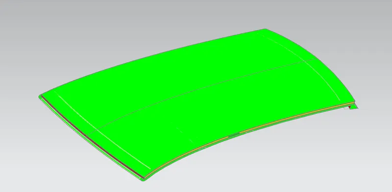
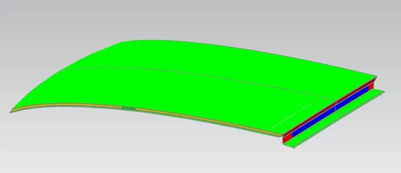
Negative Draft at front and rear is due to use of single tooling axis.
Ideally, two separate methods will be performed for achieving both the geometries. - FRONT ROOF RAIL:
- REAR ROOF RAIL:
- CENTER ROOF RAIL:
- BOW ROOF FRONT SIDE:
- BOW ROOF REAR SIDE: