Roof Design
ROOF DESIGN
- AIM :-
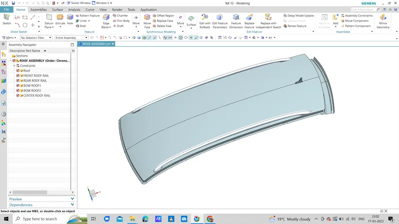
For the Given Roof styling, create an ASSEMBLY by developing the essential flanges for the outer roof and creating the reinforcements.
Provide appropriate dimensions and check for Draft analysis.
Do a curvature study on the roof and perform calculations to
determine the position of the Bow-roofs.
- INTRODUCTION:-
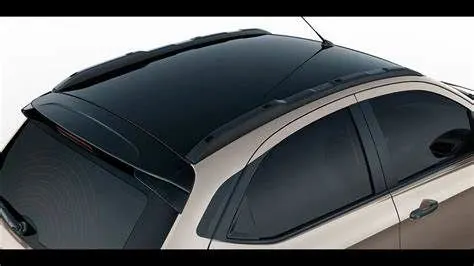
ROOF- An automobile roof or car top is the portion of an automobile that sits above the passenger compartment, protecting the vehicle occupants from sun, wind, rain, and other external elements.
The roof is a styling surface part which is fixed with the BIW body through the rails and panels inside the upper roof to provide it strength and stiffness.
- MASTER SECTIONS:-
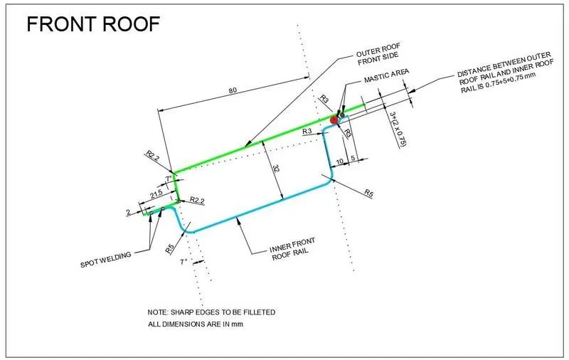
- MASTER SECTION FRONT ROOF RAIL:-
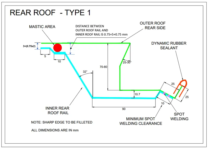
2.MASTER SECTION REAR ROOF RAIL:-
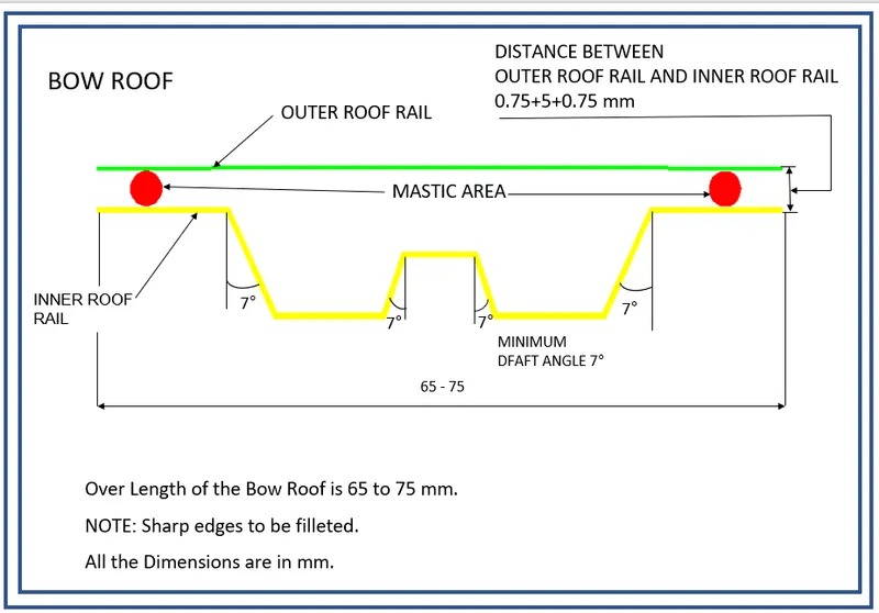
3.MASTER SECTION BOW ROOF :-
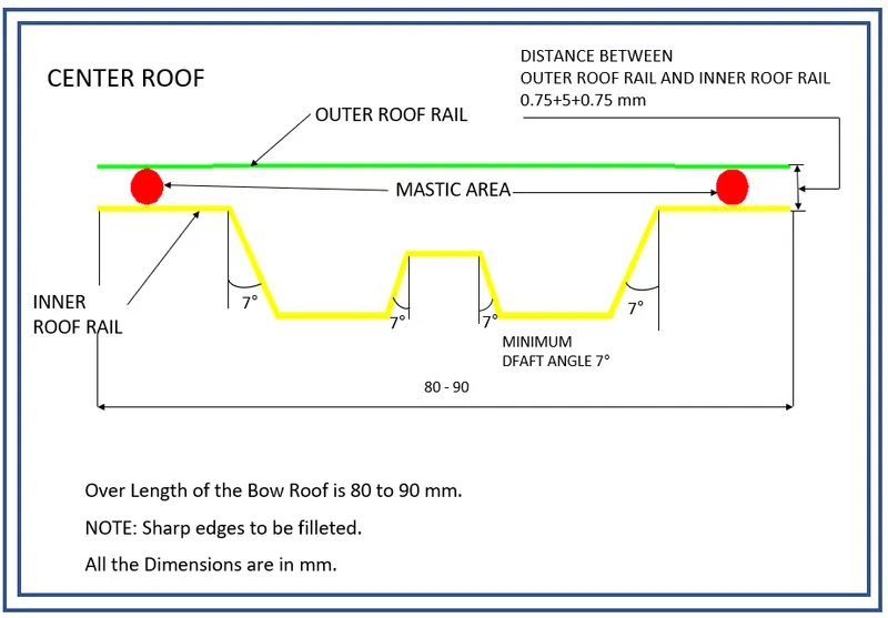
4.MASTER SECTION CENTER ROOF :-
- SOFTWARE USING :- SIEMENS NX 12.0
- COMPONENTS OF ROOF:-
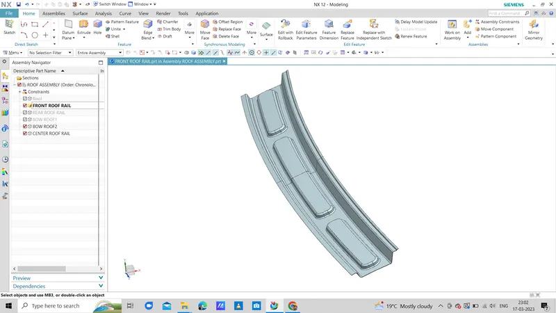
- FRONT ROOF RAIL
- REAR ROOF RAIL
- BOW ROOF
- CENTER ROOF RAIL
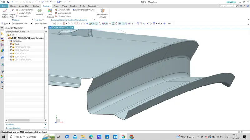
- DITCH AREA
- ROOF OUTER PANNEL:-
- DITCH AREA:-
- FRONT ROOF RAIL:-
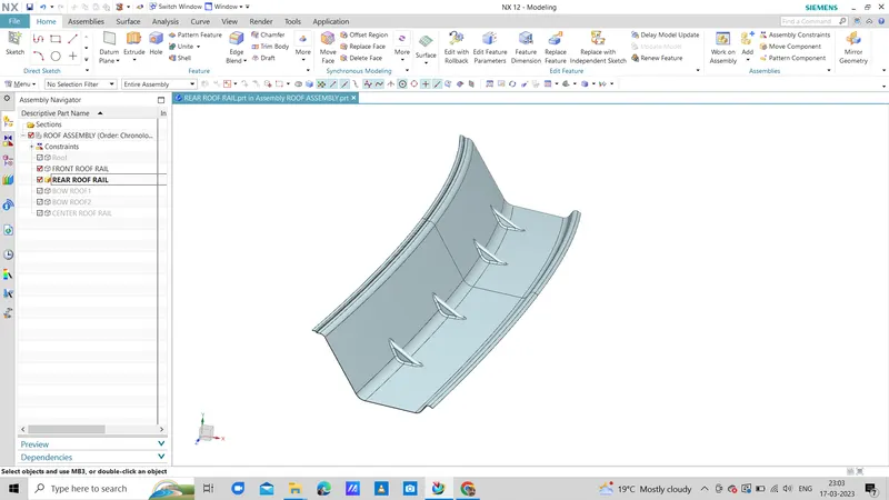
- REAR ROOF RAIL :-
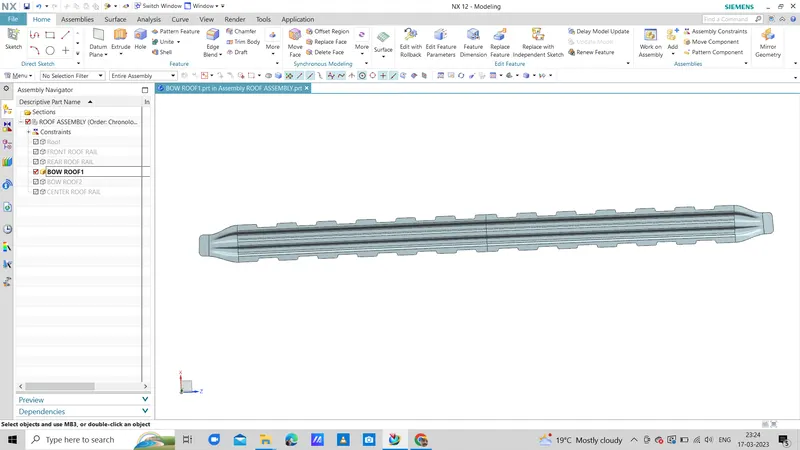
- BOW ROOF 1:-
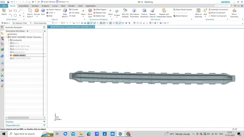
- BOW ROOF 2:-
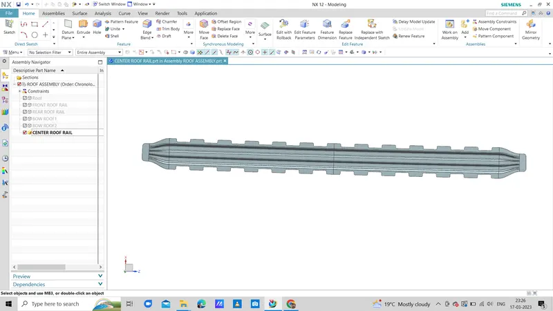
- CENTER BOW ROOF :-
- FINAL DESIGN :-
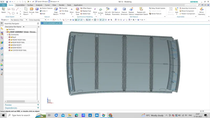
- CURVATURE STUDY CRITERIA:-
After getting the final body it has to be checked and justify that it passes the standards.
- HEAT DISTORTION CRITERIA:-
Heat distortion temperature is a temperature at which the metal softness and deform under a specific load. this study is done to check the ability of the roof to withstand high temperatue with respect to the position of the reinforcement which contributes to the increase strength.
Bow–Roof Prediction Formula
W = [1.73 x 10^(-3) x L] + [1.85 x 10^(-8) x (R^2)/t] + [ 1.10x10^(-3) x l] - 2.68
Where,
L = Roof Length in X-Direction[mm](Roof dimension in 0-Y)
R = Roof curvature
R = 2(Rx*Ry)/(Rx+Ry)
Rx = X curvature
Ry = Y curvature
t = Roof plate thickness [mm]
l = Bow Roof Span [mm]
Judgment Condition
OK< 2.7
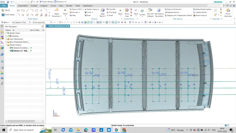
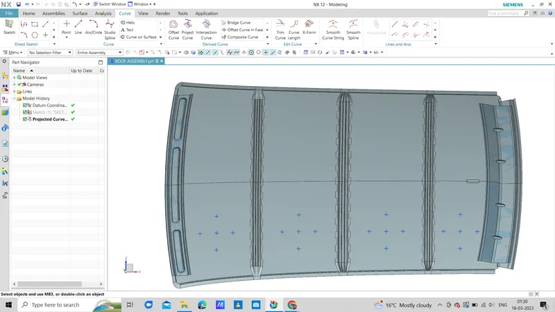
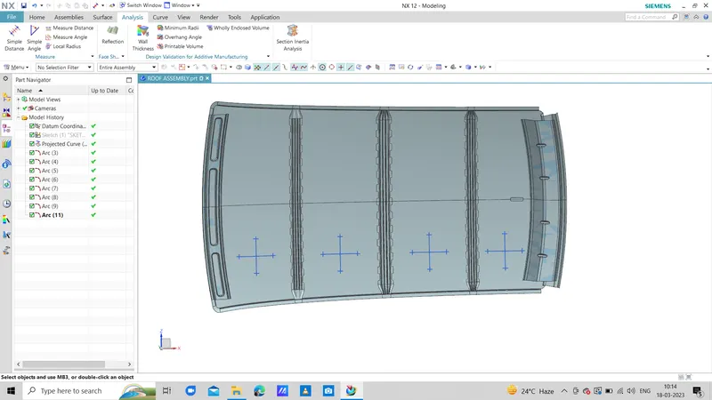
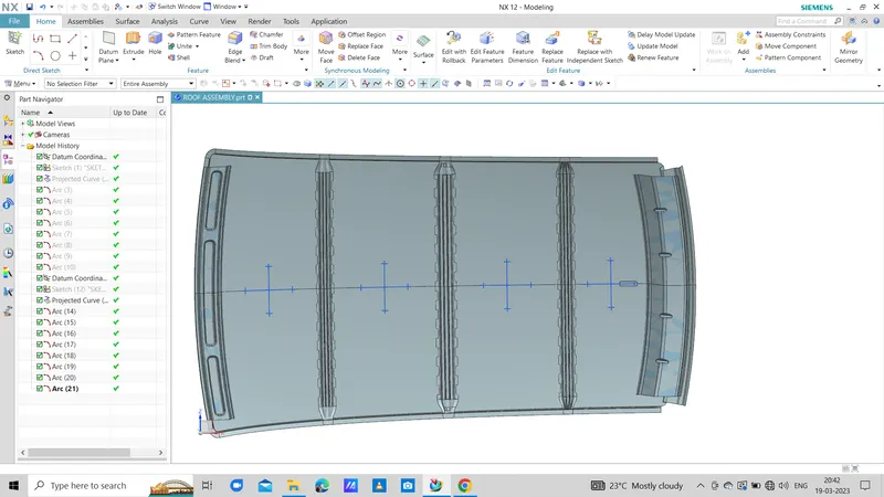
- First we need to create a sketch ,draw a horizontal line on the center of the roof
- next 300mm distance offset line from the center line
- after 100mm distance symmetric offset from 300mm line
- after creating midpoints between front roof rail- bow roof1,bow roof1-center roof, center roof-bow roof2, bow roof2- rear roof rail
- then create a line on mid pionts and 100 mm offset both side
- atlast make an intersection points on lines
- then creating three points arc on points and measured Rx &Ry values
HEAT DISTORTION CALCULATION
| BETWEEN | L | Rx | Ry | R=2*(Rx*Ry)/(Rx+Ry) | T | l | R^2/T | W | OK/NOTOK |
| FRONT ROOF RAIL -BOW ROOF1 | 2028.39 | 5734.56 | 2610.89 | 3588.13 | 0.75 | 408.90 | 1716626 | 1.57 | OK |
| BOW ROOF1-CENTER ROOF RAIL | 2028.39 | 4902.46 | 6473.83 | 5579.62 | 0.75 | 431.90 | 41509545.79 | 2.05 | OK |
| CENTER ROOF RAIL-BOW ROOF2 | 2028.39 | 3910.60 | 10919.83 | 5753.57 | 0.75 | 429.15 | 44138090.33 | 2.1 | OK |
| BOW ROOF2-REAR ROOF RAIL | 2028.39 | 3255.68 | 14743.57 | 5333.59 | 0.75 | 302.95 | 37929576.38 | 1.85 | OK |
THE DESIGN IS GOOD UNDER THE STANDARD LIMITS
2. SNOW LOAD CRITERIA:-
snow load criteria study is done to check the ability of the to withstand snowfall and bounce back to its original shape without any permanent deformation once the load is removed.
Snow Load Prediction Formula
Qr = [Iy x t2] / [α x s x [(Rx + Ry)/2]2 x 10-8]
Note: The Qr value given over here is correct. There was a typo error in the formula given in the video.
Where,
α = My x Lx2 x 10-12 , My = Y(Ly-Y)
t = Roof plate thickness [mm]
Ly = Distance between the front and rear roof Rails on the Vehicle along with 0Y[mm]
Length of Roof panel with the center point between Roof rail Front /Rear as the front and rear reference point.
Lx = Distance between the Left and Right end of the roof on the Roof BOW [mm]
The width of the roof panel is exposed on the surface.
Y = Distance front Front Roof Rail to Roof BOW[mm]
s = Distance for which Roof BOW bears divided load [mm]
s = L1/2 + L2/2
Iy = Geometrical moment of inertia of Roof BOW (Y cross-section )[mm4]
Rx = Lateral direction curvature radius of roof panel Y cross-section on Roof BOW [mm]
Roof panel curvature Radius of the Length Lx in Front view
Ry = Longitudinal Direction curvature radius of the Roof panel X cross-section on Roof BOW [mm]
Roof panel X curvature radius of length s in Side view
Judgment condition
Qr ≥ 3.1
250 ≤ s ≤ 380
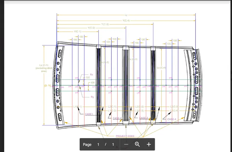
- Rx & Ry VALUES
- First we need to create a sketch ,draw a horizontal line on the center of the roof
- after 100mm distance symmetric offset from center line
- after creating midpoints between front roof rail- bow roof1,bow roof1-center roof, center roof-bow roof2, bow roof2- rear roof rail
- then create a line on mid pionts and 100 mm offset both side
- atlast make an intersection points on lines
- then creating three points arc on points and measured Rx &Ry values
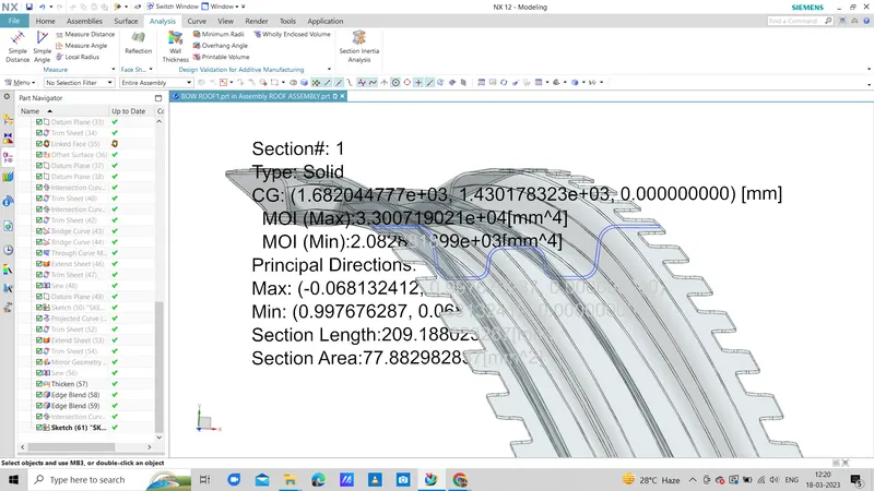
- MOMENT OF INERTIA OF BOW ROOF (Iy values)
1. BOW ROOF 1 -
MOI(min) 2.082881899e+03[mm^4]
MOI(min)2082.88
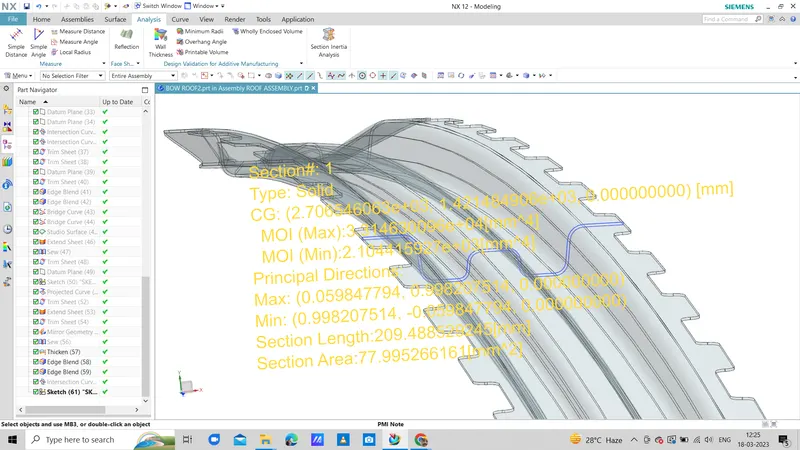
2. BOW ROOF 2 -
MOI(min) 2.104415927e+03[mm^4]
MOI(min)2104.44
3. CENTER ROOF RAIL -
MOI(min) 2.504604502e+03[mm^4]
MOI(min)2504.60
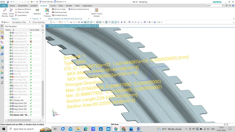
snow load calculation
| BETWEEN | ly | Lx | Ly | Y | My=Y(Ly-y) | α | L1,L2 | s=L1/2+L2/2 | Rx | Ry | t | Qr | OK/NOTOK |
| FRONT ROOF RAIL-BOW ROOF1 | 2082.88 | 1136 | 1954.07 | 499.81 | 726853.69 | 0.93 | 499.81,514.10 | 506.95 | 4488.22 | 2660.51 | 0.75 | 19.45 | OK |
| BOW ROOF1-CENTER ROOF RAIL | 2504.60 | 1084.32 | 1954.07 | 1013.92 | 953236.88 | 1.12 | 514.10,511.16 | 512.63 | 3779.14 | 6393.71 | 0.75 | 9.48 | OK |
| CENTER ROOF RAIL-BOW ROOF2 | 2104.44 | 1056.62 | 1954.07 | 1525.09 | 654233.10 | 0.73 | 511.16,428.97 | 470.06 | 4302.38 | 11501.39 | 0.75 | 5.52 | OK 3 |
| BOW ROOF2- REAR ROOF RAIL | 1954.07 | 1954.07 | 3966.57 | 16615.18 | 0.75 |
THE DESIGN IS GOOD UNDER THE JUDGMENT
- DRAFT ANALYSIS:-
IT IS done to check it the features designed clear the minimum draft 7degree for manufacturability. this type of analysis is performed based on color ranges identifying zones on the analyzed element where the deviation from the draft direction at any point corresponds to specified values.
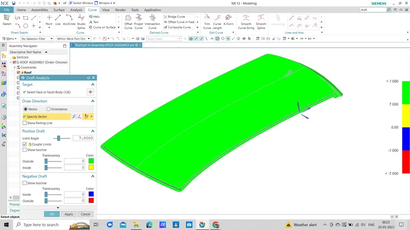
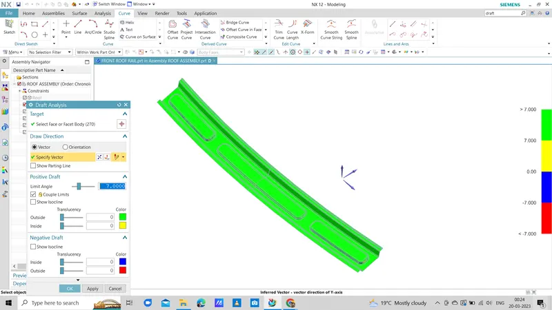
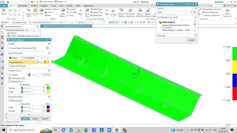
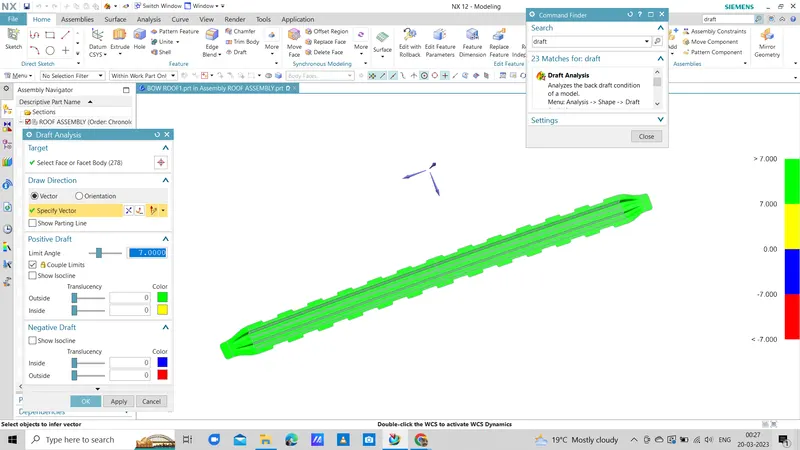
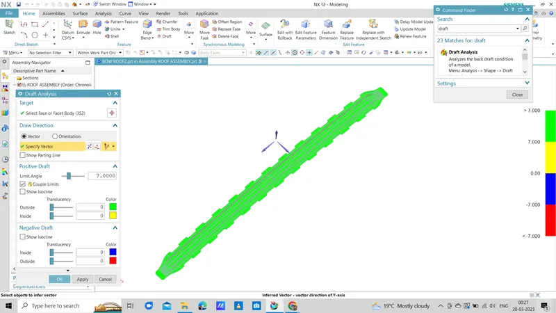
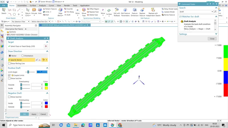
It is seen that the features designed clears the minimum draft angle which denoted in 'green'
- CONCLUSION:-
- Essential roof componnents such as bow and center rails required with flanges and reinforcements are designed.
- curvature study on roof was analysied with heat distortion and snow load calculation.
- draft analysis was done to check toolability.