Roof Design
Aim: Design of the front roof rail, rear roof rail,Center roof and bow roof for the roof of the vehicles with the help of the given skin data of the roof according to snow load condition and hear distortion criteria.
OBJECTIVES:
- Create a roof of the car by the given styling surface based on the master section provided.
- To validate the designed roof is satisfy the heat distortion criteria and snow load condition.
- To familiar about the tools and operations involved in creating the roof of the car.
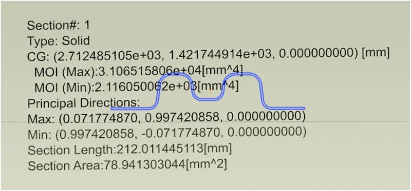
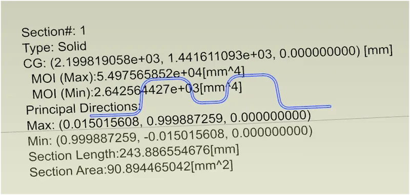
- To prepare section modulus for the bow roof 1 c centre reinforcement and bow roof 2 on the 0-Y cross section
- Draft analysis for all the part for checking the tools feasibility.
ROOF INTRODUCTION:
- The roof is an important part of an automobile as it protects the occupants from various environmental conditions like Heat, Snow, Rain, and winds.
- There are many types of the roof which differs based on the variants of the car and the region. The roof must be designed in such a way that it would able to withstand any load or impact due to accidents or objects falling on it and other environmental factors.
- So, the design done is based on the standards and design intent which makes the roof to withstand the above-said conditions. Also, other factors .Headroom, aesthetics play a role in the design.
- The roof is an assembly of many parts like Front roof rail, Bow roof, Bow roof center, and reinforcement center.
- The number of bow roofs is based on the length of the roof and sometimes even the bow roof center is avoided in cases like small cars.
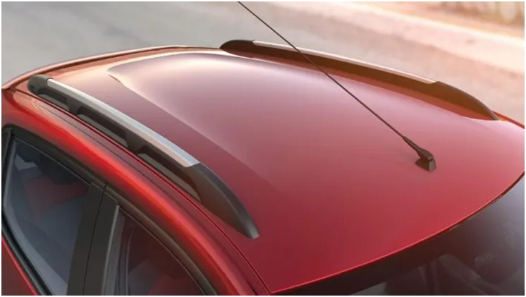
Reinforcement and its types:
If the roof is flat, it is weak and cannot able to with stand the external load like snow load, roll over and etc. so in order to increase the strength of the roof, reinforcement like front roof rail, central roof rail, rear roof rail and the bow roof are introduced and joined in the flat surface of the roof with different joining process. In general, there are four types of reinforcement are used in the hard roof top they are,
Types of roof reinforcements are as follows: -
Front roof rail reinforcement (FR)
Centre roof rail reinforcement (CR)
Bow roof 1 rail reinforcement (BR1)
Bow roof 2 rail reinforcement (BR2)
Rear rail enforcement (RR)
Joining Process:
Mastics are introduced between the roof outer panel and the reinforcements for joining. Where ever the mastics are introduced there is remarkable strength. Spot welding is also introduced to join the reinforcement and the outer panel.
Design consideration of roof:
- Visibility Criteria
- Head clearance
- Curvature study
- Heat distortion and snow load criteria
- Draft analysis
- Safety parameters
Ditch Area:
From dump solid part class A surface is extracted and ditch area are developed considering the parameter specified in the following master section.
It is the extended portion of the main roof concealed by other BIW panels and not a styling surface. Headroom clearance, visibility criteria, clearance for windshield and backdoor are some of the factors to be considered while designing the ditch area.
Flange of around 21.5mm created with the law extension command, corner relief at rear flanges and positive draft more than 7 degree considering for the drawing operation process. Overall thickness of sheet metal considers 0.75mm throughout
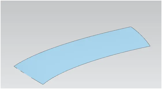
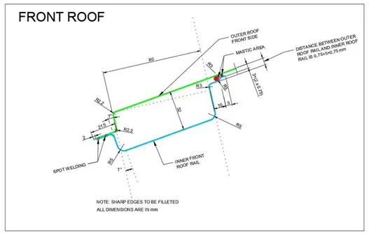
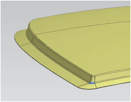
Extracted Surface Front roof master section Outer roof front ditch area
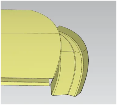
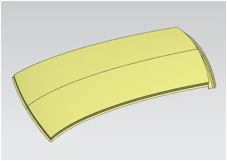
Outer roof rear ditch area Outer roof
Front Roof Rail:
- It is the support that is joined with the windshield glass, bodyside outer and the inner panels. It is usually made from body side outer scrap and therefore the thickness of the rail is 0.75 mm
- The visibility criteria and the headroom clearance of the passenger are taken into consideration for the bottommost flange.
- Windshield end and the roof end are spot welded and the other end of the front roof rail is joined with the roof using mastic sealants for increased strength.
- A draft angle of 3-5 degrees is provided for deep-drawing operation.
Front Roof Rail Images
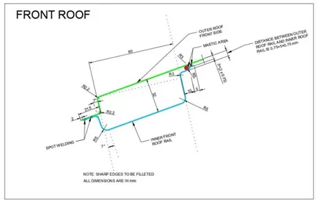
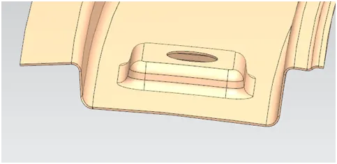
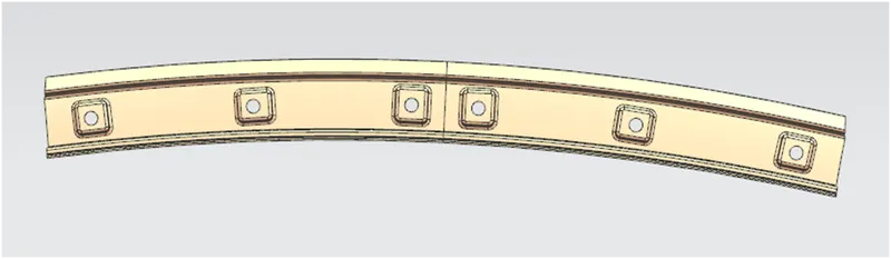
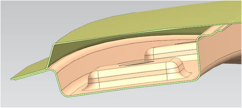
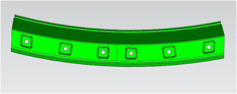
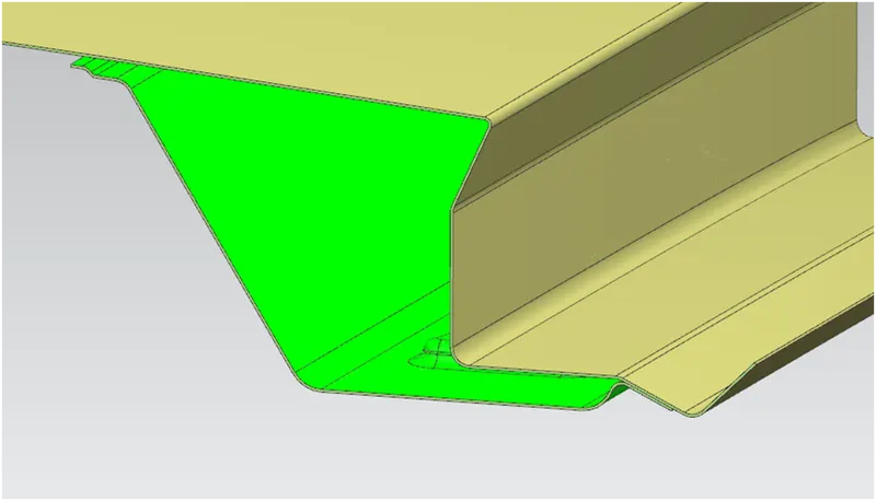
Rear Roof Rail:
- It is the support that is joined to the backdoor, the body side outer and the inner panels.
- An input from the backdoor design is also taken to accommodate the required clearance along with headroom clearance and the rear visibility criteria while designing the rear roof rail.
- Spot welds are applied at the backdoor end of the rail and the other end is joined with the roof using mastic sealants.
Rear roof rail images
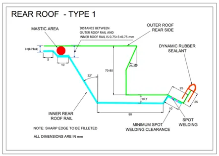
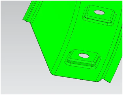
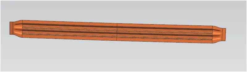
Centre Roof Rail and Bow Roofs:
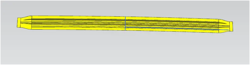
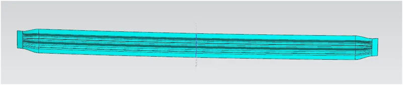
- Similar to other rail designs, we have to take into consideration the headroom clearance and the visibility criteria while designing the centre roof rail and bow roofs.
- Generally central roof rail is placed at the center of the roof which is connected to the B-pillar support structure. This central roof rail helps in the strength to the roof during the roll-over test.
- Unlike the front and rear roof rails, spot welds are not applied for joining these rails to the roof.
- Mastic sealants are introduced at both the ends instead of spot welds since centre roof rail and row roofs are fully positioned under the styling surface of the roof.
- The bow roof are given to improve the torsional stiffness and load bearing capacity of the roof structure. The number of roof presented is depends on the overall size of the roof.
- Presently in this project two bow roofs are calculated.
Centre Roof Rail and Bow Roofs Images
Bow roof 1 Bow roof 2
Center roof
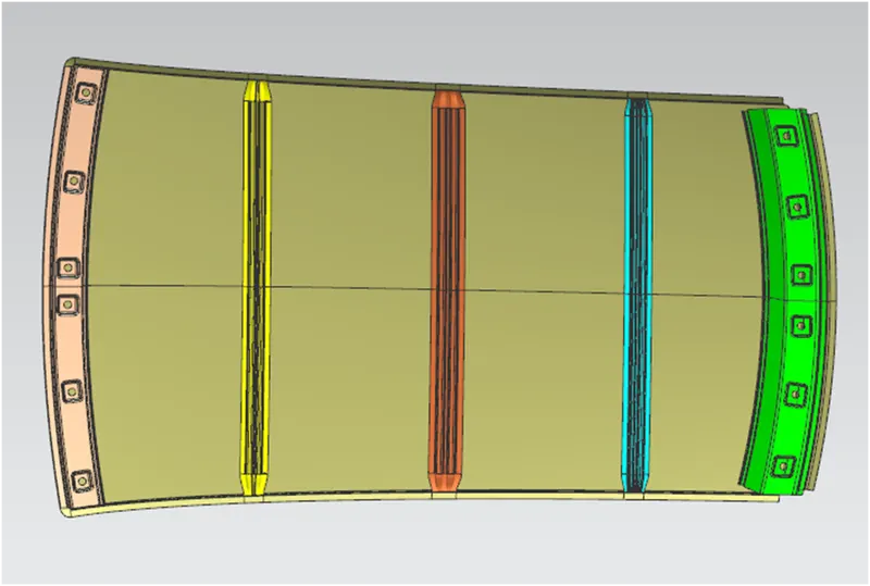
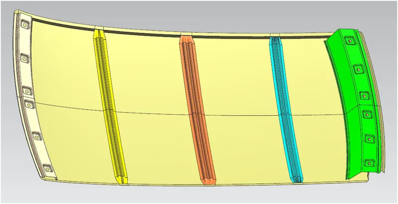
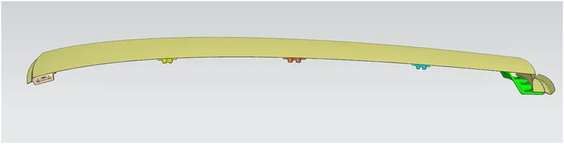
Screen shot of Different Views of Complete Roof Design:
Calculations to determine bow position:
Heat Distortion Criteria:
Heat distortion temperature is the temperature at which the metal softens and deforms under a specific load. This study is done to check the ability of the roof to withstand high temperature with respect to the positioning of the reinforcements which contribute to increased strength.
W = [1.73 x 10^(-3) x L] + [1.85 x 10^(-8) x (R^2)/t] + [ 1.10x10^(-3) x l] - 2.68
Judgment Condition : OK<2.7<NG
Where,
L = Roof Length in X-Direction[mm](Roof dimension in 0-Y)
R = Roof curvature
R = 2(Rx*Ry)/(Rx+Ry)
Rx = X curvature
Ry = Y curvature
t = Roof plate thickness [mm]
l = Bow Roof Span [mm]
Here we have to find out Rx and Ry values. To find out
- Create a sketch on Top roof and draw a horizontal line at a center.
- Then offset this line below 300mm and called it as _3y line.
- From the _3y line offset 100 mm above and below and converts all these line into reference line.
- Draw the vertical lines at the middle of each reinforcement and offset it at 100 mm both sides.
- Intersection point is created where the lines are met.
- Project there points the outer roof panel.
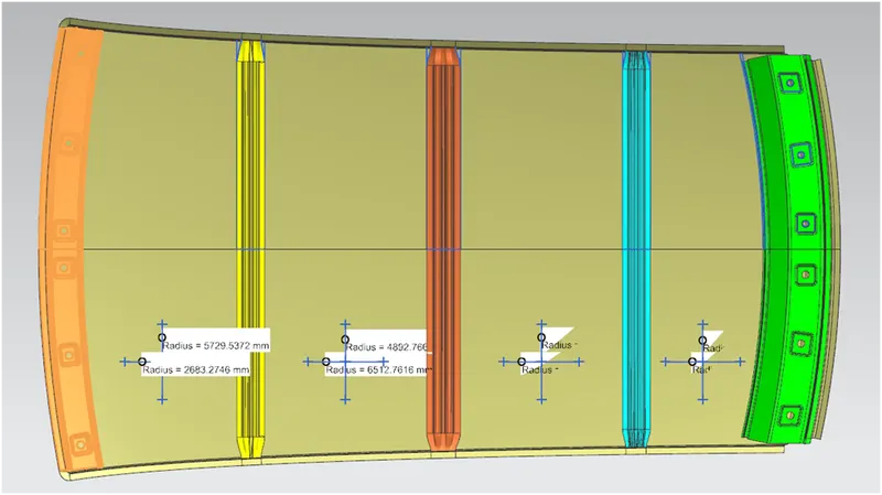
Here we have to find out L value

Here we have to find out “l”value for C1
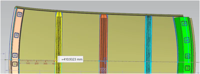
| Heat distortion calculation | ||||||||||
| SL.NO | BETWEEN RAIL | RX | Ry | R | t | I | L | R^2/t | W | Result |
| 1 | Front to Bow 1 | 5729.537 | 2683.274 | 3654.882 | 0.75 | 410.932 | 2029.422 | 17810888 | 1.612427 | OK |
| 2 | Bow1 to centre | 4892.766 | 6512.761 | 5587.715 | 0.75 | 430.775 | 2029.422 | 41630074 | 2.074909 | OK |
| 3 | Centre to Bow 2 | 3901.919 | 10964.89 | 5755.655 | 0.75 | 430.889 | 2029.422 | 44170090 | 2.122025 | OK |
| 4 | Bow2 to Rear | 3263.882 | 14689.24 | 5341.015 | 0.75 | 299.975 | 2029.422 | 38035255 | 1.864525 | OK |
Calculation Result
From the above table it can be concluded that all values of W IS within 2.7. So that current positioning of bow roof are good in state as per design and found ok.
Snow Load Criteria:
Snow load criteria study is done to check the ability of the roof to withstand snowfall and bounce back to its original shape without any permanent deformation once the load is removed.
Snow load Prediction formula
Qr = [Iy x t2] / [α x s x [(Rx + Ry)/2]2 x 10-8]
Note: The Qr value given over here is correct. There was a typo error in the formula given in the video.
Where
α = My x Lx2 x 10-12 , My = Y(Ly-Y)
Judgement condition = Qr ≥ 3.1
250 ≤ s ≤ 380
t = Roof plate thickness [mm]
Ly = Distance between the front and rear roof Rails on the Vehicle along with 0Y[mm]
Length of Roof panel with the center point between Roof rail Front /Rear as the reference point of the front and the rear.
Lx = Distance between the Left and Right end of the roof on the Roof BOW [mm]
Width of the roof panel exposed on the surface.
Y = Distance front Front Roof Rail to Roof BOW[mm]
s = Distance for which Roof BOW bears divided load [mm]
s = L1/2 + L2/2
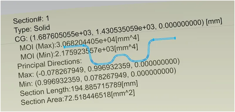
Iy = Geometrical moment of inertia of Roof BOW (Y cross-section )[mm4]
Rx = Lateral direction curvature radius of roof panel Y cross-section on Roof BOW [mm]
Roof panel curvature Radius of the Length Lx in Front view
Ry = Longitudinal Direction curvature radius of the Roof panel X cross-section on Roof BOW [mm]
Here we have to find out Rx and Ry values. To find that
- Create a sketch on Top roof and draw a horizontal line at a center.
- Offset this line to 100 mm on both sides. Convert all these line into reference line.
- Draw the vertical lines at the middle of each reinforcement and offset it at 100 mm both sides.
- Intersection point is created where the lines are met.
- Project there points the outer roof panel.
Below mentioned table value has been measured and calculated according to the projected values as shown in the figure.
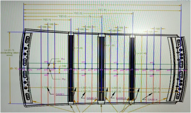
Here are some of C1 section values:
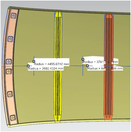
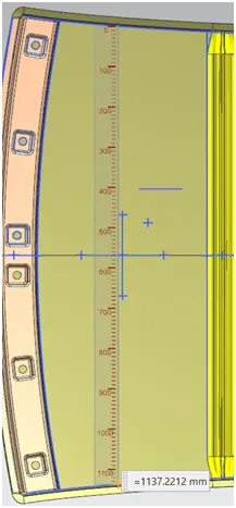

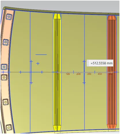
Rx and Ry values for C1 Lx value for C1 L1 value for C1 L2 value for C1
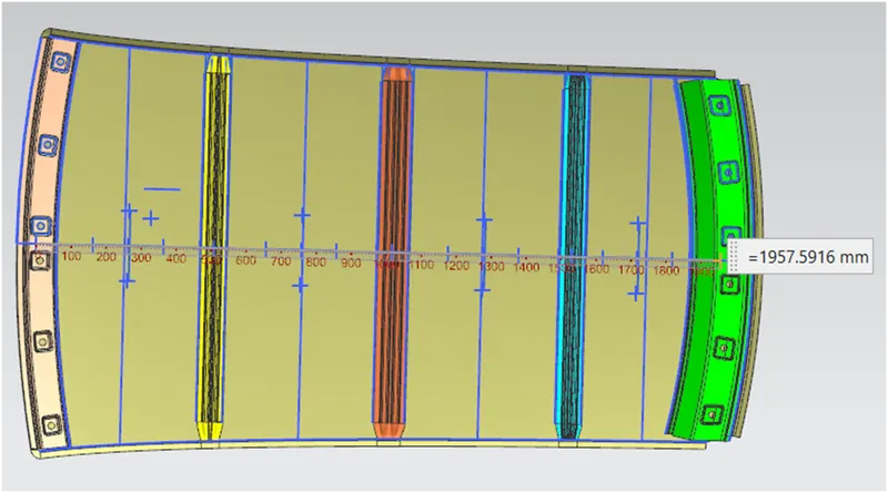
Ly value for C1
Here are some Reference images for the Master sections - These images are just to give you a brief idea about the design.
Bow roof 1 section Bow roof 2 section Centre roof section
| Snow load condition | |||||||||||||||
| s.no | Bow roof | Rx | Ry | Lx | Ly | L1 | L2 | t | Y | S | MY | a | ly | Qr | Result |
| 1 | Front to Bow1 | 4495.631 | 2680.433 | 1137.2 | 1957.591 | 505.095 | 512.558 | 0.75 | 505.095 | 508.8265 | 733648.5 | 0.948772 | 2175.9236 | 19.69346 | ok |
| 2 | Bow1 to centre | 3781.788 | 6434.979 | 1083.8 | 1957.591 | 512.558 | 512.767 | 0.75 | 1017.651 | 512.6625 | 956530.9 | 1.123563 | 2116.05 | 7.918677 | ok |
| 3 | Centre to Bow 2 | 4305.555 | 11557.86 | 1056.7 | 1957.591 | 512.767 | 427.172 | 0.75 | 1530.418 | 469.9695 | 653753.2 | 0.729991 | 2642.5644 | 6.88696 | ok |
Hence we arrived to decision after result from calculation, Qr result is acceptable.
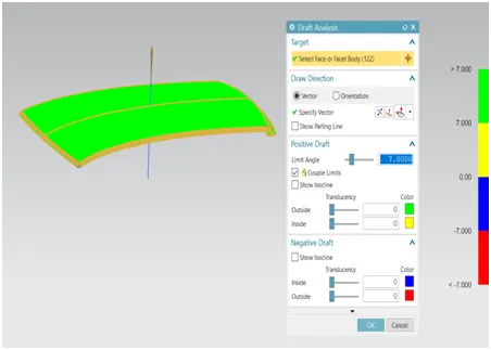
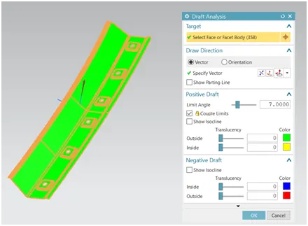
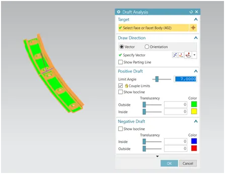
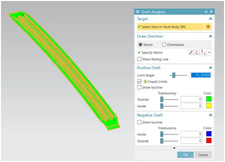
Draft analysis
The draft analysis command enables you to detect if the part has negative angle in tooling direction. This type of analysis is performed based on color ranges identifying zones on the analyzed element where the deviation from the draft direction at any point, corresponds to specified values.
Minimum draft angle of 7 degree is considered for analysis, green color infers on the parts that all face along the tooling direction has positive draft angle greater than 7 degree and passed in analysis.
Conclusion:
Thus the required reinforcement and the ditch area for the roof were designed and developed from the given styling. The curvature study was done after performing calculation for the Heat Distortion and Snow load conditions with the position criteria met for all reinforcements.
Further the section modulus study was conducted and Draft analysis were done for each reinforcement successfully.