Roof Design
AIM
- Develop the reinforcement on the given Roof surface.
- Prepare a report which includes the curvature study on the roof and section inertia analysis on the various component.
- Draft Analysis for all the parts and include the snapshot in the report.
- Calculate the heat distortion and snow load criteria based on the Bow roof prediction calculation as well as the manufacturing techniques.
CAR ROOF ASSEMBLY
INTRODUCTION
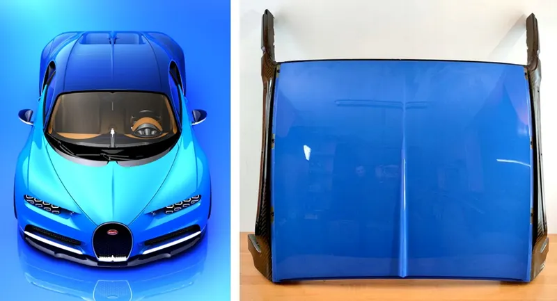
Roof is the top most part of the vehicle that sits above the passenger compartment. Under the styling surface that is seen on the outside, there are many other structures under the roof which contribute to its strength and stability. A roof assembly for a vehicle that includes a center roof panel made from a lightweight material like aluminum, a surrounding attachment flange made from a more formable and stronger material like steel, and a junction that connects the roof panel and the attachment flange together but now a days in advance technology, they also started to use the composite material to manufacture the roof.
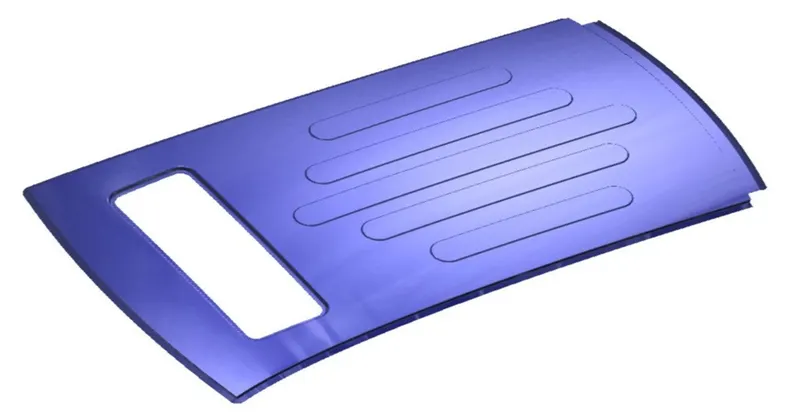
The aluminum-based roof panel may reduce the overall weight of the assembly, while the steel-based attachment flange may improve its metal forming and attachment capabilities. In order to give strength, it is provided with embosses on top of the roof.
FUNCTION
- An automobile roof protecting the vehicle occupants from sunlight, wind, rain, snow and other external elements.
- It is important for roll over kind of accidents, which the basic test performed for safety purpose.
- It offers aerodynamic support to the car when it is in motion.
TYPES OF ROOF
There are many variation on the automobile roof developed. These includes
- Roof Modules
- Hardtops and retractable hardtops
- Sunroofs
- T-tops
- Targa tops
- Vinyl roofs
1. ROOF MODULES
A roof assembly for a motor vehicle comprises a rim portion which guides a roof module towards an opening for a sliding roof cover. The rim portion is provided with a water groove formed integrally with the roof module. The roof module may have a deep-drawn outer skin made of metal, or a shaped outer skin made of synthetic material with the water groove formed on in one piece, this resulting reduction in the components required; and what is more is a reduction in tool and piece costs.
2. HARDTOPS AND RETRACTABLE HARDTOPS
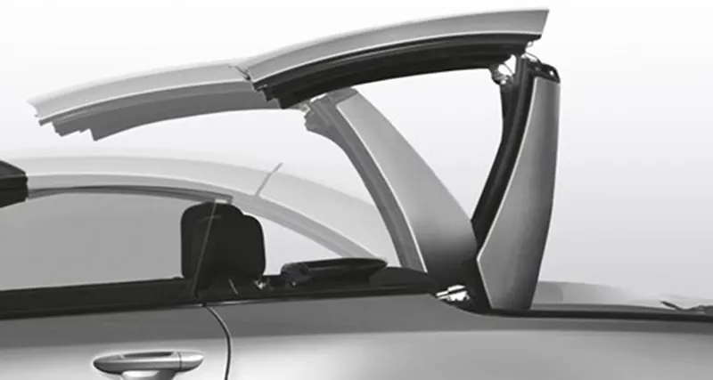
A hardtop is a rigid form of automobile roof typically metal, and integral to the design, strength, and style of the vehicle.
A retractable or removable hardtop opens up new opportunities for protection from the elements, added sound-deadening and peace of mind when you walk away from the car. The awkward packaging of some early-2000s power-retractable hardtops combined with improvements in design and construction have led many automakers to pivot back to the classic look of a cloth convertible top.

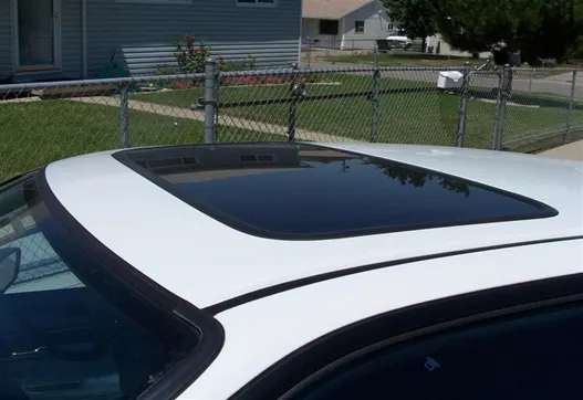
3. SUNROOFS AND MOONROOF
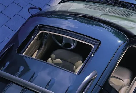
A sunroof is a movable panel that opens to uncover a window in an automobile roof, allowing light and fresh air to enter the passenger compartment. Sunroofs can be manually operated or motor driven, and are available in many shapes, sizes and styles.
In today's times, a moonroof is a roof in a car that comprises of a portion of the roof being tinted temp ered glass. Sunroofs on the other hand are referred to as a similar roof, except it can be removed completely to let the wind in and also comprises a shade to block out the glass completely in case the sun is right above.
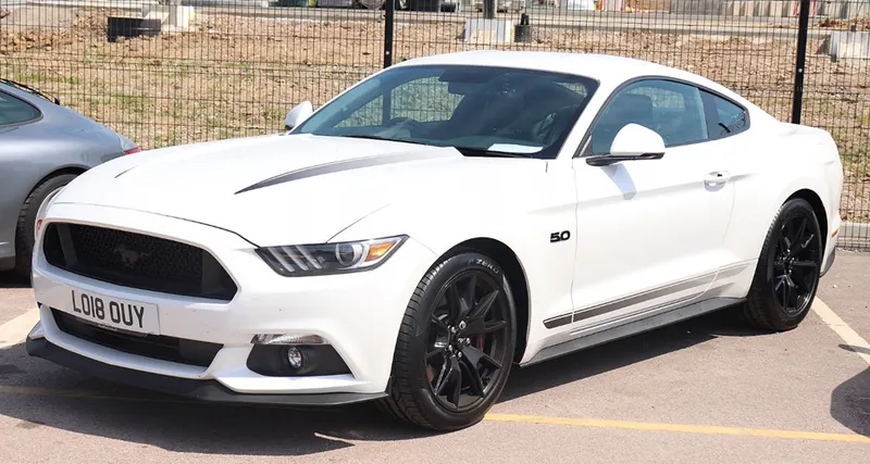
4. T-Tops
A T-top (UK: T-bar) is an automobile roof with a removable panel on each side of a rigid bar running from the center of one structural bar between pillars to the center of the next structural bar. The panels o f a traditional T-top are usually made of auto grade safety glass. The removable panel roof was patented by Gordon Buehrig on June 5, 1951. It was first used in a 1948 prototype by The American Sportscar Company or “Tasco. Ex. Buick Regal, Nissan NX, Ford Mustang,
- Targa Top
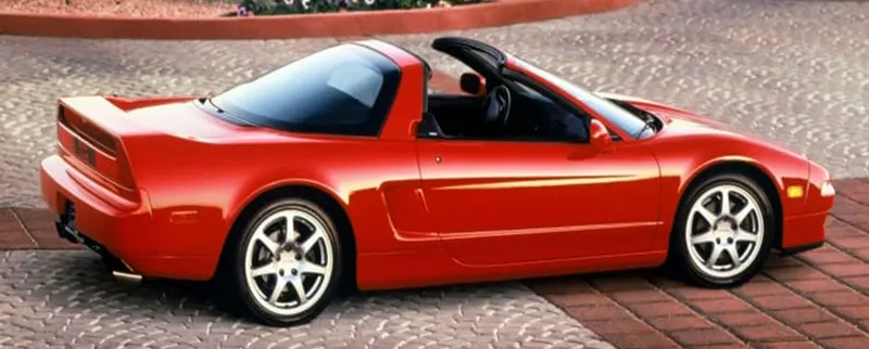
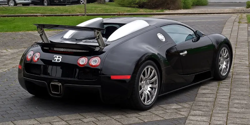
Targa top is a semi convertible car body style with a revable roof section and a full width roll behind the seats.
The rear window is normally fixed, but on some targa models, it is remavable plastic foldable window, making it a convertible-type vehicle. Any piece of normally fixed metal or trim which rises up from one side, over the roof and down other side is sometimes called a targa band. Targa bar, or a wrap over band. ex.Bugatti Veyron,Ferrari 308 GTS, ferrari 328 GTS, ford GTS-1, Honda NSX-T etc.
- VINYL ROOF
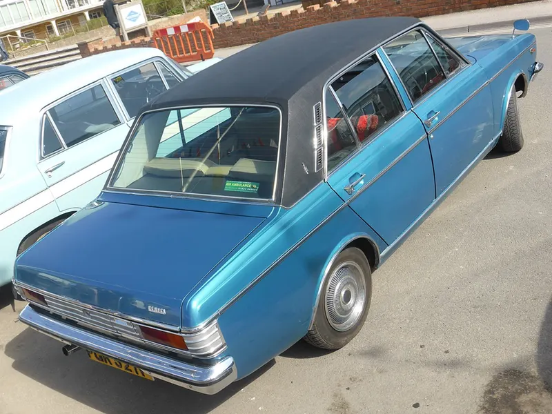
This covering was originally designed to give the appearance of a convertible to models with a fixed roof and eventually evolved into a styling statement in its own right. Vinyl roofs were most popular in the American market, and they are considered one of the period hallmarks of the 1970s domestic cars. Vinyl roofs were also popular on European- (especially UK-) and Japanese-built cars during the 1970s, and tended to be applied to sporting or luxury trim versions of standard saloon (sedan) models. Ex 1976 Toyota Corona Mark II, Lincoln Town, Lincoln Mark VI etc.
DESIGNING PROCESS
1. COLLECT INFORMATION
- Collecting all the information for design of roof from styling team.
- Taking information from the master section.
- Collect all the basic information about assembly of roof.
2. THICKNESS OF ROOF
- Thickness of the roof is about of 0.75mm, which is taken after all consideration.
- thickness of front roof rail, bow roof one, center roof, bow roof two and rear roof rail is also 0.75mm is taken.
3. MASTER SECTION
The master section is generally created is based on requirement from marketability team and this is done by taking all consideration that we saw before. The master section is predefined. The master section is little bit changes although same for all.To design the roof and its reinforcement, master section is very important.
4. MASTIC SEALANT
- Mastic sealant is used to join the roof to the reinforcement applied on the roof.
- Provided a gap of 5mm for the mastic sealant.
5. SPOT WELDING
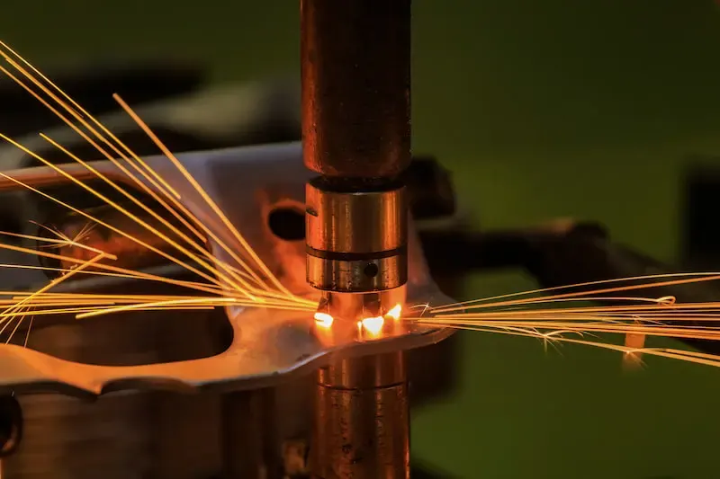
- Spot welding (or resistance spot welding) is a type of electric resistance welding used to weld various sheet metal products, through a process in which contacting metal surface points are joined by the heat obtained from resistance to electric current
- Spot welding is done in one edges of front roof to the roof outer and on the rear roof rail to the roof outer.
- There have no gap given for the spot welding.
6. HEAD ROOM CLEARANCE
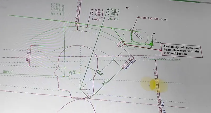
- Head room clearance is most important part for the desin of roof.
- Headroom is measured as the distance from a car’s roof to its seat bottom.
- Headroom clearance is depend upon the height of the people. generally head room clearance is considered as per the height taken of 6ft.
- The clearance is about of 85mm from the head line.
- Head room clearance is depend upon project top project and region to region
7. MAXIMUM VISIBILITY CRITERIA
- Maximum visibility criteria allow the visibility of the thing.
- While creating front roof rail and rear roof rail, the maximum visibility area should be considered.
- Generally 45degree is taken for the maximum visibility.
- To drive the car in proper way and with safety, visibility criteria is most important.
DESIGNING OF OUTER ROOF
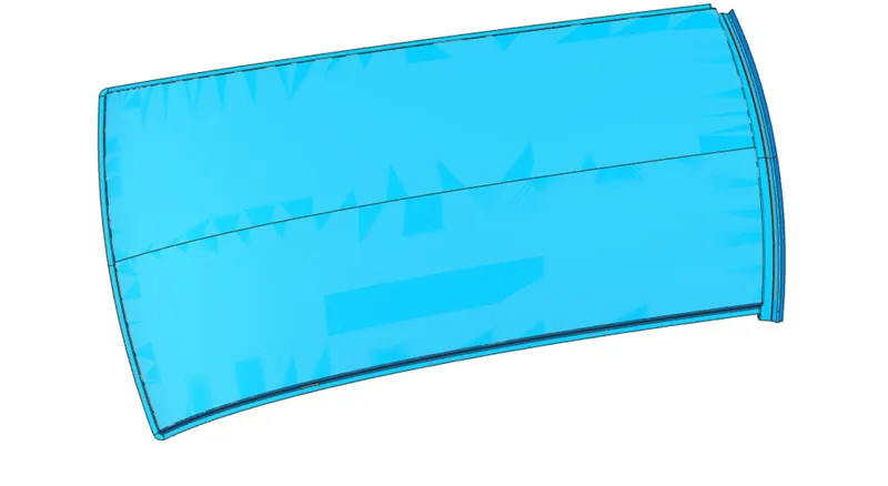
Outer roof is the outer part of the roof or we can say that it is top most part of the vehicle, which comes in contact with the sun rays, rain, snow, wind and other external effect. So, the designing of the outer roof is most important. The wind shield is attached on outer roof (front roof side)
On the rear side of the outer roof there have the different type of section is provided because the back door is mountain on the rear side of roof outer. And also hinge is placed there and seal is applied on the rear side of the outer roof.
Thickness of the outer roof is 0.75mm.
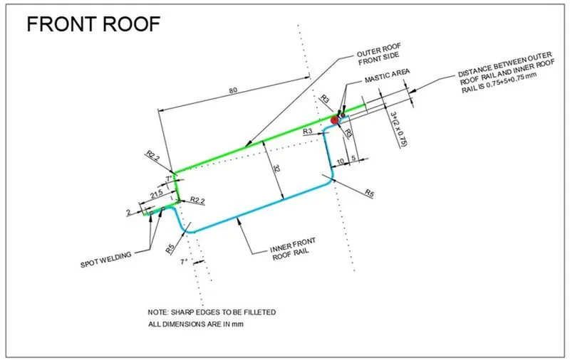
OUTER ROOF (FRONT ROOF RAIL SIDE)
- Extract the given body to develop the outer roof.
- Untrimmed the surface to remove holes.
- Trim the extra surface by taking reference to the datum plane and take half of the portion for develop the design.
- One end edges of front roof side on outer roof is taken as styling point.
- Apply the law extension command of about of 7 degree on front side roof to give the maximum visibility criteria for the driver.
- The height of law extension is depend upon Wind shield gap, rubber pasted gap and sealant running gap which is provided here.
- Offset the outer surface in inward direction and apply the trim and extend on offset surface and law extension surface.
- Extend the offset surface for maintaining the distance of 21.5mm. This distance is taken to provide the gap Wind shield gap, rubber pasted gap, mould etc.
- All the dimension is taken here as minimum most requirement.
- Apply the radius on all the corner to avoid the sharp edges.
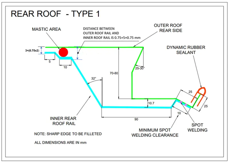
OUTER ROOF (REAR ROOF RAIL SIDE)
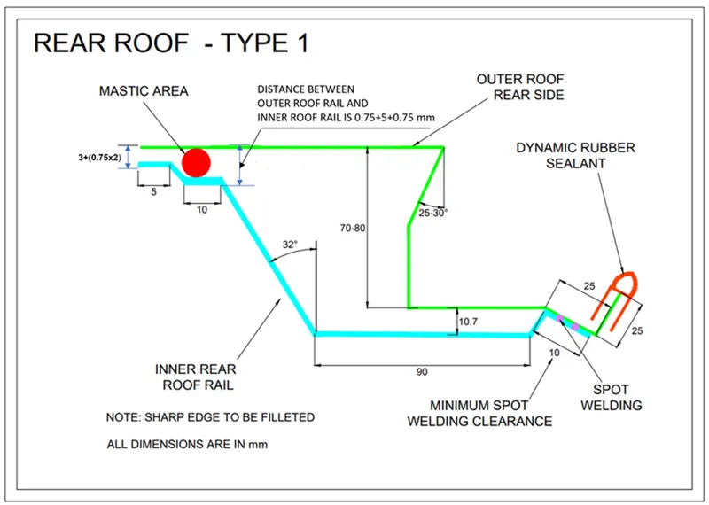
- Apply law extension on the rear side of outer roof of angle of 25-30 degree, again apply law extension and maintain the both law extension vertical distance about of 70-80mm.
- Offset the outer surface in between of 70-80mm and apply trim and extend on law extension and offset surface.
- This distance is provided for hinge section and head room clearance.
- Do the feature of law extension again for the distance of 25mm in some angle for two time.
- The angle and this type structure is create for provided the space to mount the back door and for dynamic rubber sealant.
- Apply the radius on all the corner to avoid the sharp edges.
DIFFERENT REINFORCEMENT IN A ROOF PANEL
Roof is not just a single panel of 0.75 mm thickness, it is also a panel which have multiple reinforcement that provide support and strength to the roof component. The roof panel is attached to the BIW of the car with the help of front and rear roof rail. This attachment is done with the help of mastic sealants. There are 3 primary roof rails in a car the front, the center, and the rear, while additional roof rails are called Bow roof rails. The number of bow roof rails depends on the size of the roof. Longer the roof, more the number of bow roof rails. Other dimensions like strength and material are governed by the factors like headroom, overall space, visibility, ergonomics and the rules and regulation of the states where it is sold. Some roofs have a window on them and are called sunroofs, while convertibles have special mechanisms that allow the roof to be retracted and be stowed away through a wide array of methods depending on the design.
- FRONT ROOF RAIL
- BOW ROOF ONE
- CENTER ROOF RAIL
- BOW ROOF TWO
- REAR ROOF RAIL
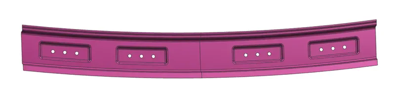
1. FRONT ROOF RAIL
Front and rear roof rails are cut a part as there will be mounting of A and C pillars. Front roof rails is the one which is joined with the wind shield glass and body side outer. Front roof has certain feature in it, which will be supporting the bracket map lamp and the room lamp. The visibility criteria and the head room clearances of the passenger are taken into consideration for the bottom flange.
- Thickness of the front roof rail is taken 0.75mm towards the outer roof.
- Mastic is used to join the outer roof and inner roof on one side.
- In other side spot welding is used to join the inner roof and outer roof.
DESIGNING OF FRONT ROOF RAIL
- Take the extract half portion for the reference through wave geometry linker.
- Offset the outer roof in 32mm distance.
- Extend the sheet on front side and apply the law extension at an angle of 7 degree.
- Offset the front side of outer roof to a distance of 0.75+0.75 mm(thickness of outer roof
- +thickness of front roof rain) and apply trim and extend on offset surface and law extension surface.
- Maintain the distance of surface about of 2 mm less than the outer roof surface.
- On the other side edges apply law extension at some angle.
- Offset outer surface to a distance of 6.5mm and apply trim and extend on offset surface and law extension surface. This distance is provided for mastic sealant.
- Maintain the distance of 10mm in horizontal side of offset surface. Apply the law extension at some angle.
- Offset the outer surface to a distance of 4.5mm and apply trim and extend on law extension surface and offset surface.
- Maintain the distance of 5mm in horizontal side of offset surface.
- Remove all the sharp edges by applying the blend radius on corners.
- Create emboss of flat surface by taking reference of datum plane.
- Sew all the surface and apply mirror geometry through datum plane.
- At last sew both surface and apply the thickness.
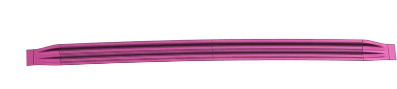
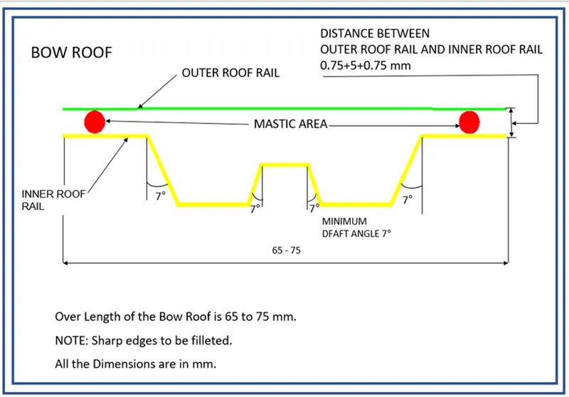
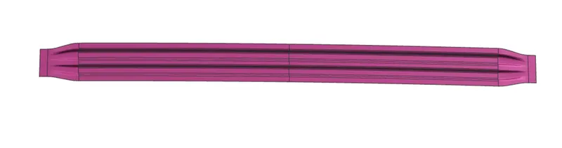
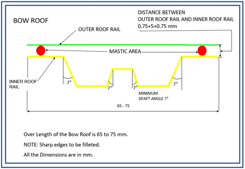
2. BOW ROOF ONE
Bow roof rail reinforcement is provided for the strength of the outer roof. It is placed in between of front roof rail and center roof rail. The design is created after consideration of head room clearance. Mastic sealant used to join the outer roof and bow roof one. Telescoping roof bow mounting bracket coupled to one end of the first roof bow member panel and the second end being attached to the roof bow member. Thickness of the front roof rail is taken 0.75mm towards the outer roof.
DESIGNING OF FRONT ROOF RAIL
- Take the extract half portion for the reference through wave geometry linker.
- Create the datum plane on curve of outer roof at desired distance.
- Draw the line by applying the intersection curve outer surface as taking reference of the datum plane.
- Offset the outer surface at 6.5mm distance in inward direction and hide the outer reference surface.
- Offset the curve at some distance and trim the offset sheet from one side.
- Again offset the previous offset sheet at some distance.
- Apply law extension command at angle of 7 degree and apply trim and extend command.
- Make the Bow roof structure as per master section by applying the law extension and trim and extend command. Also maintain the distance of bow roof in between of 65-75mm.
- Remove all the sharp edges by applying the blend radius on corners.
- Offset the outer roof edge surface to a distance of 1.5mm in inward direction. Create two datum plane on the bow roof and trim the offset sheet by taking reference of these two datum plane.
- Trim the bow roof at some distance by taking reference of datum plane, which is created on X direction at some distance.
- Apply the bridge curve in between of bow roof and trim surface and joined them by through curved mesh.
- Sew all the surface and apply mirror geometry through datum plane.
- At last sew both surface and apply the thickness.
3. CENTER ROOF RAIL
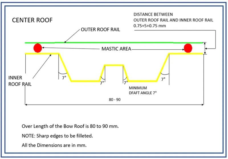
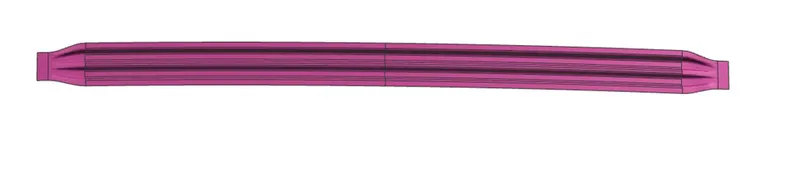
Center roof rail reinforcement is provided for the strength of the outer roof. It is placed in between of bow roof one and bow roof two. The design is created after consideration of head room clearance. Mastic sealant used to join the outer roof and center roof. . Thickness of the front roof rail is taken 0.75mm towards the outer roof.
DESIGNING OF CENTER ROOF RAIL
- Take the extract half portion for the reference through wave geometry linker.
- Create the datum plane on curve of outer roof at desired distance.
- Draw the line by applying the intersection curve outer surface as taking reference of the datum plane.
- Offset the outer surface at 6.5mm distance in inward direction and hide the outer reference surface.
- Offset the curve at some distance and trim the offset sheet from one side.
- Again offset the previous offset sheet at some distance.
- Apply law extension command at angle of 7 degree and apply trim and extend command.
- Make the center roof structure as per master section by applying the law extension and trim and extend command. Also maintain the distance of center roof in between of 80-90mm.
- Remove all the sharp edges by applying the blend radius on corners.
- Offset the outer roof edge surface to a distance of 1.5mm in inward direction. Create two datum plane on the bow roof and trim the offset sheet by taking reference of these two datum plane.
- Trim the bow roof at some distance by taking reference of datum plane, which is created on X direction at some distance
- Apply the bridge curve in between of bow roof and trim surface and joined them by through curved mesh.
- Sew all the surface and apply mirror geometry through datum plane.
- At last sew both surface and apply the thickness.
4. BOW ROOF TWO
Bow roof rail reinforcement is provided for the strength of the outer roof. It is placed in between of rear roof rail and center roof rail. The design is created after consideration of head room clearance and visibility criteria. Mastic sealant used to join the outer roof and bow roof two. Telescoping roof bow mounting bracket coupled to one end of the second roof bow member panel and the second end being attached to the roof bow member. Thickness of the front roof rail is taken 0.75mm towards the outer roof.
DESIGNING OF BOW ROOF TWO
- Take the extract half portion for the reference through wave geometry linker.
- Create the datum plane on curve of outer roof at desired distance.
- Draw the line by applying the intersection curve outer surface as taking reference of the datum plane.
- Offset the outer surface at 6.5mm distance in inward direction and hide the outer reference surface.
- Offset the curve at some distance and trim the offset sheet from one side.
- Again offset the previous offset sheet at some distance.
- Apply law extension command at angle of 7 degree and apply trim and extend command.
- Make the Bow roof structure as per master section by applying the law extension and trim and extend command. Also maintain the distance of bow roof in between of 65-75mm.
- Remove all the sharp edges by applying the blend radius on corners.
- Offset the outer roof edge surface to a distance of 1.5mm in inward direction. Create two datum plane on the bow roof and trim the offset sheet by taking reference of these two datum plane.
- Trim the bow roof at some distance by taking reference of datum plane, which is created on X direction at some distance.
- Apply the bridge curve in between of bow roof and trim surface and joined them by through curved mesh.
- Sew all the surface and apply mirror geometry through datum plane.
- At last sew both surface and apply the thickness.
5. REAR ROOF RAIL
Rear roof rail is sit on rear most part of the outer roof surface. Rear roof rail is the one which joined with the back door. The hinge mechanism is also mounted on the rear roof side for the door of the boot. The visibility criteria and the head room clearances of the passenger are taken into consideration for the bottom flange. A thickness of the rear roof rail is 0.75mm. The dynamic rubber sealant is also provide on the rear roof rail.
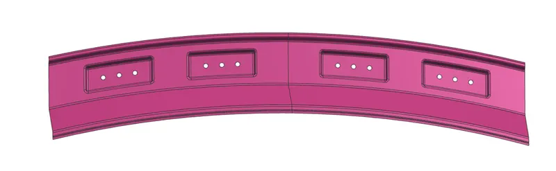
DESIGNING OF REAR ROOF
- Take the extract half portion for the reference through wave geometry linker.
- Create the datum plane on curve of outer roof at desired distance.
- Draw the line by applying the intersection curve outer surface as taking reference of the datum plane.
- Offset the outer roof in distance of 70-80mm, 10.7mm, 6.5mm and 4.5mm and 1.5mm.
- Trim sheet wherever required and also extend sheet as per consideration.
- Apply the law extension wherever required.
- Apply trim and extend command and maintain all the distance as per master section.
- After completing the rear roof rail, sew all surface.
- Apply mirror geometry through datum plane.
- At last sew both surface and apply the thickness.
ANNALYSIS ON ROOF
- DRAFT ANALYSIS
- ROOF CRUST TEST
- SECTION MOMENT OF INERTIA
- HEAT DISTORTION
- SNOW LOAD CRITERIA
A. DRAFT ANALYSIS
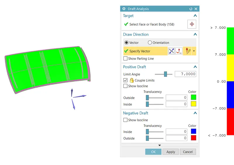
The draft analysis technique is used to analyze our part model, whether it is manufactured on the proper draft angle applied. A Draft Angle describes the amount of taper for molded or cast parts perpendicular to the parting line or vertical axis.It also helps to find the negative draft present in the component which can cause difficulty in manufacture ability.
No parts can be ejected from the tool if it is having a straight 90-degree profile from its base surface. A small draft angle is provided to each and every area of the component in order to get easy removal of the component from the tool.
1. OUTER ROOF
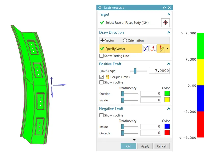
Applied the draft analysis on roof outer at angle of 7 degree. For that click on draft analysis, then click on face or facet body option and select the outer roof body. Enter the value of limit angle then select specify vector. Select the direction.
- The green and yellow portion is shown the part is created in proper limit angle and it is satisfied.
- The blue and red part is shown that the part is created not in proper limit angle and satisfied or not good.
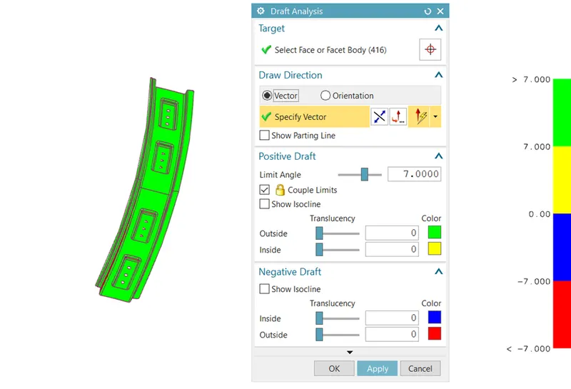
2. FRONT ROOF RAIL
Applied the draft analysis on front roof rail at angle of 7 degree. For that click on draft analysis, then click on face or facet body option and select the front roof rail. Enter the value of limit angle then select specify vector. Select the direction.
- The green and yellow portion is shown the part is created in proper limit angle and it is satisfied.
- The blue and red part is shown that the part is created not in proper limit angle and satisfied or not good.
3. BOW ROOF ONE
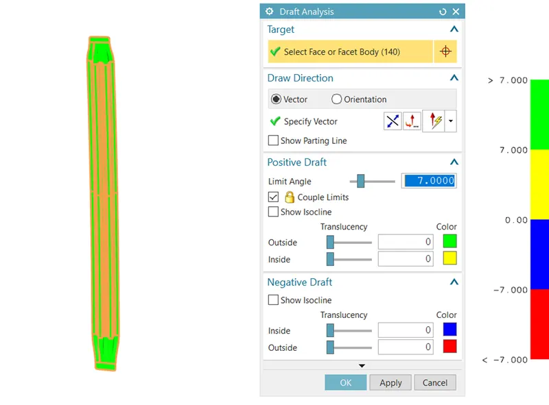
Applied the draft analysis on bow roof one at angle of 7 degree. For that click on draft analysis, then click on face or facet body option and select the bow roof one. Enter the value of limit angle then select specify vector. Select the direction.
- The green and yellow portion is shown the part is created in proper limit angle and it is satisfied.
- The blue and red part is shown that the part is created not in proper limit angle and satisfied or not good.
4. CENTER ROOF RAIL
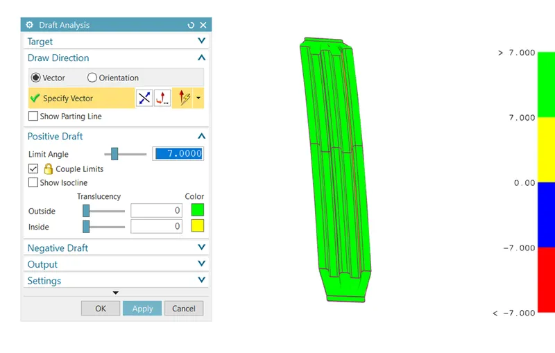
Applied the draft analysis on center roof rail at angle of 7 degree. For that click on draft analysis, then click on face or facet body option and select the center roof rail. Enter the value of limit angle then select specify vector. Select the direction.
- The green and yellow portion is shown the part is created in proper limit angle and it is satisfied.
- The blue and red part is shown that the part is created not in proper limit angle and satisfied or not good.
5. BOW ROOF TWO
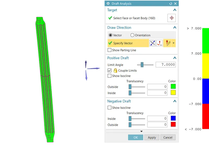
Applied the draft analysis on bow roof two at angle of 7 degree. For that click on draft analysis, then click on face or facet body option and select the bow roof two. Enter the value of limit angle then select specify vector. Select the direction.
- The green and yellow portion is shown the part is created in proper limit angle and it is satisfied.
- The blue and red part is shown that the part is created not in proper limit angle and satisfied or not good.
6. REAR ROOF RAIL
Applied the draft analysis on Rear Roof Rail at angle of 7 degree. For that click on draft analysis, then click on face or facet body option and select the Rear Roof Rail. Enter the value of limit angle then select specify vector. Select the direction.
- The green and yellow portion is shown the part is created in proper limit angle and it is satisfied.
- The blue and red part is shown that the part is created not in proper limit angle and satisfied or not good.
B. ROOF CRUST TEST
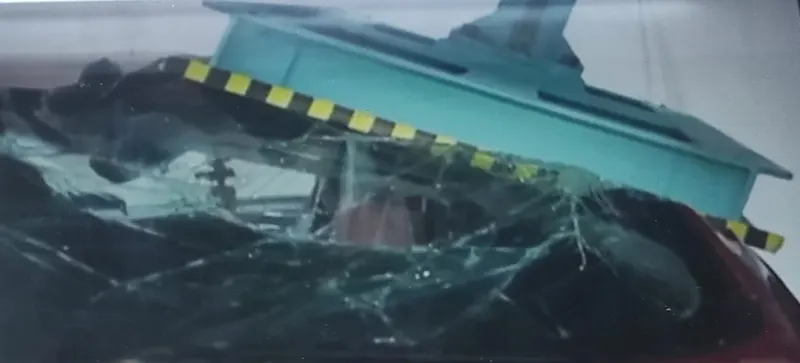
Roof crust test is done after the part is manufactured in physical condition. When the car roof is manufactured then it is tested whether the roof is right or wrong. Rollover is very important test of roof, in which the Roof crust test is done. There have many accident is happened on the highway. The institute of highway analyzing this they fixed some regulation to perform the test. They also give the rating for how fast the car reform to the original shape and how to deep the protrusion after the collision.
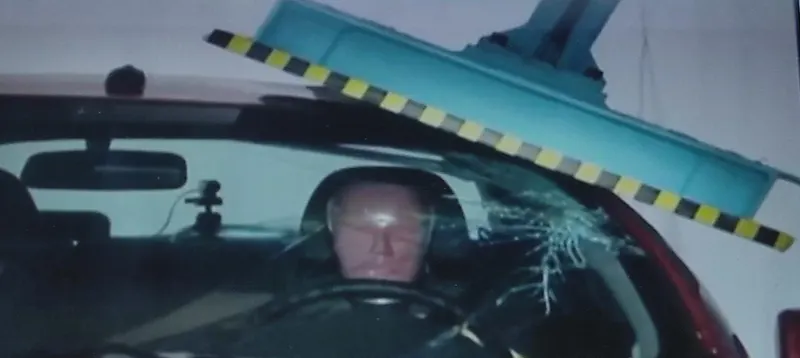
- This test is done after closing all the window and door of the car.
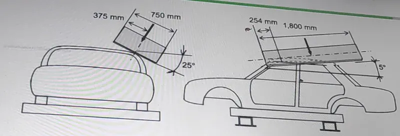
- The load is applied on the BIW at some shape of position.
- From the front rail to rear rail the load is applied in angle of 5 degree in 1800mm.
- From the flatness of surface, load is given at angle of 25 degree in 750mm.
Analysis
- Create the load displacement graph.
- Create the displacement time and loading speed time graph.
- Recording of the deformation condition using the measuring result.
- Take the photograph of deformation condition for record.
RESULTS
- By analyzing all the section and graph, if the displacement goes above the requirement level, then we have to increase the bow roof thickness or find some other solution to give the strength to the roof.
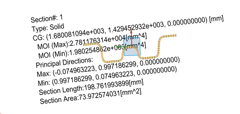
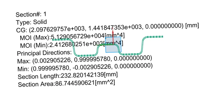
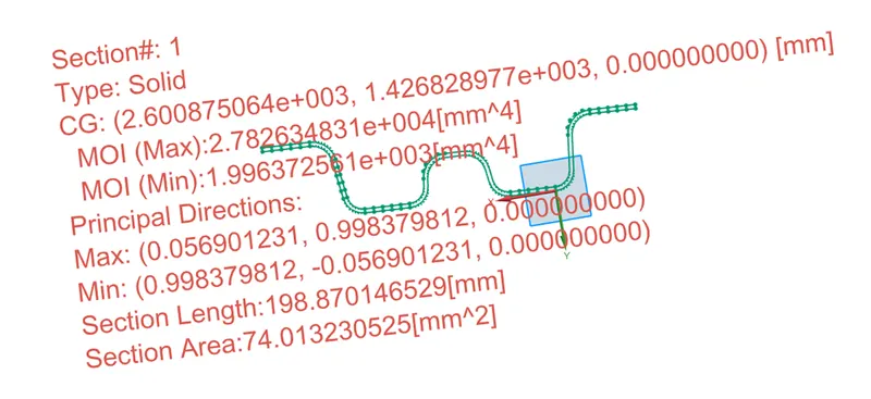
C. SECTION MOMENT OF INERTIA
Area moment of inertia also known as second area moment or 2nd moment of area is a property of a two-dimensional plane shape where it shows how its points are dispersed in an arbitrary axis in the cross-sectional plane. This property basically characterizes the deflection of the plane shape under some load.
Area moment of inertia is usually denoted by ‘I’ for an axis in a plane. The dimension unit of second area moment is Length to the power of four which is given as L4. Section moment of Inertia is done on the bow roof and center roof rail to find the minimum moment of inertia.
1. BOW ROOF ONE
2. CENTER ROOF
3. BOW ROOF TWO
C. HEAT DISTORTION
Heat Distortion is the temperature at which the metal softens and deforms under a specific load. Roof of a car is probably the only component which is exposed to sun for almost all the time. So, this study is done to check the ability of the roof to withstand high temperature with respect to the positioning of the reinforcements which contributes to increase the strength.

PURPOSE OF HEAT DISTORTION CALCULATION
Those country where the impact of heat is more, the radiation of sun is impact on the outer roof surface and the surface is heated and due to the heat the roof surface is thermally expanded. Thermal expansion is the tendency of matter to change in volume in response to temperature alterations. When a substance is heated, its particles move more and thus maintain a greater average separation and it is also possibility of hanging of the car roof. Due to heat, the surface is converted from solid stage to semi solid stage and the area of surface is sagging due to this and can be split the bond.
So, heat distortion is done to find, whether the area of surface is capable to withstand and which area is not capable. If the area is not capable the further implementation is done on roof outer surface by giving the better support on that area to make roof stronger.
HOW VALUE CAN BE TAKEN FOR CALCULATING HEAT DISTORTION
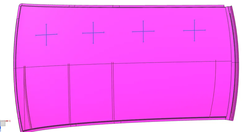
- Select the datum plane which is parallel to the outer roof surface and activate the sketch command. And create the 0-Y line in the center.
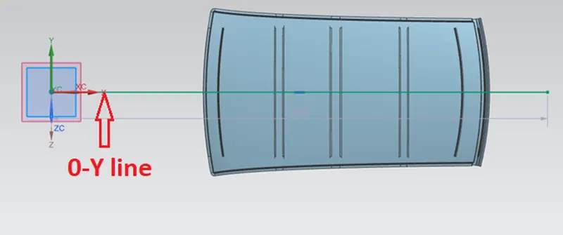
- Offset the curve from 0-Y line at 300mm distance.
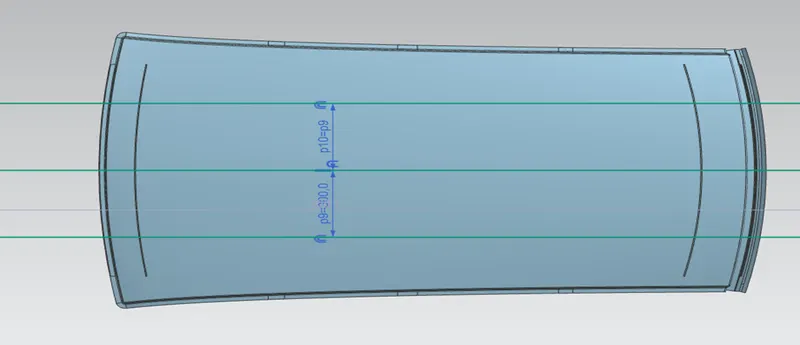
- Offset the 300 line at a distance of 100mm symmetrically.
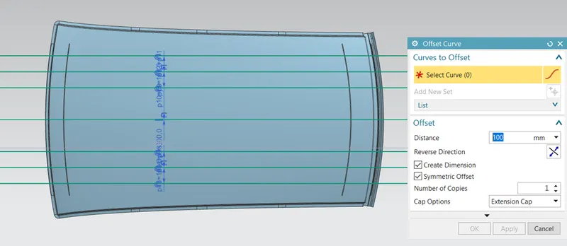
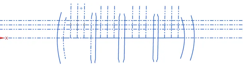
- Project all the curve of front roof rail, bow roof one, center roof, bow roof two and rear roof.
- Create the intersection point on the projection curve.
- Draw line between the points to create the midpoint.
- Draw the vertical mid line from the midpoint.
- Offset the vertical mid line to the distance of 100mm symmetrically on left and right direction.
- Create the intersection point on these line and close the sketch command.
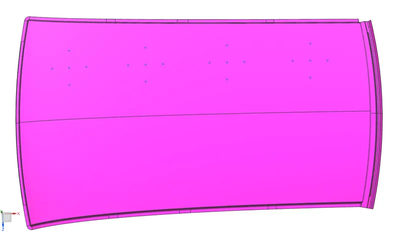
- Project the intersection point on the roof outer surface.
- To project the intersection point, click on the project curve command then select the point.
- After selecting point select the outer roof surface as object.
- Select the vector direction and the intersection point is projected on the outer roof surface.
- Draw the arc on these intersection point by choosing the 3 point arc command.
- Select the arc option then click on start point, end point and midpoint.
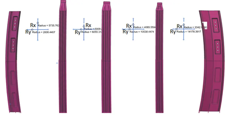
MEASURE THE Rx AND Ry VALUE
- Apply the local radius command on these arc for getting the Rx and Ry value.
- Local radius value on vertical arc is taken as Rx value and the local radius on horizontal arc is taken as Ry value.
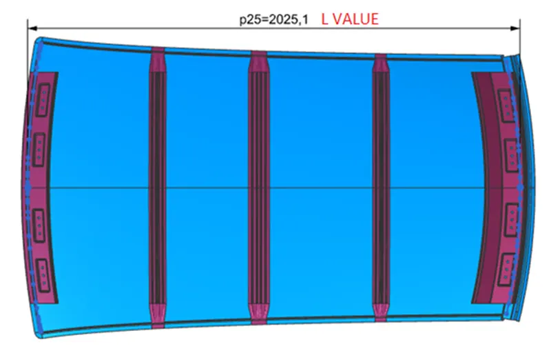
MEASURE 'L' VALUE
- Measure the ‘L’ value which is the length of the roof in X direction.
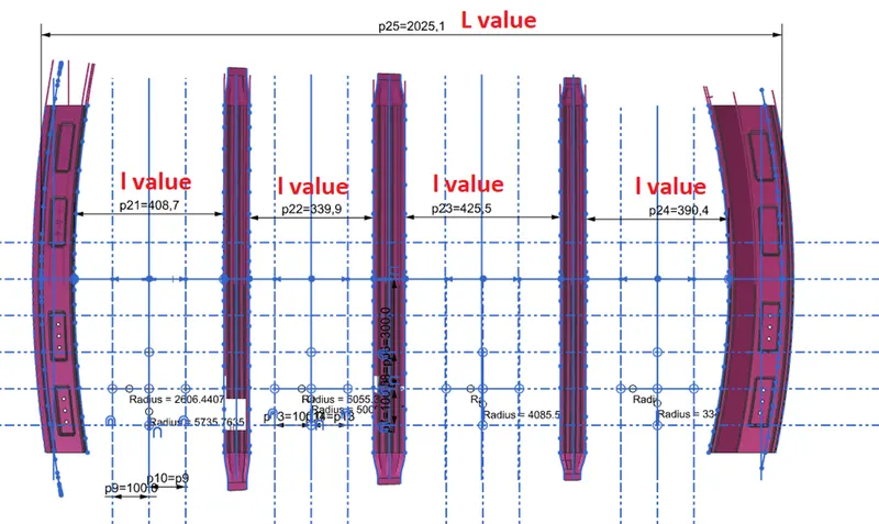
 MEASURE THE ‘l’ VALUE
- For case 1, ‘l’ value is taken from midpoint of front roof rail to bow roof one in X direction.
- For case 2, ‘l’ value is taken from midpoint of bow roof one to center roof in X direction.
- For case 3, ‘l’ value is taken from midpoint of center roof to bow roof two in X direction.
- For case 4, ‘l’ value is taken from midpoint of bow roof two to rear roof two in X direction.
Bow–Roof Prediction Formula
W = [1.73 x 10^(-3) x L] + [1.85 x 10^(-8) x (R^2)/t] + [ 1.10x10^(-3) x l] - 2.68
Where,
L = Roof Length in X-Direction[mm](Roof dimension in 0-Y)
R = Roof curvature
R = 2(Rx*Ry)/(Rx+Ry)
Rx = X curvature
Ry = Y curvature
t = Roof plate thickness [mm]
l = Bow Roof Span [mm]
Judgment Condition
OK< 2.7
| S.NO. | ROWs | Rx | Ry | R | I | L | t | R2/t | W | OK/NG |
| 1 | FR & 1st | 5735.76 | 2606.44 | 3584.17 | 408.68 | 2025.07 | 0.75 | 17128339.58 | 1.70 | OK |
| 2 | 1st & CR | 5009.26 | 6055.31 | 5482.84 | 339.87 | 2025.07 | 0.75 | 40082011.53 | 2.19 | OK |
| 3 | CR & 2nd | 4085.56 | 10038.45 | 5807.51 | 425.49 | 2025.07 | 0.75 | 44969602.17 | 2.40 | OK |
| 4 | 2nd & RR | 3342.99 | 14178.39 | 5410.33 | 390.39 | 2025.07 | 0.75 | 39028864.09 | 2.22 | OK |
RESULT
- If the heat distortion value is calculating less than 2.7mm then the heat distortion value shown good significant.
- If the heat distortion value is calculating more than 2.7mm then the heat distortion value shown not good significant and need some work like create extra bow roof, create emboss, increase or decrease the mid distance etc.
SNOW LOAD CRITERIA
Snow load is the downward force on a vehicle roof by the weight of snow and ice. The roof surface can be deform due to the snow load. Snow load criteria is done to analyze the roof surface, whether the roof withstand during winter in snow fall region. This study is also done to find whether the deformation is permanent after removing snow load. It may be bend due to load but needs to regain its original position.
If the plastic deformation occurs on roof then its not good significant and then it need to give strength to the roof.
HOW THE VALUE IS TAKEN FOR SNOW LOAD CRITERIA
- Select the datum plane which is parallel to the outer roof surface and activate the sketch command. And create the 0-Y line in the center.
- Offset the 0-Y line to the distance of 100mm symmetrically on upward and downward side.
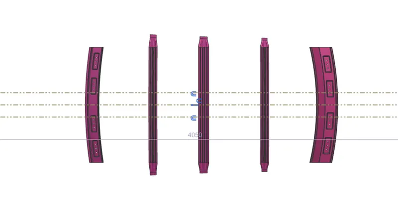
- Project the curve of front roof rail, bow roof one, center roof, bow roof two and rear roof.
- Create the intersection point in the projected curve.
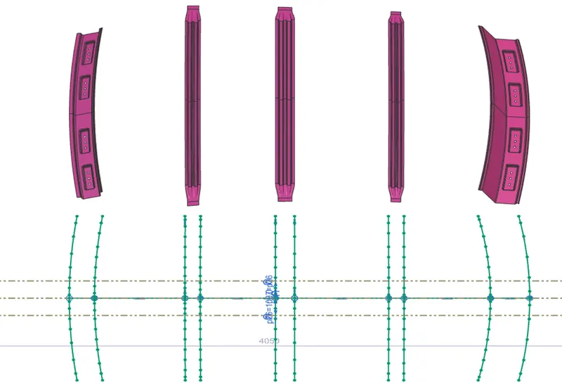
- Draw the line between these points.
- Draw the vertical mid line in between of these point.
- Create the intersection point in the vertical mid line.
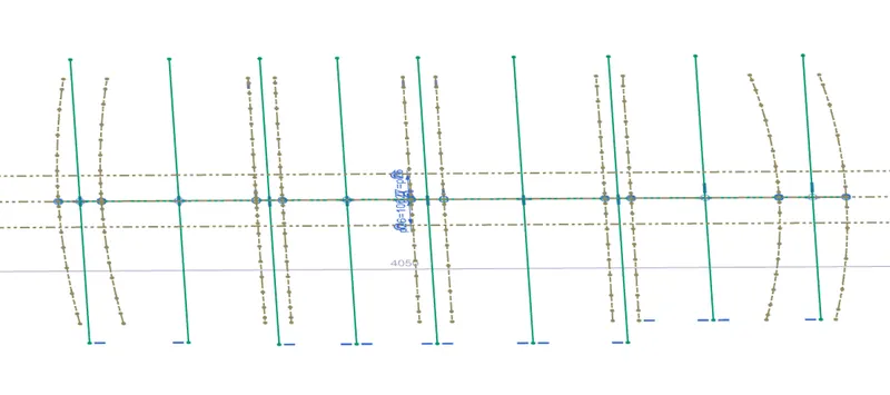
- Offset the mid line to the distance of 100mm symmetrically on left and right side.
- Crate the intersection point on the offset line.
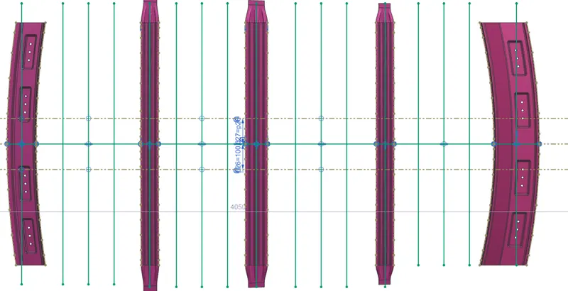
- Project the intersection point on the roof outer surface.
- To project the intersection point, click on the project curve command then select the point.
- After selecting point select the outer roof surface as object.
- Select the vector direction and the intersection point is projected on the outer roof surface.
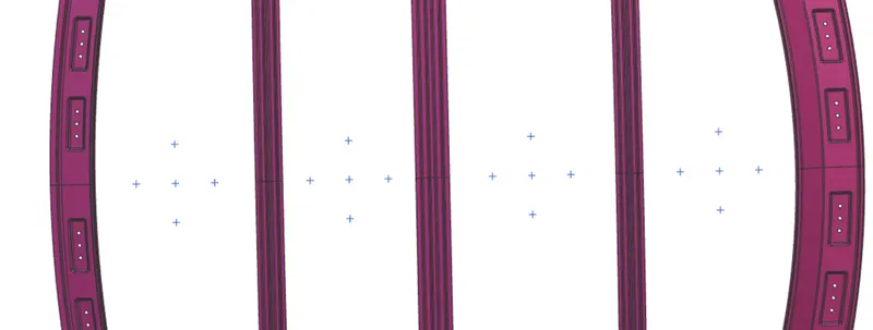
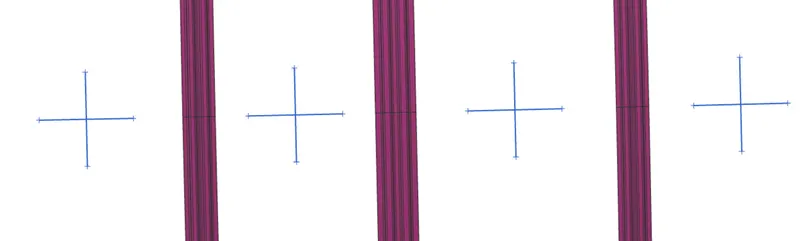
- Draw the arc on these intersection point by choosing the 3 point arc command.
- Select the arc option then click on start point, end point and midpoint.
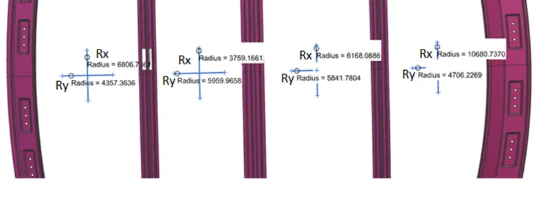
Rx AND Ry VALUE
- Apply the local radius command on these arc for getting the Rx and Ry value.
- Local radius value on vertical arc is taken as Rx value and the local radius on horizontal arc is taken as Ry value.
Lx value
- Project the roof outer curve on sketch command.
- Draw the vertical midline, which intersect this projected line.
- Create the intersection point on the projected line and vertical midline.
- Measure the vertical distance through intersection point.
- For case one
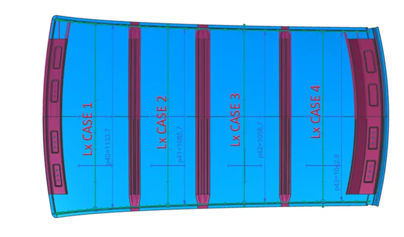
Y VALUE AND Ly VALUE
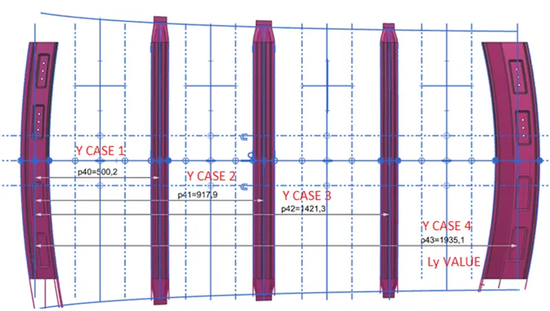
- Ly value is the distance calculating from center of front roof rail to the center of rear roof rail.
- Y value of each case is the distance calculating from center of front roof rail to the center of respective bow roof.
- For case 1- Distance from center of front roof rail to the center of bow roof one.
- For case 2- Distance from center of front roof rail to the center of center bow roof.
- For case 3- Distance from center of front roof rail to the center of bow roof two.
- For case 4- Distance from center of front roof rail to the center of rear roof.
L1 AND L2 VALUE
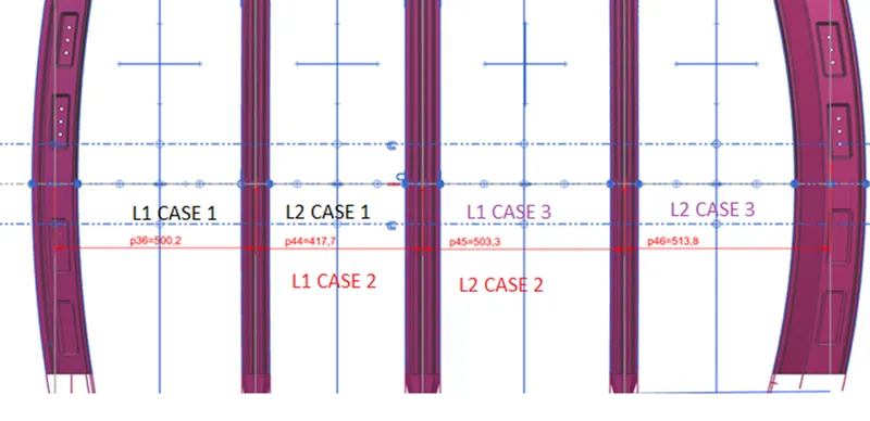
- FOR CASE 1
- L1 is distance from center of front roof rail to the center of bow roof one.
- L2 is distance from center of bow roof one to the center of center roof.
- FOR CASE 2
- L1 is distance from center of bow roof one to the center of center roof.
- L2 is distance from center of center roof to the center of bow roof two.
- FOR CASE 3
- L1 is distance from center of center roof to the bow roof two.
- L2 is distance from center of the bow roof two to the center of rear roof.
| S.NO. | ROWs | Ly | Lx | Y | ly | L1 | L2 | Rx | Ry | t | α | My | s | Qr | OK/NG |
| 1 | FR & 1st | 1935.06 | 1133.70 | 500.24 | 1980.25 | 500.24 | 417.69 | 6806.79 | 4357.3636 | 0.75 | 0.92 | 717759.33 | 458.97 | 8.44 | OK |
| 2 | 1st & CR | 1935.06 | 1085.73 | 917.93 | 2412.68 | 417.69 | 503.35 | 3759.17 | 5959.9658 | 0.75 | 1.10 | 933657.01 | 460.52 | 11.34 | OK |
| 3 | CR & 2nd | 1935.06 | 1058.65 | 1421.28 | 1996.37 | 503.35 | 513.78 | 6168.09 | 5841.7804 | 0.75 | 0.82 | 730228.48 | 508.56 | 7.48 | OK |
| 4 | 2nd & RR | 1935.06 | 1042.86 | 1935.06 | 513.78 | 10680.74 | 4706.2269 | 0.75 | 0.00 | 0.00 | 256.89 | #DIV/0! | OK |
RESULT
- If the value of snow load prediction calculation value is greater and equal to 3, then the snow load prediction shown good significant.
- If the value of snow load prediction calculation value is less than to 3, then the snow load prediction shown not good significant and need to give some strength to the roof.
CONCLUSION
To design the roof, also the consideration should be follow very well and after creating roof all the tested should be done like heat distortion value, snow load pridction, draft analysis, roof crust test etc. and if there have any variation of the car, then need to work on them. this is very important for our safety.