Roof Design
ROOF DESIGN CHALLENGE
ROOF is an automobile roof or car top is the portion of an automobile that sits above the passenger compartment, protecting the vehicle occupants from sun, wind, rain, and other external elements.Like many other automotive body panels, the roof is subjected to environmental conditions. Hail and snowstorms may burst, tree limbs and branches may fall, etc. All this can damage the roof and cause sharp dents, dings, and scratches.
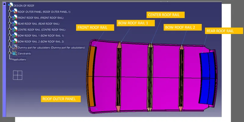
COMPONENTS IN ROOF DESIGN
1. Roof Outer Panel
REINFORCEMENTS,
2. Front Roof Rail
3. Bow Roof Rail 1
4. Center Roof Rail
5. Bow Roof Rail 2
If the roof is flat it is very weak and cannot able to with stand the forces like snow , so in order to increase the strength of the roof these reinforcements like front roof rail, central roof rail, rear roof rail and the bow roofs are introduced and joined to the flat surface of the roof with the different joining process
DESIGN CONSIDERATIONS
- Visibility criteria
- Head clearance
- Curvature study
- Heat Distortion and Snow load criteria
- Material thickness
ROOF OUTER PANEL:
First, we will be extracting the top half portion of the roof surface. Since the roof surface is symmetrical in shape, we can easily work only on half of the portion and reflect it at the end to create the whole roof. Also from the given input styling data, we are going to create the roof ditch areas on front , rear and sideways according to the given master section.
TOOLING AXIS CREATION
Using point option two points are created at the extreme ends of the roof outer panel. And by creating a point exactle at the centre between two extreme points. Using point-direction method in Y-AXIS a line is created called as TOOLING AXIS.
TOOLING AXIS is direction in which core moves to the cavity for creating required part
Orientations of ROOF OUTER PANEL
Isometric view
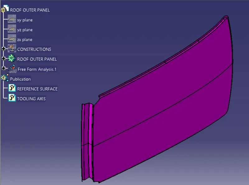
Front view
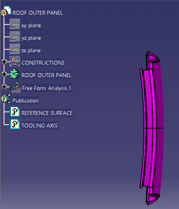
Top View
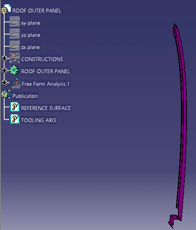
Right view
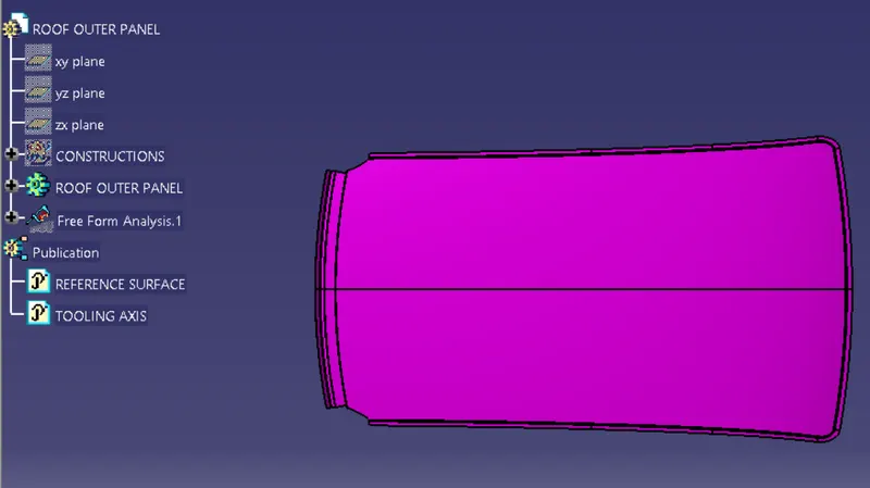
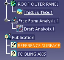
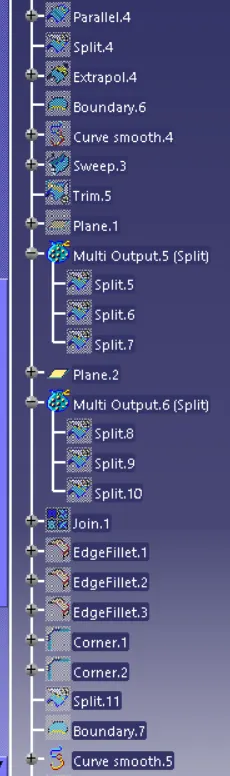
Model tree
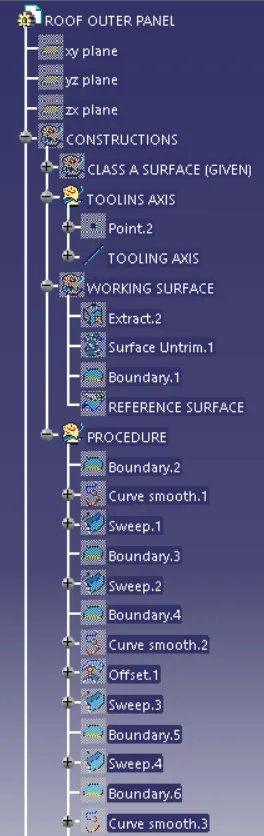
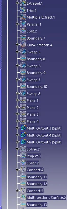
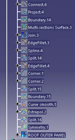
DRAFT ANALYSIS
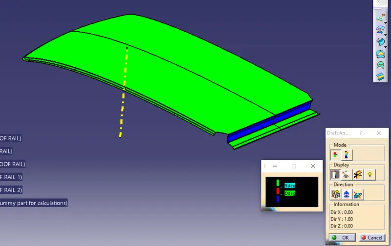
The area which is blue in color has 0° draft angle
FRONT ROOF RAIL
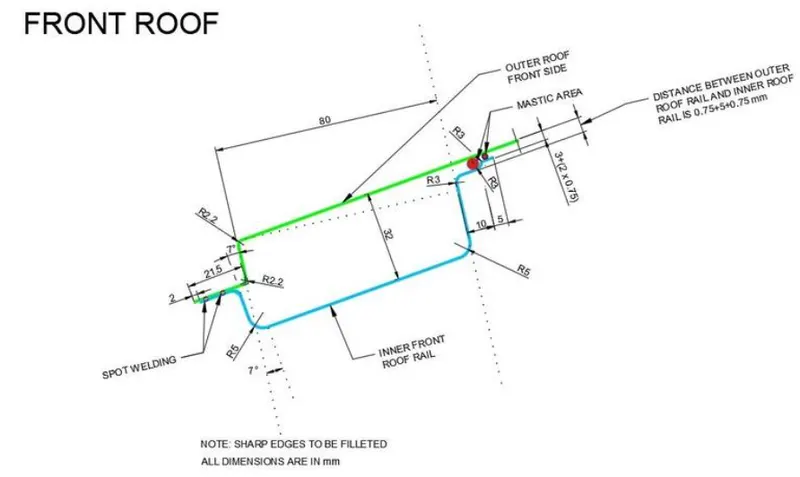
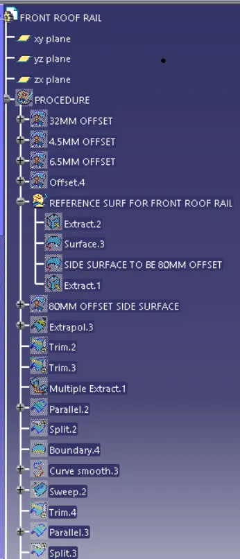
Front roof rail is the one which joins the wind shield glass , body side outer and the inner panel also. Here the front roof rail is designed based up on the master section given.
Orientations of FRONT ROOF RAIL
Isometric view
Front view
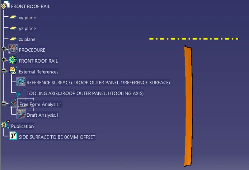
Top view
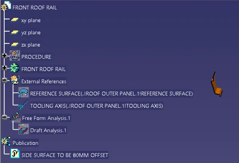
Right view
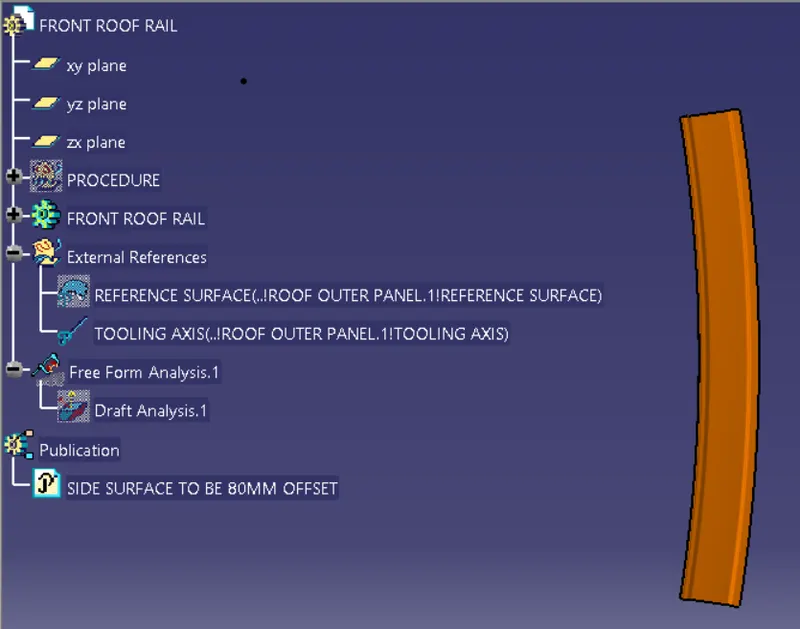
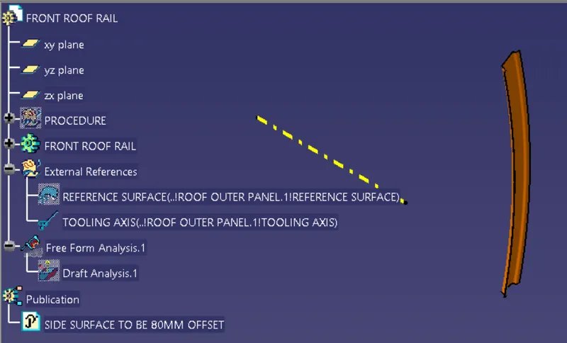
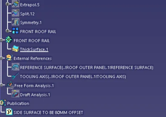
Model tree
DRAFT ANALYSIS
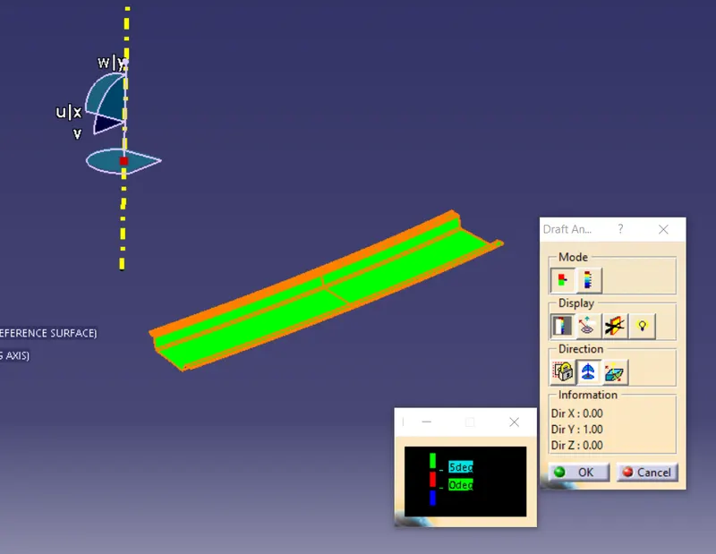
The area which is blue in color has 0° draft angle
BOW ROOF RAILS 1 & 2
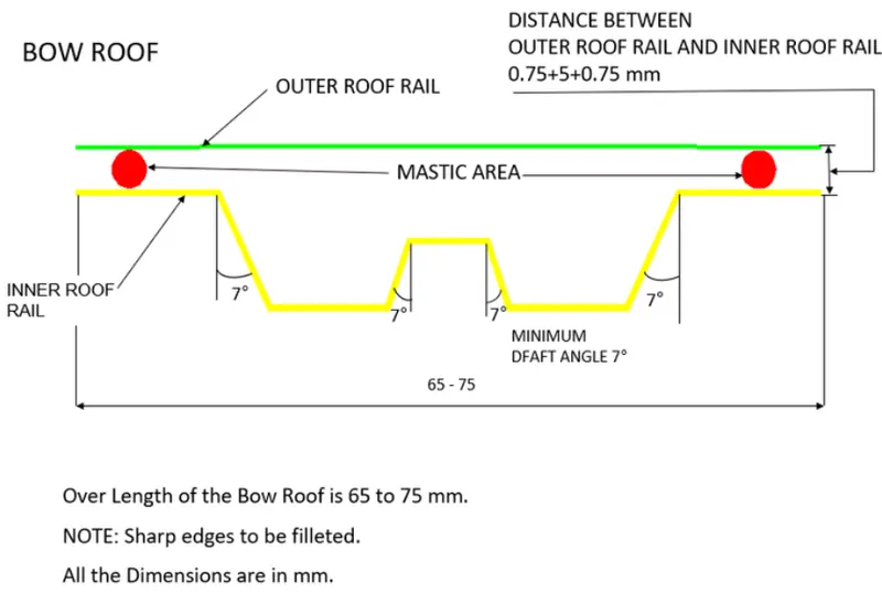
Bow roof center 1 is an additional stiffening member used in the roof assembly for the localised strength improvement and it is join directly to roof itself with several spot welding or even with mastic sealent.The bow roofs are give to improve the torsional stiffness and load bearing capacity of the roof structure . The number of bow roof present is depends on the overall size of the roof . Presently in this project two bow roofs are added.
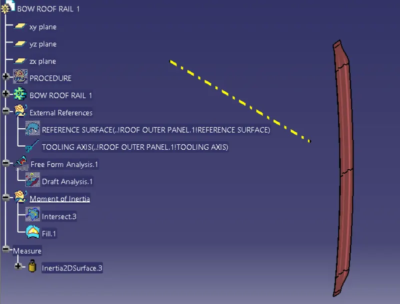
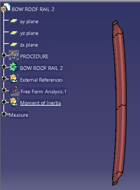
Orientations of BOW ROOF RAIL 1
Isometric view
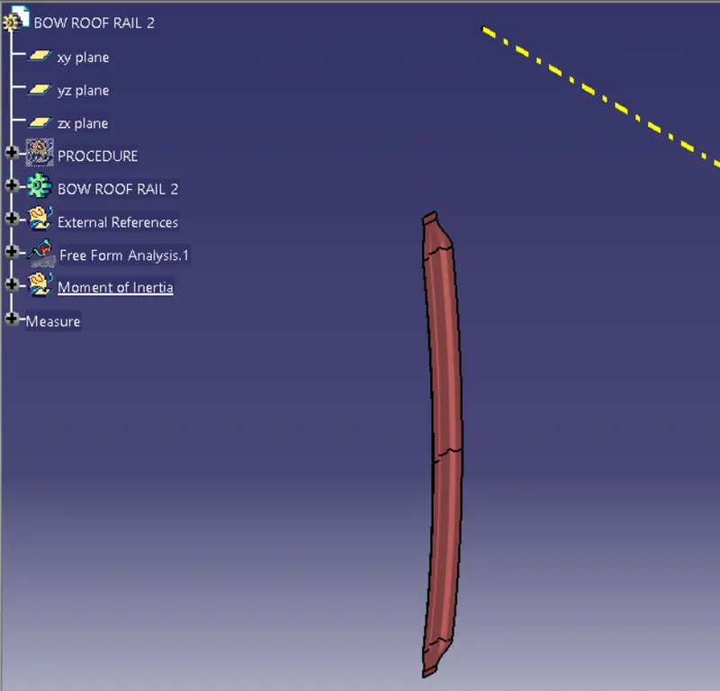
Front view
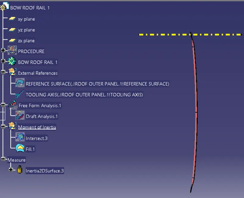
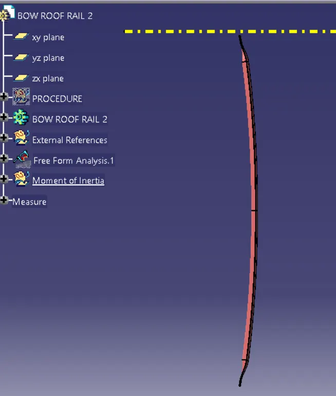
Top view
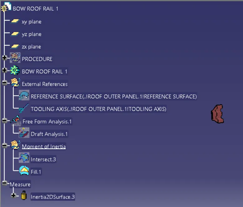
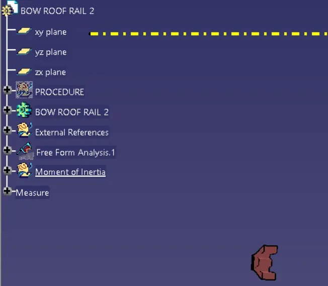
Right view
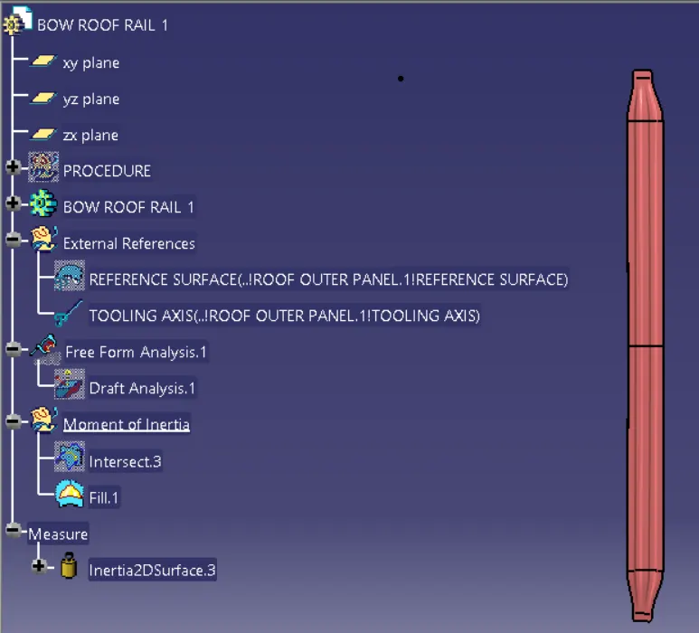
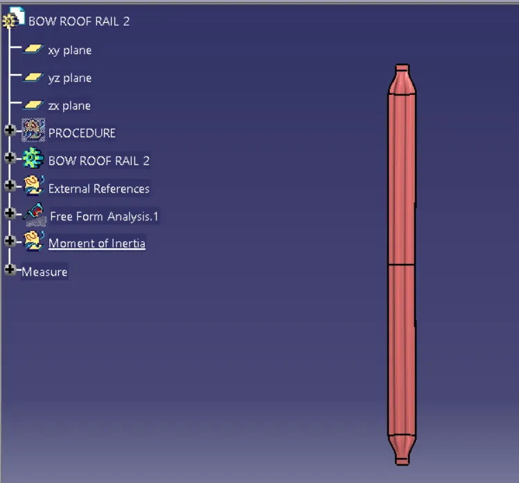
Model tree
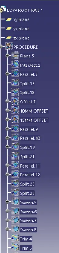
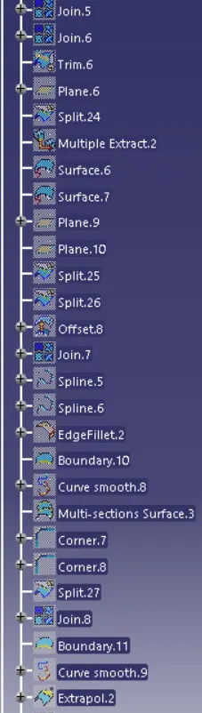
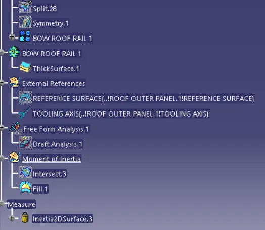
DRAFT ANALYSIS
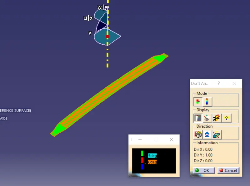
The area which is blue in color has 0° draft angle
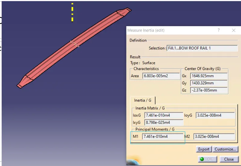
MEASUREMENT OF MOMENT OF INERTIA
Moment of Inertia is an important geometric property used in structural engineering, as it is directly related to the amount of material strength your section has. Generally speaking, the higher the moment of inertia, the more strength it has and the less it will deflect under load.
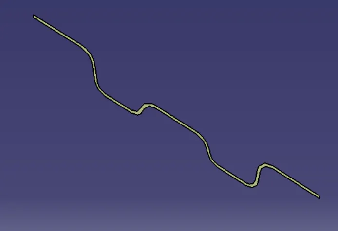
Procedure for creating moment of Inertia:
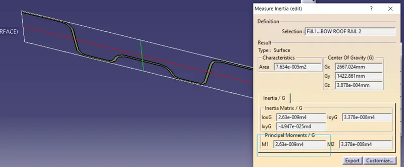
First step is to create intersection curve between XY plane and solid body of BOW ROOF RAIL 1. Then, it is filled using FILL option. Using moment of inertia option at the bottom, Moment of inertia is calculated.
CENTER ROOF RAIL
Central roof rail helps in providing effectively support to the flat area of the roof as it is more susceptible to failure under the action of load . Generally, central roof rail is placed at the center of the roof which is connected to the B-pillar support structure . This central roof rail helps in adding the strength to the roof during the rool- over test.
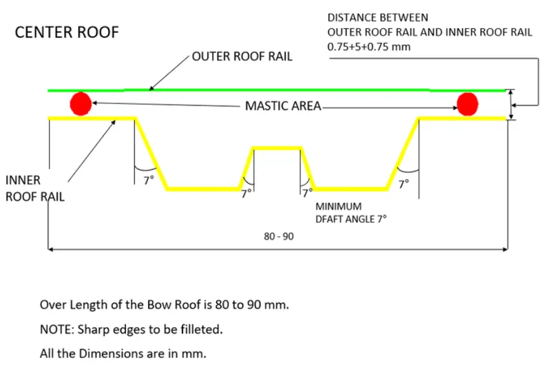
Orientations of CENTRE ROOF RAIL
Isometric view
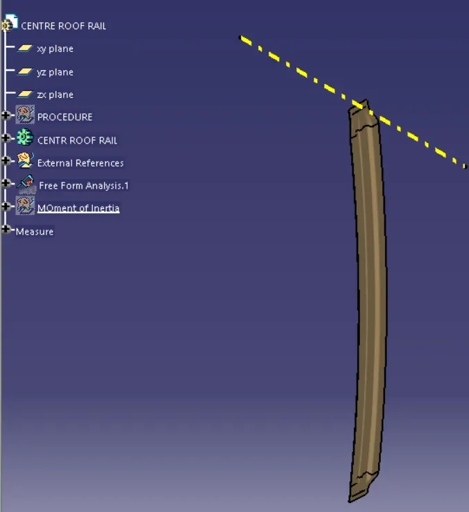
Front view
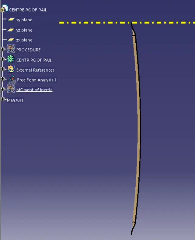
Top view
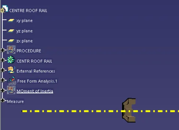
Right view
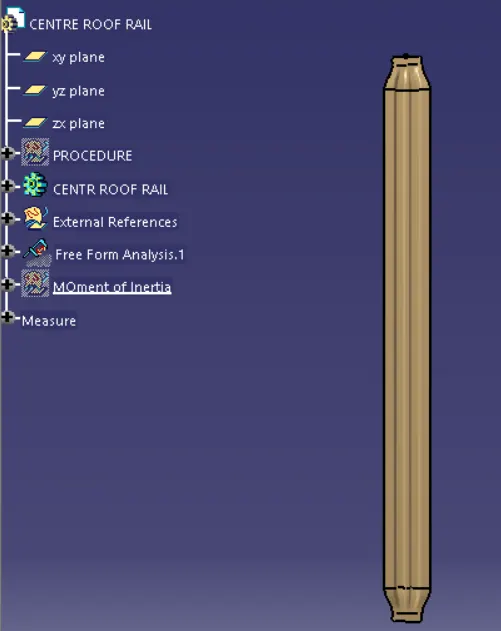
Model tree
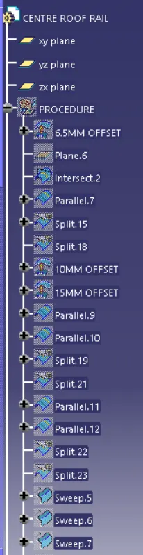
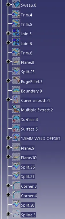
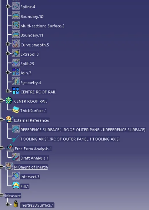
DRAFT ANALYSIS
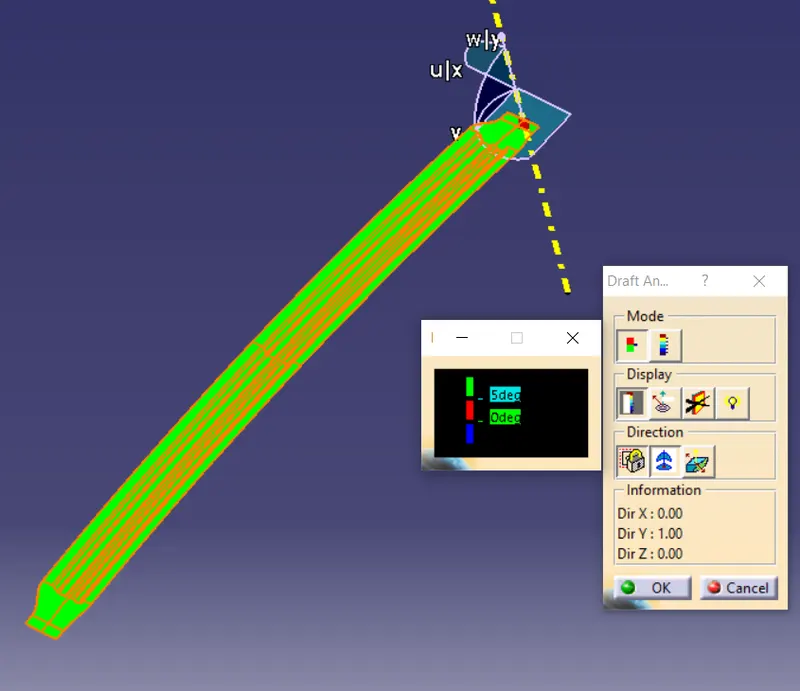
The area which is blue in color has 0° draft angle
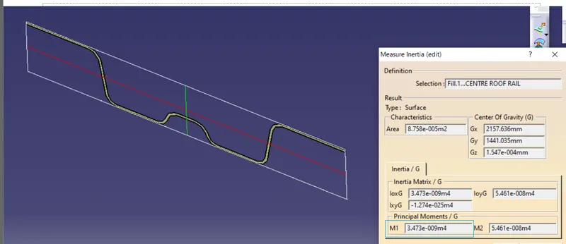
MEASUREMENT OF MOMENT OF INERTIA
Moment of Inertia is an important geometric property used in structural engineering, as it is directly related to the amount of material strength your section has. Generally speaking, the higher the moment of inertia, the more strength it has and the less it will deflect under load.
Procedure for creating moment of Inertia:
First step is to create intersection curve between XY plane and solid body of CENTRE ROOF RAIL . Then, it is filled using FILL option. Using moment of inertia option at the bottom, Moment of inertia is calculated.
JOINING PROCESS USED
Mastics are introduced between the roof outer panel and the reinforcements for joining . where ever the mastic are introduced there is remarkable improve of the strength
Spot welding is also introduced to join the reinforcements and the outer panel.
REAR ROOF RAIL
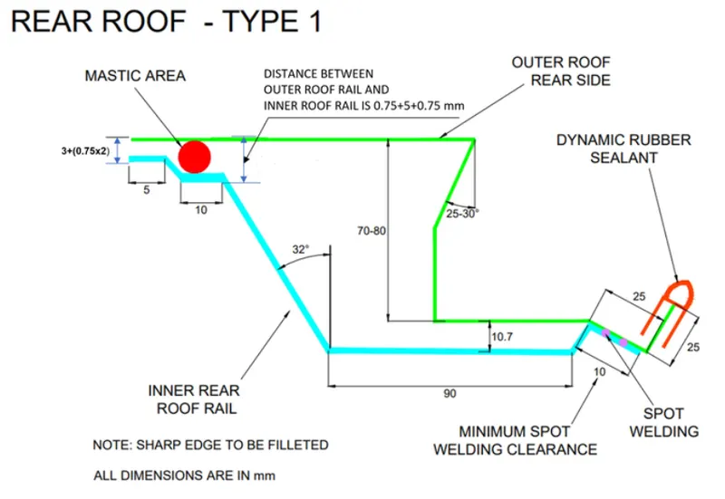
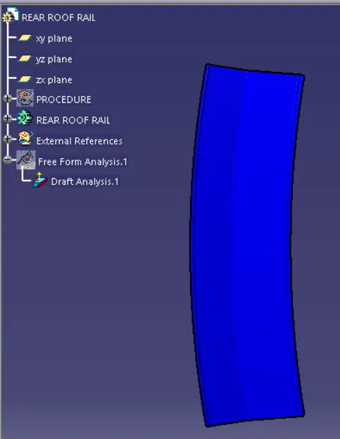
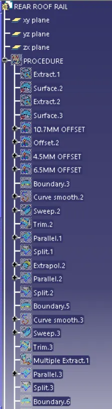
This roof rail joins with the back door and the roof. Inputs from the backdoor are taken into consideration for designing this roof rail.Here one end is joined using spot welding while the other end is joined using mastic sealants. We should take consideration of rear headroom and visibility criteria while desiging this
Orientations of REAR ROOF RAIL
Isometric view
Front view
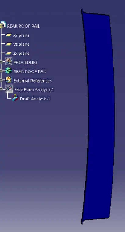
Top view
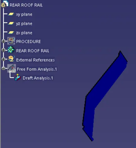
Right view
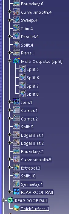
Model tree
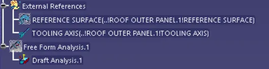
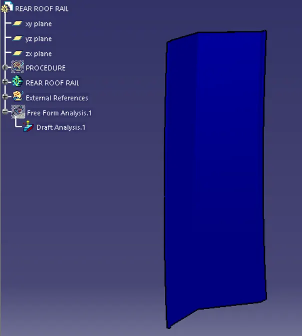
DRAFT ANALYSIS
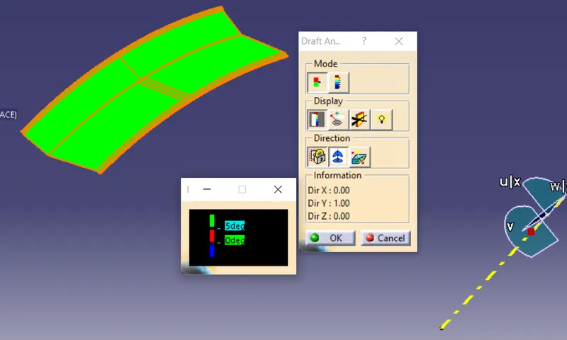
The area which is blue in color has 0° draft angle
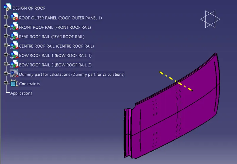
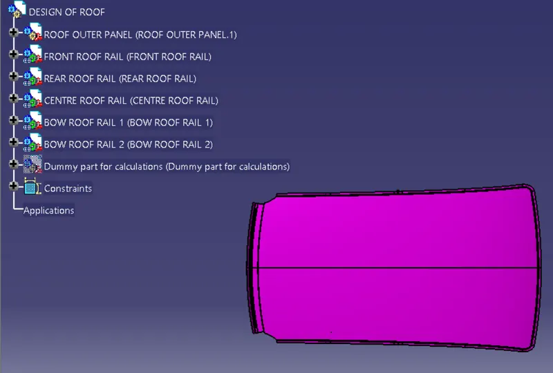
ROOF ASSEMBLY ORIENTATIONS
Isometric view
Front view
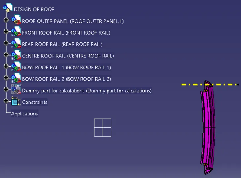
Top view
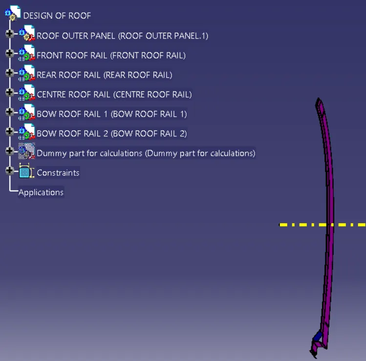
Right view
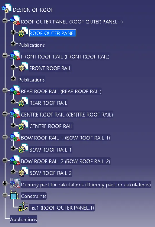
Non detailed model tree
CALCULATIONS IN ROOF DESIGN
Bow–Roof Prediction Formula
W = [1.73 x 10^(-3) x L] + [1.85 x 10^(-8) x (R^2)/t] + [ 1.10x10^(-3) x l] - 2.68
Where,
L = Roof Length in X-Direction[mm](Roof dimension in 0-Y)
R = Roof curvature
R = 2(Rx*Ry)/(Rx+Ry)
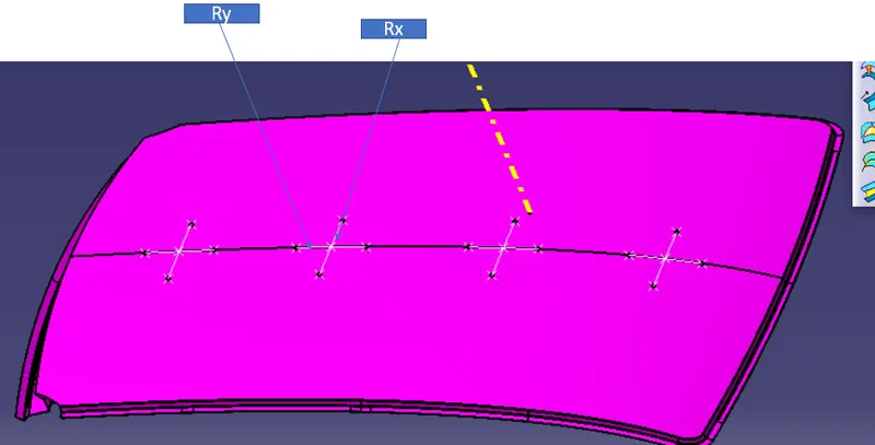
Rx = X curvature
Ry = Y curvature
t = Roof plate thickness [mm]
l = Bow Roof Span [mm]
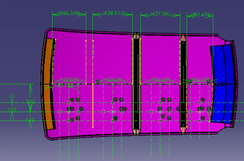
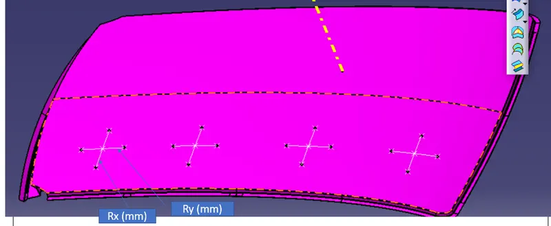
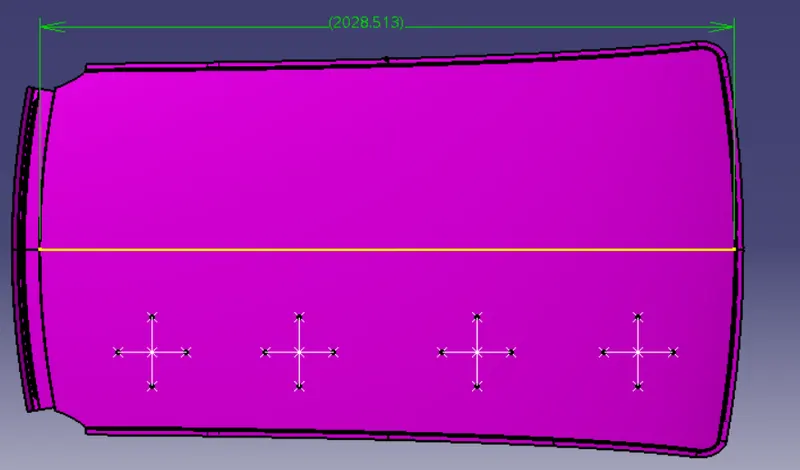
L= 2028.513mm
t= 0.75mm
FRR - BRR 1
Rx= 5739.286mm
Ry= 2503.107mm
R= 3,485.892mm
l= 366.336mm
W= 1.532 < 2.7
BRR1 - CRR
Rx= 4978.051mm
Ry= 6169.992mmm
R= 5,510.300mm
l= 428.512mm
W= 2.049 < 2.7
CRR - BRR2
Rx= 3976.309mm
Ry= 10581.972mm
R= 5,780.516mm
l=427.04mm
W= 2.123 < 2.7
BRR2 - RRR
Rx= 3321.824mm
Ry= 14308.892mm
R= 5,391.910mm
l=282.476mm
W= 1.857 < 2.7
Qr = [Iy x t^2] / [α x s x [(Rx + Ry)/2]^2 x 10^-8]
Where,
α = My x Lx^2 x 10^-12 , My = Y(Ly-Y)
t = Roof plate thickness [mm]
Ly = Distance between the front and rear roof Rails on the Vehicle along with 0Y[mm]
Length of Roof panel with the center point between Roof rail Front /Rear as the front and rear reference point.
Lx = Distance between the Left and Right end of the roof on the Roof BOW [mm]
The width of the roof panel is exposed on the surface.
Y = Distance front Front Roof Rail to Roof BOW[mm]
s = Distance for which Roof BOW bears divided load [mm]
s = L1/2 + L2/2
Iy = Geometrical moment of inertia of Roof BOW (Y cross-section )[mm^4]
Rx = Lateral direction curvature radius of roof panel Y cross-section on Roof BOW [mm]
Roof panel curvature Radius of the Length Lx in Front view
Ry = Longitudinal Direction curvature radius of the Roof panel X cross-section on Roof BOW [mm]
Roof panel X curvature radius of length s in Side view
Judgment condition
Qr ≥ 3.1
250 ≤ s ≤ 380
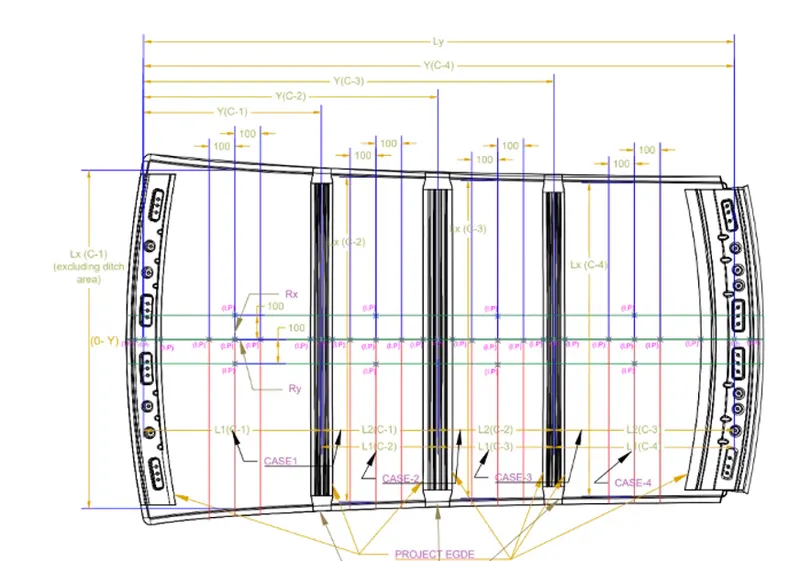
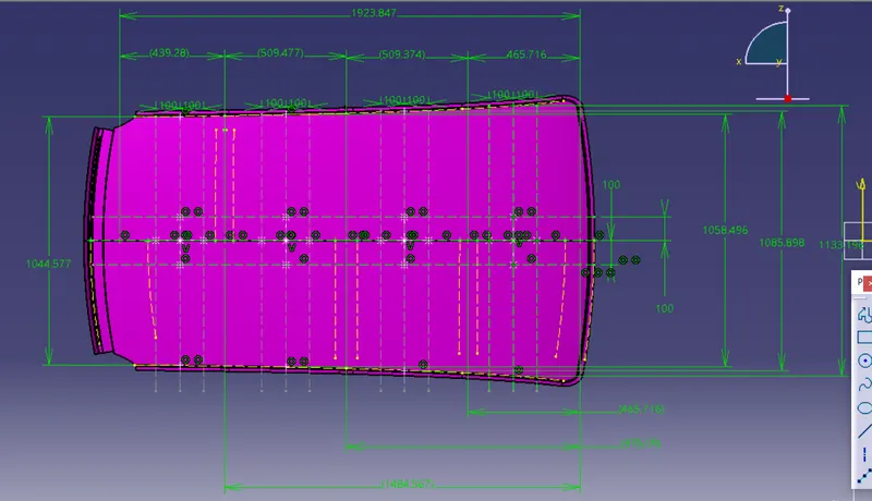
Ly= 1923.847 mm
t= 0.75 mm
BRR 1
Iy= 2630 mm^4
CRR
Iy= 3473 mm^4
BRR2
Iy= 2630 mm^4
FRR - BRR1
Lx= 1133.196 mm
Rx= 4409.122 mm
Ry= 2782.533 mm
Y= 465.716 mm
L1= 465.716 mm
L2= 509.374 mm
Qr = [Iy x t^2] / [α x s x [(Rx + Ry)/2]^2 x 10-8]
α = My x Lx^2 x 10^-12 , My = Y(Ly-Y)
My= 679074.9368, α= 0.8792
s = L1/2 + L2/2= 487.545
Qr= 26.69≥ 3.1
BRR1- CRR
Lx= 1085.848 mm
Rx= 3769.239 mm
Ry= 6219.874 mm
Y= 975.09 mm
L1= 509.374 mm
L2= 509.477 mm
Qr = [Iy x t^2] / [α x s x [(Rx + Ry)/2]^2 x 10-8]
α = My x Lx^2 x 10^-12 , My = Y(Ly-Y)
My= 925123.463, α= 1.0907
s = L1/2 + L2/2= 509.425
Qr= 14.094≥ 3.1
CRR-BRR2
Lx= 1058.496 mm
Rx= 4270.693 mm
Ry= 11024.271 mm
Y= 1484.567 mm
L1= 509.477 mm
L2= 439.28 mm
Qr = [Iy x t^2] / [α x s x [(Rx + Ry)/2]^2 x 10-8]
α = My x Lx^2 x 10^-12 , My = Y(Ly-Y)
My= 652140.591 , α= 0.7306
s = L1/2 + L2/2= 474.378
Qr= 7.298≥ 3.1
Conclusion: Thus, the strength of the reinforcements can be improved by proving embosses and soem cuts along its perimeter surfaces.