Roof Design
Design Of Roof
Aim : To Design a Roof with its components by following the master section of the front roof rail with all the design parameter, Perform Draft Analysis and do the curvature study on the roof based on the Bow roof prediction calculation as well as the manufacturing techniques.
SOFTWARE USED: NX 12.0
- To design the Sheetmetal ROOF in NX by using some Solid/Surface features.
- NX Software is a flexible and powerful integrated solution that helps you deliver the products faster and efficiently.
- NX Cad software is widely used automotive, aerospace, thermal power station. Because of it is having modelling, drafting and manufacturing platform.
Roof :
An automobile roof or car top is the portion of an automobile that sits above the passenger compartment, protecting the vehicle occupants from sun, wind, rain, and other external elements.
When it is seeing from outside of the car, it is just closing the top portion. But in design point of view, it is hard to create the design. Because of you have to create no of support rails for enough strength to withstand the load. Bow roofs are primarily fixed in flatter region to enhance strength.
Front roof and rear roof rails are fixed to the ditch area using spot weld operation. But front, rear bow roof and center roof rails are fixed to roof using mastic sealants. We don’t want so much gap between roof rails and bow roof area. So, we reducing the NVH issues.
DESIGN CONSIDERATION OF ROOF:
- Visibility criteria
- Head room clearance
- Bow roof position
- Heat distortion and Snow load criteria
- Draft analysis
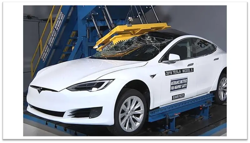
ROOF CRUSH TEST:
Roof strength evaluations consist of a quasi-static test conducted on a vehicle’s roof in a manner similar to tests used to judge compliance with Federal Motor Vehicle Safety Standard 216 (Office of the Federal Register, 2009). The main differences between the procedure specified by the Insurance Institute for Highway Safety (IIHS) and that specified by the U.S. federal government are that the IIHS procedure are,
- Specifies testing one side of a vehicle’s roof
- Does not include a headroom criterion
- Specifies testing to a given displacement instead of a given force level
- Specifies setting the vehicle’s pitch angle during testing based on the measured on-road pitch angle.
An overall rating is assigned based on the peak strength-to-weight ratio (SWR) measured within 127 mm of plate displacement.
Roof Design :
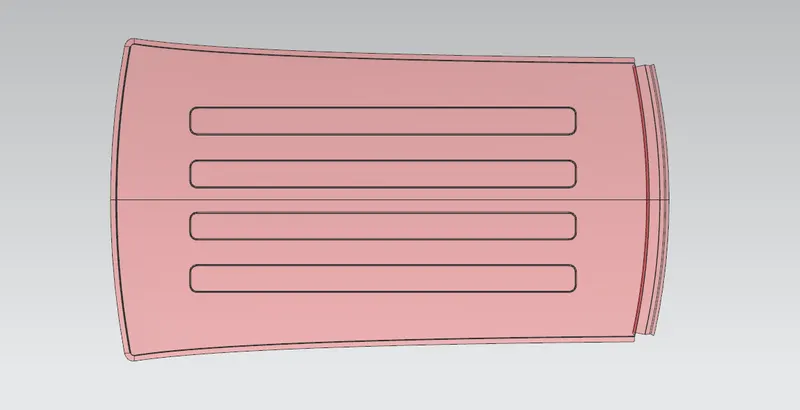
Developed essential flanges and ditch area for the given roof styling surface
with Thicknes = 0.75
and Draft Angle : 3-5 degrees
- for deep drawing we give 3 degree angle.
- and for flange length we give 21.5 mm for supporting the windshield glass, mastic and glass sealent.
- If we give angle less than 3 degree we face problen in deep drawing and if we angle greater than 3 degree we face problem in passenger viewing angle.
Design of Roof Rails:
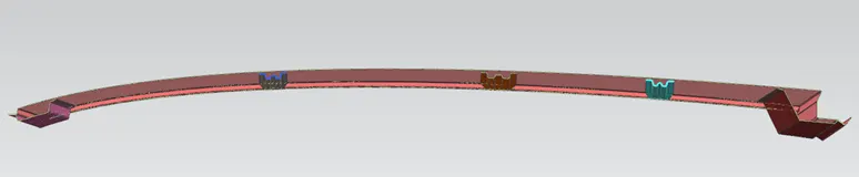
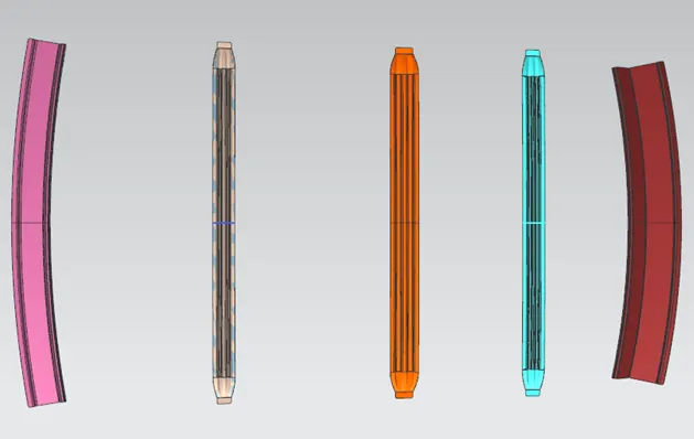
Roof rails are designed according to master sections provided.
in sequence
1. Front Roof Rail
2. Bow Roof Rail 1
3. Center Roof Rail
4. Bow Roof Rail 2
5. Rear Roof Rail
Thickness of each roof rail = 0.75 mm
DRAFT ANALYSIS
Draft analysis is performed on the components where the ejection of materials happens after the material is made inside the tools. In the case of Automotive Sheet Metal manufacturing, the blank sheet after turning into automotive panels like Hood, Fender, Roof, Side Doors, Back Doors are seen.
The Draft Analysis command in NX enables you to detect if the part you drafted will be easily removed. This type of analysis is performed based on color ranges identifying zones on the analyzed element where the deviation from the draft direction at any point, corresponds to specified values.
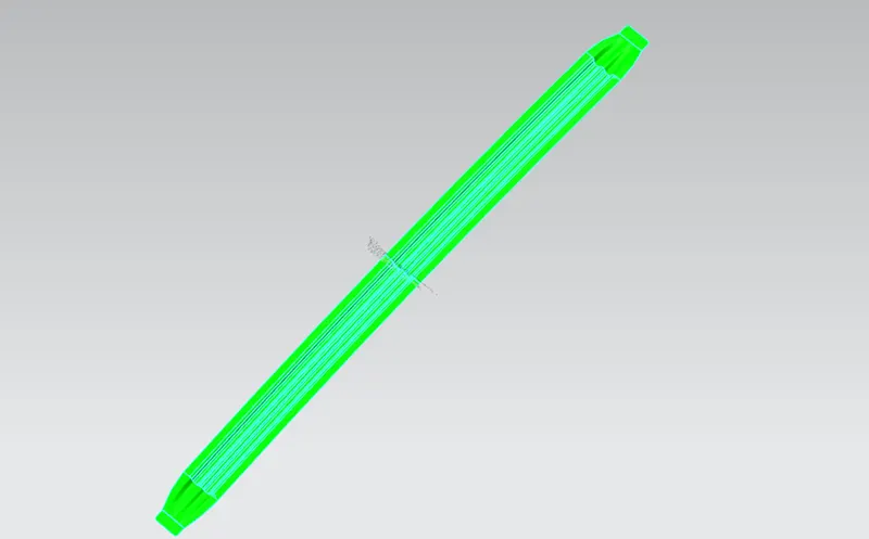
Minimum draft angle is 7 degree is considered for analysis. Green colour show positive draft angle of the part equal or more than 7 degree.
Draft Analysis Of Roof
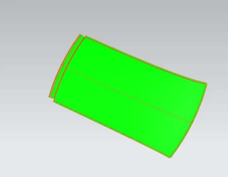
Following are the Roof Rails And their Draft Analysis
Front roof rail :
Front roof rail is used to provide strength to the roof panel front and it also acts as link between windshield glass, roof panel and headliner(interior trim). Headroom clearance and visibility are two important criteria for the driver and both of them depends upon the front roof rail dimensions, hence it is important to select appropriate dimensions for the roof rail.
Front Roof Rail Draft Analysis
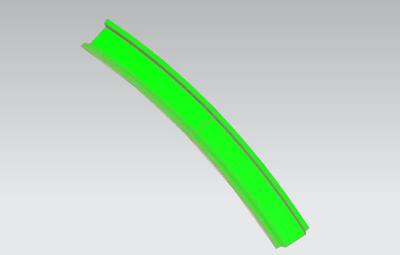
Bow Roof Rail :
The roof bows are usually metal and extend in a cross-car manner between metal side rails which are oriented in a generally fore and aft manner. They can be more then 1.
Draft Analysis Of Bow Roof Rail 1
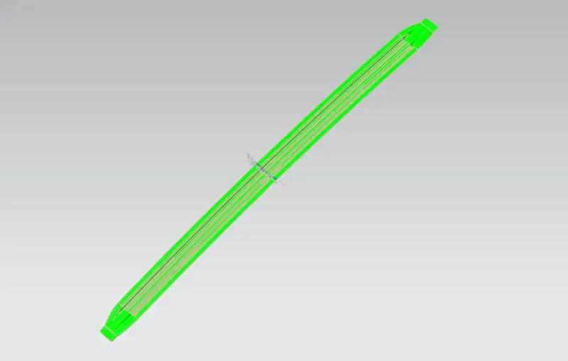
Draft Analysis Of Bow Roof Rail 2
Center Roof Rail :
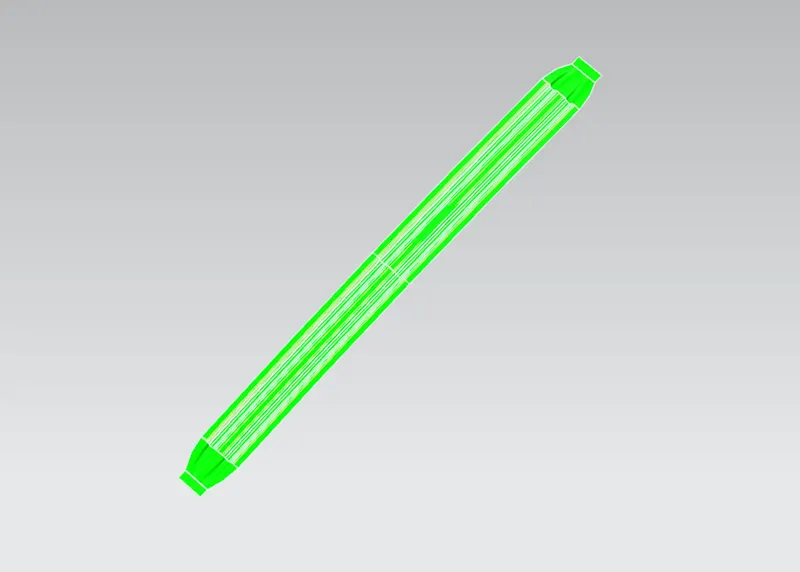
Center Roof Rail is the center most roof support rail in a car, its greater in dimensions then the bow roof. Reinforcement is also provided to the Center Roof Rail when 'Sunroof ' is installed in a car, as the sunroof takes the posion of the bow roof, reinfocement is given to center roof rail.
Draft Analysis Of Center Roof Rail
Center Roof Rail with Reinforcement
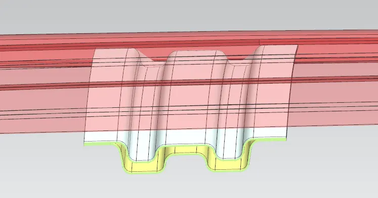
Rear Roof Rail :
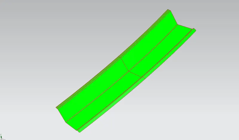
It is the rearmost rail of the car, it provides support to the roof as well as the back door is installed on it.
Draft Analysis Of Rear Roof Rail
Roof Specifications and Its Curvature Study :
The delivery tests specified for roof assembly are static, dynamic and impact. The purpose of static testing is to verify that roof assembly exhibits no permanent deflection due to distributed load representing snow load and due to heat distortion.
Before sending the CAD models to the simulation team it is important to justify the position of the bow roof and their bow span. It actually leads to the prevention of most of the problems that may occur in the design stage. There are two ways in which we can perform this study Before performing the study we ourselves analyse the roof curvature.
CURVATURE STUDY ON THE ROOF:
- Heat Distortion
- Snow Load
HEAT DISTORTION:
The heat distortion study the plays an important role in Sheetmetal application. Heat distortion is temperature limit above which material cannot be used for structural application. This study is useful to fin the where the material starts to soften when exposed to a fixed load at elevated temperature. In order to avoid the bending, damage to the roof based on the heat distortion temperature. This study will provide the which position of the bow roof give enough strengthen to roof.
Bow Roof Prediction Formula : HEAT DISTORTION CRITERIA:
W = [1.73 x 10^(-3) x L] + [1.85 x 10^(-8) x (R^2)/2] + [1.10 x 10^(-3) x I]-2.68
Judgement Condition: OK < 2.7
Where,
L= Roof Length in X- direction [mm](Roof Dimension in 0-Y)
R = Roof curvature
R = 2(RX*RY)/(RX+RY)
RX = X Curvature
RY = Y Curvature
t = Roof plate thickness [mm]
I = Bow roof span [mm]
Thickness for the Roof(t):
Roof Outer Panel, t= 0.75mm
Front Roof Rail, t = 0.75mm
Rear Roof Rail, t = 0.75mm
Bow Roof Rail Front, t = 0.75mm
Bow Roof Rail Rear, t = 0.75mm
Reinforcement roof rail, t = 0.75mm
Length Of Roof ( L ) = 2029.2422
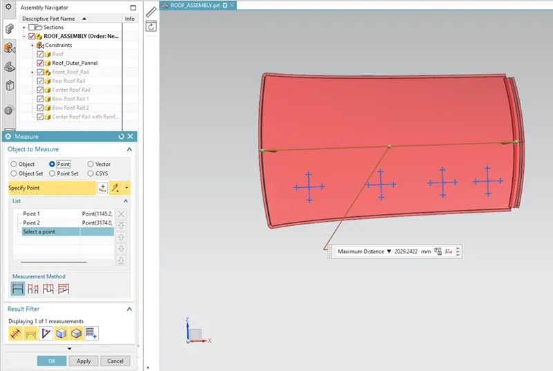
Length will remain same through out the calculations
For Cas1
( Front roof rail – Bow roof Rail 1 )
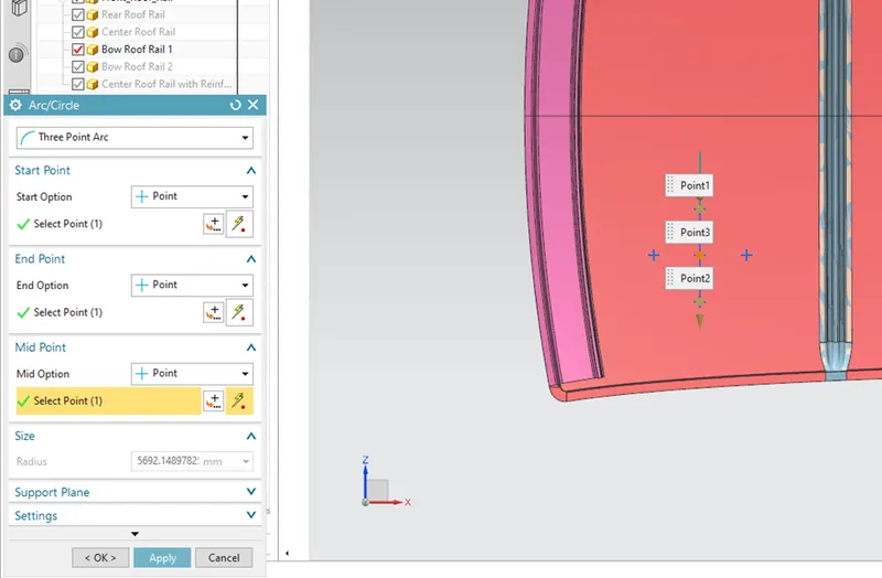
Rx = 5692.14897
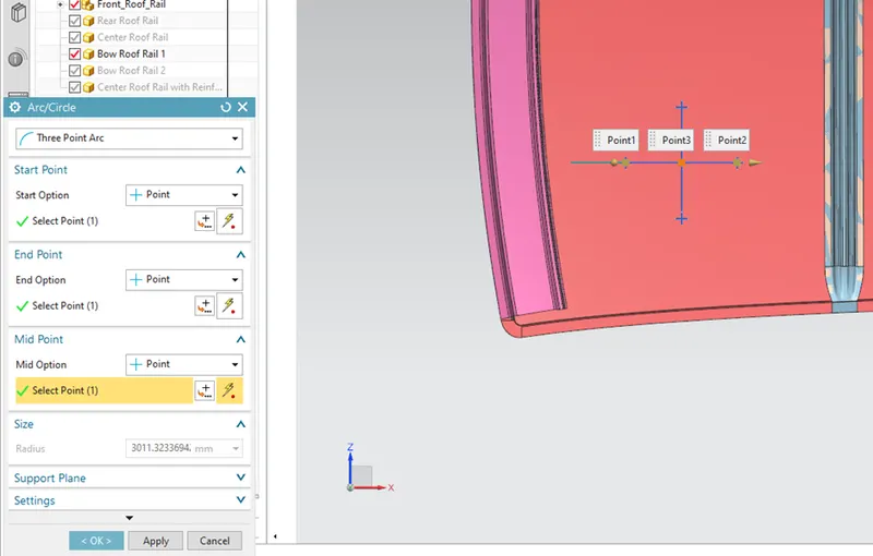
Ry = 3011.32336
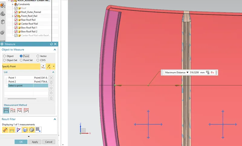
I1 = 516.5299
For Case 2
( Bow roof rail 1 – Centre roof Rail )
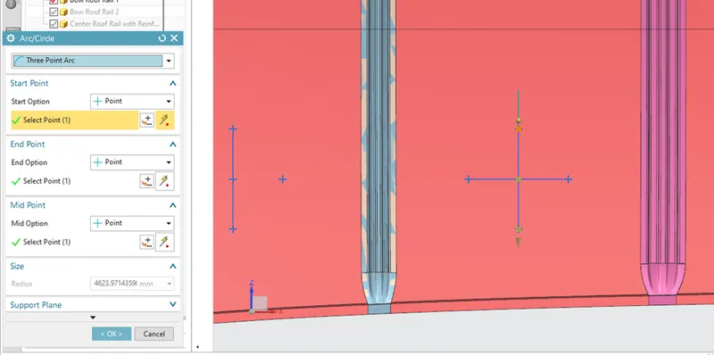
Rx = 4623.97143
Ry = 7601.8867
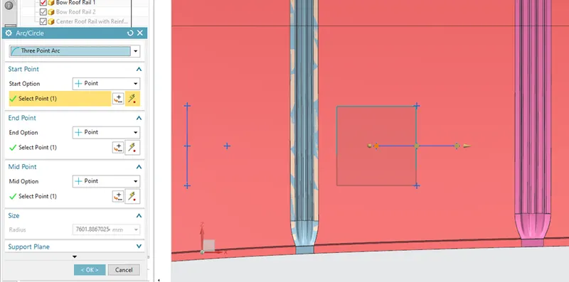
I2 = 490.6522
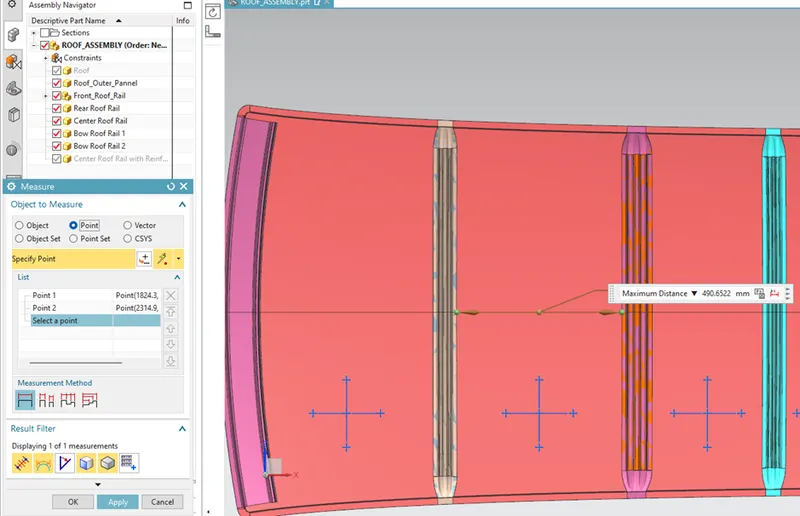
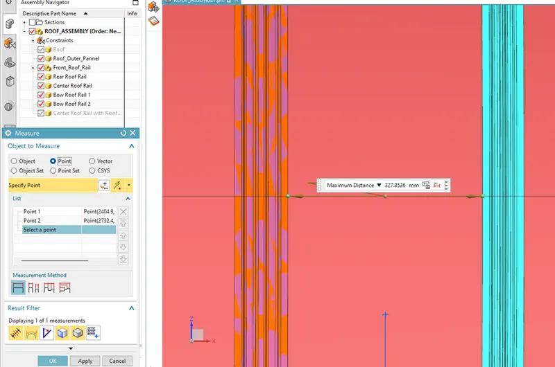
For Case 3
( Centre Roof Rail – Bow Roof rail 2 )
Rx = 3726.1657
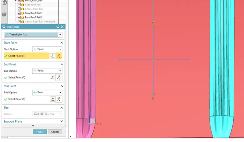
Ry = 11900.247835
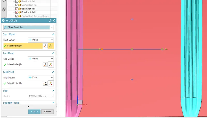
I3 = 327.8536
For Case 4
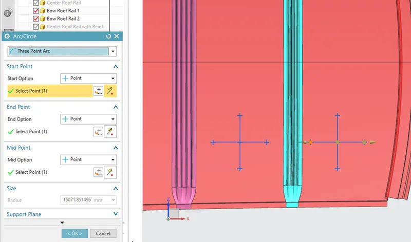
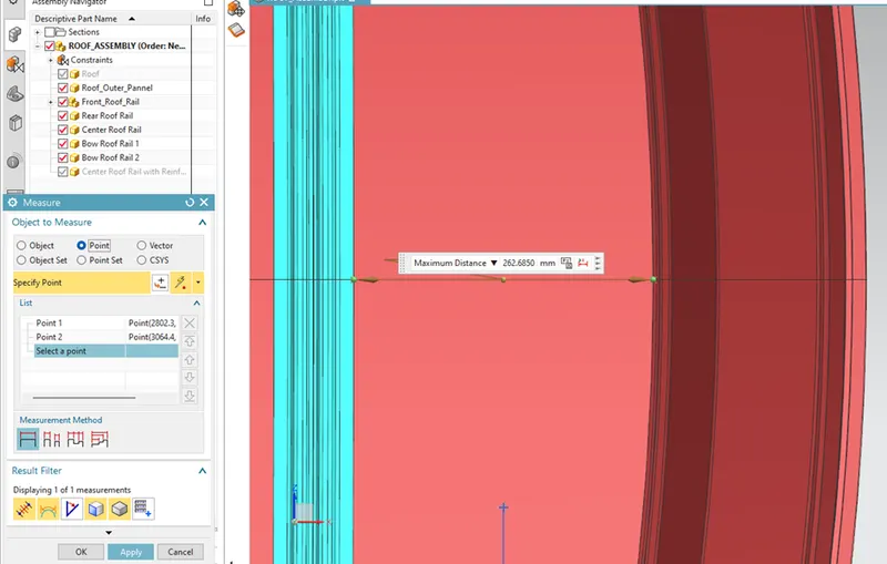
( Bow Roof Rail 2 – Rear Roof Rail )
Rx = 3206.5362
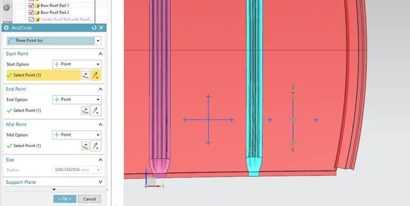
Ry = 15071.85149
I4 = 262.6850
FINAL RESULTS OF HEAT DISTORTION:
We have the necessary values for finding the heat distortion value(W):
W = [1.73 x 10^(-3) x L] + [1.85 x 10^(-8) x (R^2)/2] + [1.10 x 10^(-3) x I]-2.68
Apply the all the values,
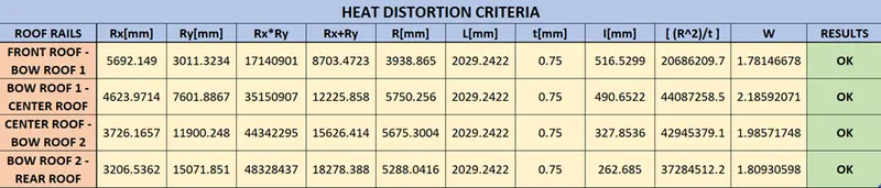
From the above table we, conclude that all the values are of W< 2.7 . So, that all bow roofs areas are placed at the right place.
SNOW LOAD:
Snow load criteria study is used to check the durability of the roof to withstand the snow fall on the roof and reflex it is original shape without any permanent deformation after load being removed.
SNOW LOAD CRITERIA:
Qr = [IY x t2] / [α x s x [(RX + RY)/2]2 x 10-8]
Where,
α = My x LX2 x10-12, My = Y(Ly–Y)
Judgement condition = Qr > 3.1
250 < s < 380
t = Roof plate thickness[mm]
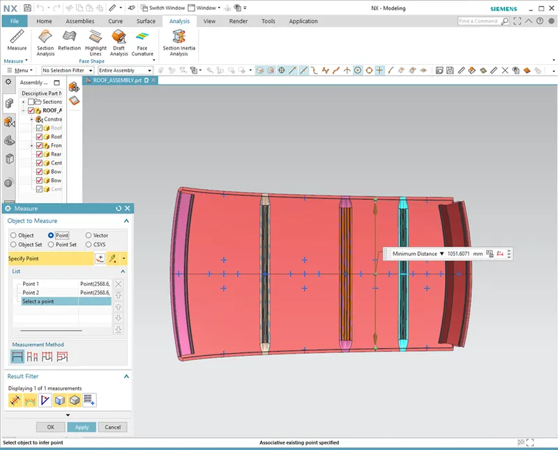
LY = Distance between the front and rear roof rails on the vehicle along with 0Y[MM],
Length of roof panel with the center point between roof rails front/ rear as the front and rear reference point.
LX= Distance between the left and right end of the roof on the roof bow[mm],
With of the roof panel exposed on the surface.
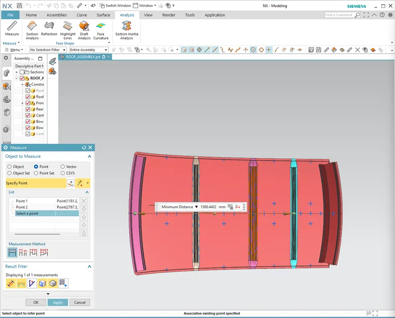
Y = Distance between Front roof rails to roof bow [mm],
s = Distance for which roof bow bears divided load [mm],
s = L1/2 + L2/2
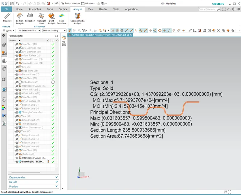
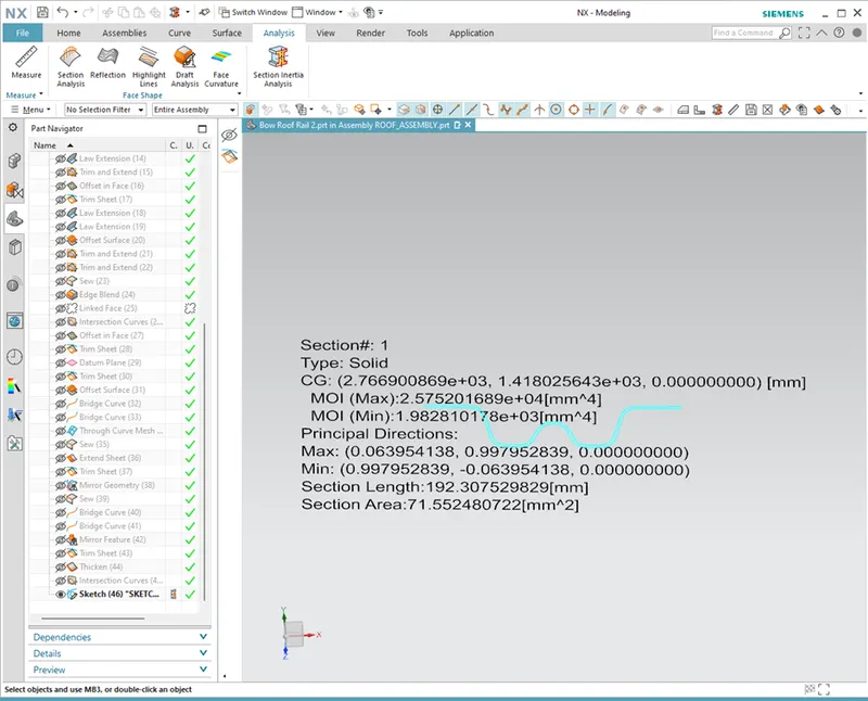
Iy = Geometrical moment of inertia of roof bow (Y cross – section) [mm4],
RX = Lateral direction curvature radius of roof panel Y cross section on roof bow [mm4],
Roof panel curvature radius of the length LX in front view.
RY = Longitudinal direction curvature radius of the roof panel X cross section on roof bow[mm4],
Roof panel X curvature radius of length s in side view.
RX & RY (X & Y Curvature):
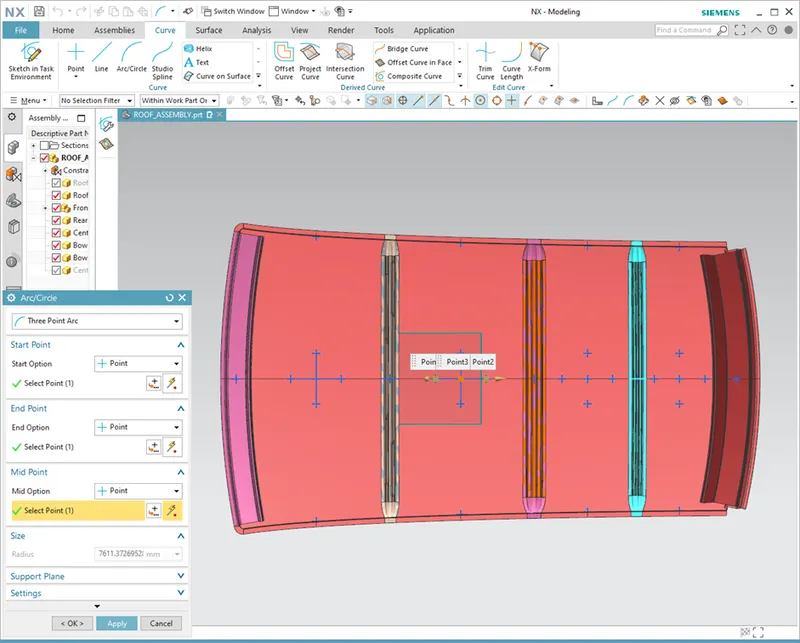
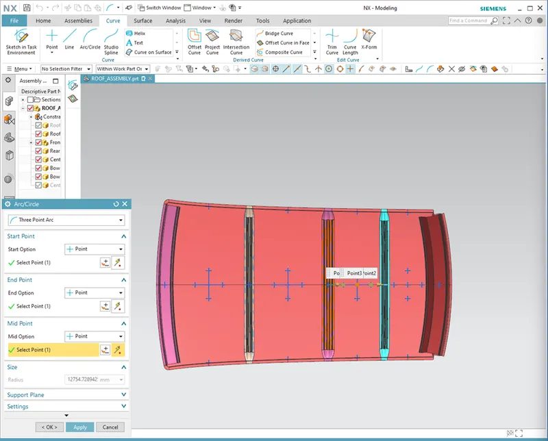
- At 0-Y axis on perpendicular plane to roof. Draw 100mm lines offset to either side of the of 0Y axis line. Now center lines are drawn between each adjacent roof rail respective. Intersection points are marked on the sketch. Make all the geometry in construction lines except points.
- Project the intersection points in the sketch are projected to roof surface.
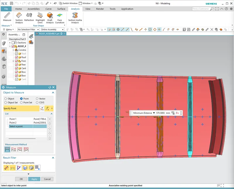
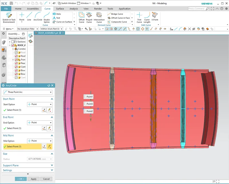
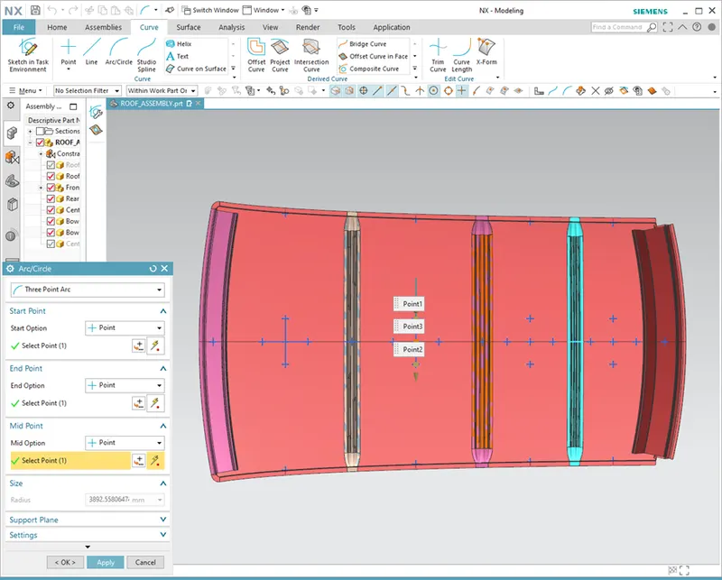
- Join the project points using arc curve and measure the radius value using minimum radius comment.
Ly = 1976.3089
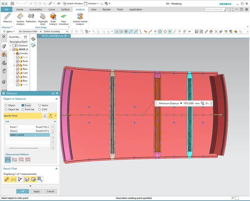
Length will be same through out the calculations
For Case 1
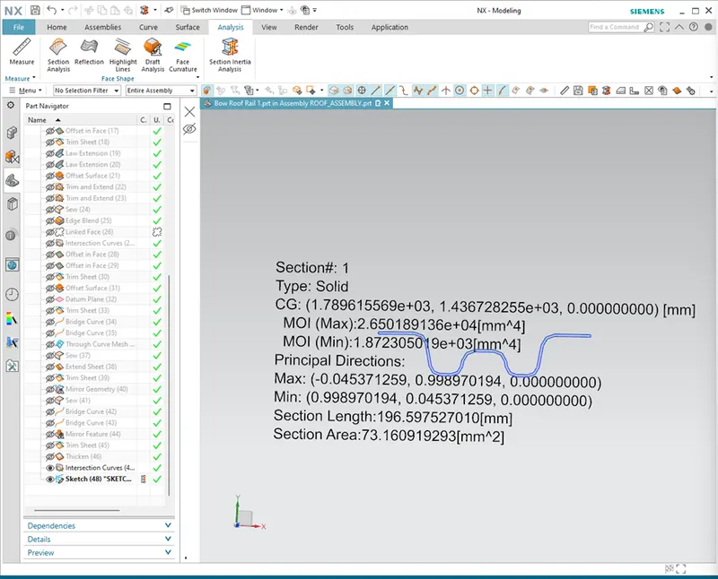
Iy = 1.872305019e+03
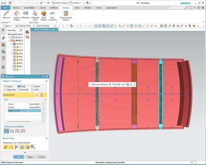
Lx = 1126.7568
Y = 617.1227
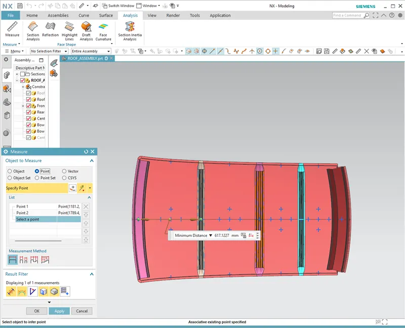
L1 = 617.1227
L2 = 570.5893
Rx = 4271.0676
Ry = 3023.911

For Case 2
Iy = 2.415703415e+03
Lx = 1074.4677
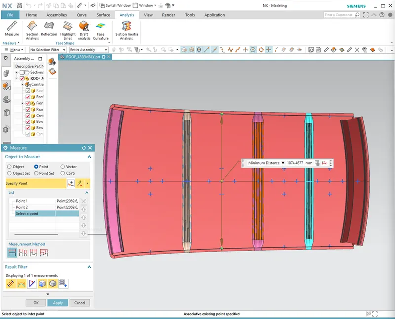
Y = 1183.5086
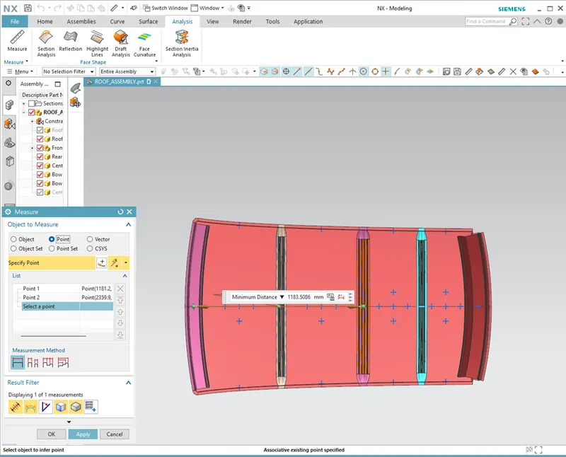
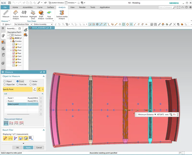
L1 = 570.5893
L2 = 407.8472
Rx = 3892.558
Ry = 7611.3726
For Case 3
Iy = 1.982810178e+03
Lx = 1051.6071
Y = 1588.4402
L1 = 407.8472
L2 = 402.4437
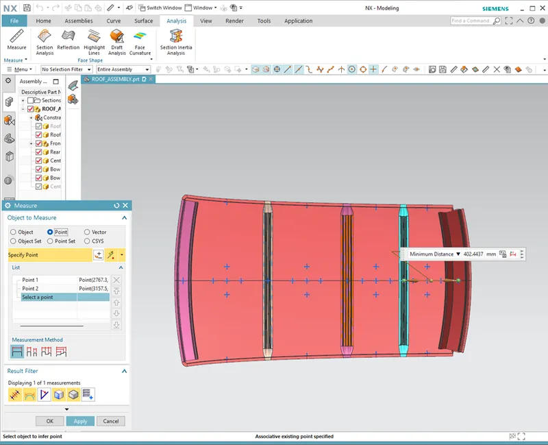
Rx = 4339.7956
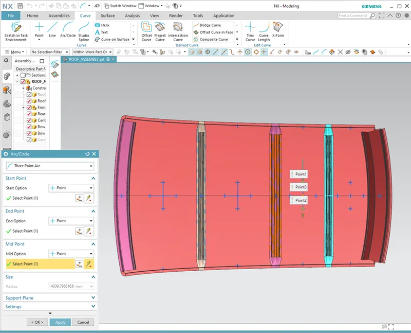
Ry = 12754.7289
FINAL RESULTS OF SNOW LOAD CRITERIA:
We have the necessary values for finding the Snow load value(Qr):
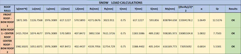
If roof structure pass to the snow load condition. They, must have Qr values from above 3.1.
Qr > 3.1
So, we done the curvature study on the roof. Heat distortion and snow load condition my roof is pass the two criteria, so position of the bow roofs and center reinforcement roofs placed at right area.
Manufacturing Techniques Used For making of Roof :
BLANKING : Blanking is a metal production process, during which a metal workpiece is removed from the primary metal strip or sheet when it is punched. The material that is removed is the new metal workpiece or blank.
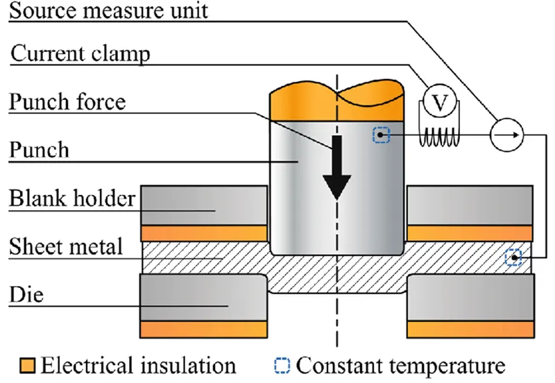
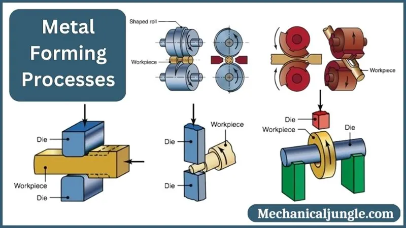
Forming : Forming is a mechanical process used in manufacturing industries wherein materials (mostly metals) undergo plastic deformations and acquire required shapes and sizes by application of suitable stresses such as compression, shear and tension.
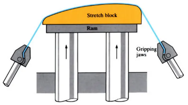
Stretch Forming : Stretch forming is a metal forming process in which a piece of sheet metal is stretched and bent simultaneously over a die in order to form large contoured parts. Stretch forming is performed on a stretch press, in which a piece of sheet metal is securely gripped along its edges by gripping jaws.
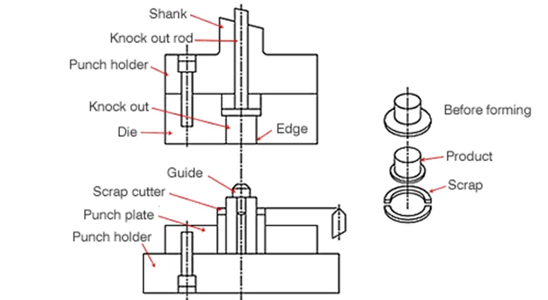
TRIMMING : The trimming process is the shearing of excess material from the headed configuration of complex shapes so as to obtain the final design and specifications.
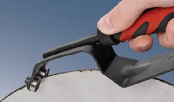
Deburring : The deburring tool that is used in the machines is the abrasive belt. Each belt has its own grit size, which is required for different types of burrs and alloys. A finer grit is recommended for softer alloys, whereas a rougher grit is best for alloys like steel.
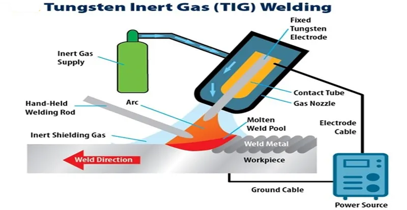
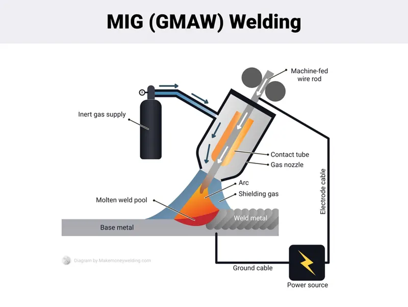
WELDING : The best welding processes for SHEET METAL are MIG and TIG. It is possible to stick weld on thin sheet metal, but it's harder to control the heat, it's messy and it's hard to master. Some welding machines also allow for pulsed MIG or TIG.
Spot Welding : Spot welding is a resistance welding process used primarily to weld two or more metal sheets together. It's called spot welding because this welding method creates a tiny dot weld, that looks like a spot.
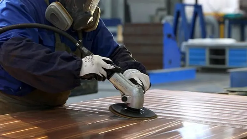
Grinding : Grinding for Precision Sheet Metal Fabrication is often a manual job to finish off to smooth welds, created unique lines, and finish rough edges. The goal is to remove small amounts of material in order to achieve a particular finish or tight tolerance. Most metal fabrication companies have a grinding machine
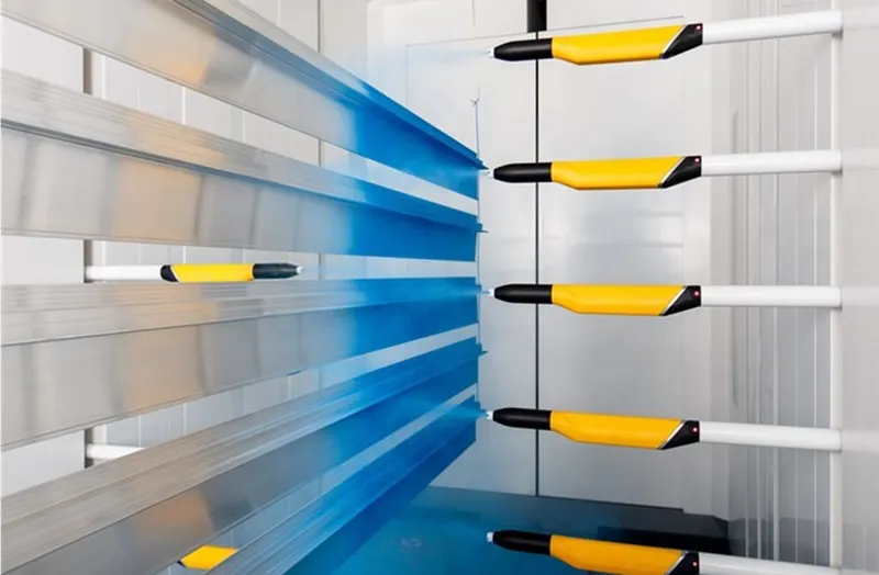
Painting : In painting sheet metal, the substrate is prepared for coating. Next, a primer is applied to the base metal, followed by multiple layers of paint. Finally, a protective coating, such as lacquer is added to protect the underlying paint.
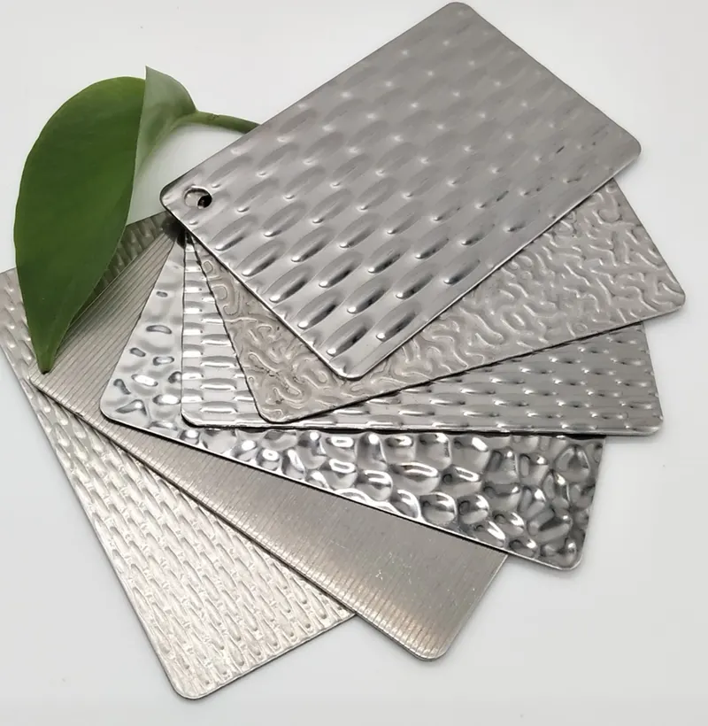
Embossing : Sheet metal embossing is a stamping process for producing raised or sunken designs or relief in sheet metal.The metal sheet embossing operation is commonly accomplished with a combination of heat and pressure on the sheet metal, depending on what type of embossing is required. Theoretically, with any of these procedures, the metal thickness is changed in its composition.
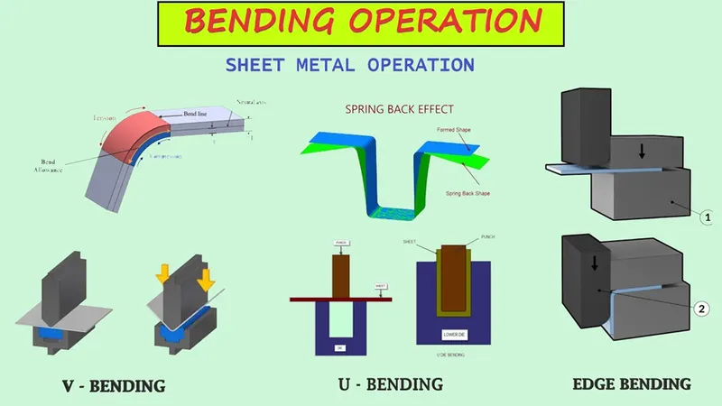
Bending : The sheet metal bending process involves applying a force to a sheet metal part to change its geometry. This force causes stress on the sheet metal beyond its yield strength, causing the material to physically deform without breaking or failing. The press brake is a commonly used tool to bend sheet metal.
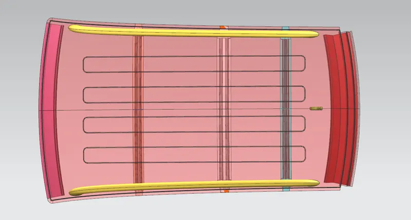
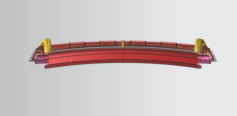
Roof Views :
Front View
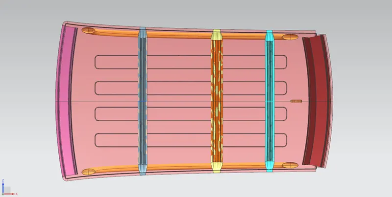
Top View
Back View
Right Hand Side View
Conclusion :
We have studied
- Design a Roof with its components by following the master section of the front roof rail with all the design parameter.
- Perform Draft Analysis.
- Do the curvature study on the roof based on the Bow roof prediction calculation.
- Manufacturing techniques.
With this we can conclude the roof have passed the heat distortion and snow load criteria and all parts are made as per master section parameters.
Therefore the roof can be placed on the car.