Roof Design
DESIGN OF ROOF AND CURVATURE ANALYSIS
ROOF ANALYSIS :
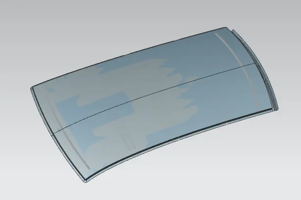
- The primary objective of a roof is to prevent the ejection of passengers, protection against hard local contact and various environmental conditions like heat, snow, rain etc.
The roof panel serves as a connectio
n of body sides, front, and rear roof members.
- Steel sheets of thickness in the range of 0.70 to 0.85 mm are used conventionally for construction of the roof.
OBJECTIVES :
-
For the Given Roof styling, Develop the essential flanges and reinforcements.
-
Provide appropriate dimension and check for Draft analysis and perform section modulus analysis on the 0-Y section.
-
Do a curvature study on the roof and perform calculations to determine the position of the Bow-roof.
ROOF OF AN AOTOMOBILE :
Types of roof reinforcements are as follows:-
- Front roof rail reinforcement (FR)
- Centre roof rail reinforcement (CR)
- Bow roof 1 rail reinforcement (BR1)
- Bow roof 2 rail reinforcement (BR2)
- Rear rail enforcement (RR)
FRONT ROOF RAIL REINFORCEMENT
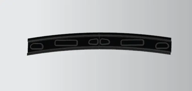
- It is the support that is joined with the windshield glass, bodyside outer and the inner panels.
- It is usually made from body side outer scrap and therefore the thickness of the rail is 0.65 mm.
- A draft angle of 3-5 degrees is provided for deep-drawing operation.
- The visibility criteria and the headroom clearance of the passenger are taken into consideration for the bottommost flange.
- Windshield end and the roof end are spot welded and the other end of the front roof rail is joined with the roof using mastic sealants for increased strength.
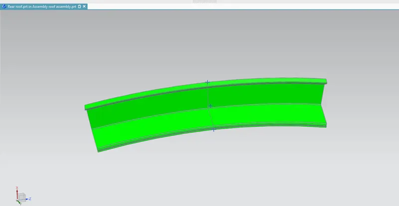
REAR ROOF RAIL REINFORCEMENT
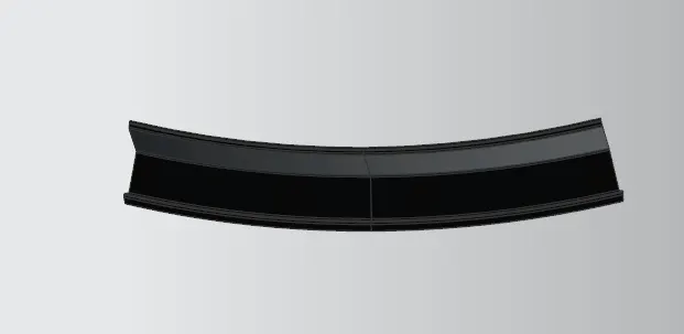
- It is the support that is joined to the backdoor, the bodyside outer and the inner panels.
- Inputs from the backdoor design is also taken to accommodate the required clearance along with headroom clearance and the rear visibility criteria while designing the rear roof rail.
- Spot welds are applied at the backdoor end of the rail and the other end is joined with the roof using mastic sealants.
CENTER ROOF AND BOW ROOF 1,2 RAIL REINFORCEMENT
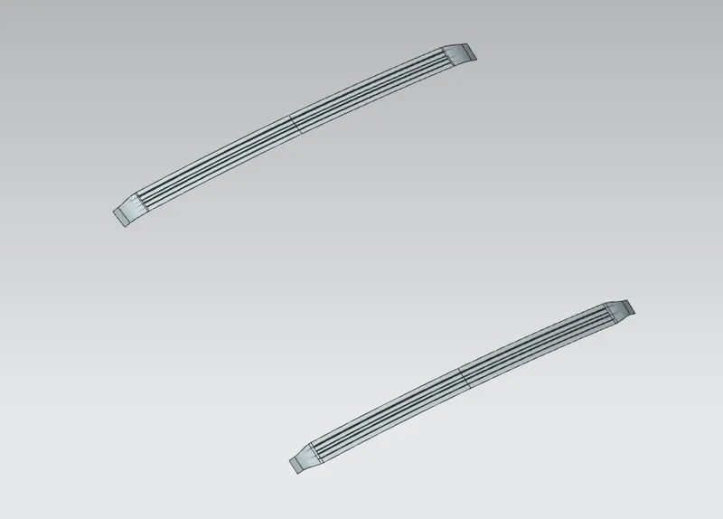
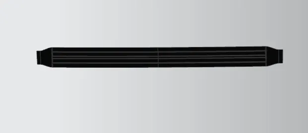
- Similar to other rail designs, we have to take into consideration the headroom clearance and the visibility criteria while designing the centre roof rail and bow roofs.
- Unlike the front and rear roof rails, spot welds are not applied for joining these rails to the roof.
- Mastic sealants are introduced at both the ends instead of spot welds since centre roof rail and row roofs are fully positioned under the styling surface of the roof.
HEAT DISTORTION CRITERIA
In this criteria to check the roof capacity with temperature and a fixed load.
so to calculate whether the roof deform or not, according to the position of the bow we do these calculations as follows
W = [1.73 x 10^(-3) x L] + [1.85 x 10^(-8) x (R^2)/t] + [ 1.10x10^(-3) x l] - 2.68
Where,
L = Roof Length in X-Direction[mm](Roof dimension in 0-Y)
R = Roof curvature
R = 2(Rx*Ry)/(Rx+Ry)
Rx = X curvature
Ry = Y curvature
t = Roof plate thickness [mm]
l = Bow Roof Span [mm]
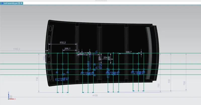
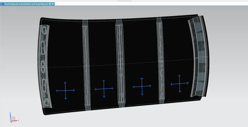
CALCULATION:
For the front roof rail and bow 1
Rx= 2656.35mm
Ry= 5731.56mm
R = 2(Rx*Ry)/(Rx+Ry)
R = 2(2656.35*5731.56)/(2656.35+5731.56)
R = 3630.23mm
l = 401.79mm
L = 2116.55mm
t = 0.75mm
Putting all values in the equation,
W = [1.73 x 10^(-3) x L] + [1.85 x 10^(-8) x (R^2)/t] + [ 1.10x10^(-3) x l] - 2.68
W = [1.73 x 10^(-3) x 2116.55] + [1.85 x 10^(-8) x (3630.23^2)/0.75] +
[1.10x10^(-3) x 401.79] - 2.68
W = 1.74
The condition for the heat distortion criteria is W>2.7 so the given is less than 2.7 so the position of the bow 1 is correct according to the hear distortion criteria.
we do the calculation for the remaining Bows positions as shown in the following table,
| ROOF RAIL | Rx(mm) | Ry(mm) | Rx*Ry(mm) | Rx+Ry(mm) | R(mm) | L(mm) | t(mm) | l(mm) | W | RESULT |
| FR-BOW1 | 2656.35 | 5731.56 | 15225029 | 8387.91 | 3630.23 | 2116.55 | 0.75 | 401.79 | 1.74 | PASS |
| BOW1-CENTER | 6342.64 | 4935.13 | 31301752 | 11277.77 | 5551.05 | 2116.55 | 0.75 | 339.74 | 2.11 | PASS |
| CR-BOW2 | 10342.39 | 4023.60 | 41613640.4 | 14365.99 | 5793.35 | 2116.55 | 0.75 | 419.85 | 2.27 | PASS |
| BOW2-RR | 14392.26 | 3309.02 | 47624276.19 | 17701.28 | 5380.88 | 2116.55 | 0.75 | 374.52 | 2.10 | PASS |
SNOW LOAD CALCULATION
- This snow load condition calculation is done to check the strength of the roof when there is dead weight on the roof.
- As we know that in some regions we have snowfalls so when snow falls on the roof then this act as dead weight because in some the rate of snowfall is more so the roof should sustain this dead weight for that we do this calculation to check the position of the bow and its sectional area.
The formula for snow load condition:
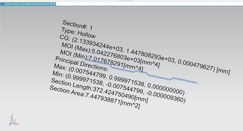
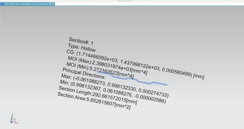
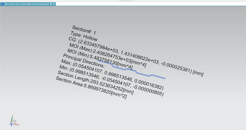
Qr = [Iy x t2] / [α x s x [(Rx + Ry)/2]2 x 10-8]
α = My x Lx2 x 10-12 , My = Y(Ly-Y)
t = Roof plate thickness [mm]
Ly = Distance between the front and rear roof Rails on the Vehicle along with 0Y[mm]
Length of Roof panel with the center point between Roof rail Front /Rear as the front and rear reference point.
Lx = Distance between the Left and Right end of the roof on the Roof BOW [mm]
The width of the roof panel is exposed on the surface.
Y = Distance front Front Roof Rail to Roof BOW[mm]
s = Distance for which Roof BOW bears divided load [mm]
s = L1/2 + L2/2
Iy = Geometrical moment of inertia of Roof BOW (Y cross-section )[mm4]
Rx = Lateral direction curvature radius of roof panel Y cross-section on Roof BOW [mm]
Roof panel curvature Radius of the Length Lx in Front view
Ry = Longitudinal Direction curvature radius of the Roof panel X cross-section on Roof BOW [mm]
Roof panel X curvature radius of length s in Side view
FOR CENTER ROOF RAIL
FOR BOW1
FOR BOW ROOF 2
CALCULATION
For front roof rail and Bow1:
Iy = 5273.1mm^4
Y = 443.78mm
My = Y(Iy−Y)
My = 443.78(5.2731-443.78)
My = 233985
Lx = 1041.51
α = My⋅Lx^2⋅10^−12
= 233985* 1041.51^2*10^-12
= 0.25
S = L1/2 + L2/2
= 443.78/2+339.74/2
S = 391.76
t = 0.75mm
Rx = 4414.50mm
Ry = 2773.98mm
Qr = [Iy x t2] / [α x s x [(Rx + Ry)/2]2 x 10-8]
= [5273.1 x 0.75^2]/[0.25 x 391.76 x [(4414.50+2773.98)/2]^2 x 10^-8]
= 26.30
Judgemental criteria is QR>3.1
| ROOF RAIL | ly | My | Lx | Ly | Y | S | Rx | Ry | t | Qr | RESULT |
| FR-BOW1 | 5273.1 | 233985 | 1041.51 | 1955.40 | 423.78 | 381.76 | 4414.50 | 2773.98 | 0.75 | 27.30 | PASS |
|
BOW1-CR |
7017 | 15785 | 1041.51 | 1955.40 | 369.54 | 426.53 | 11784.42 | 3771.16 | 0.75 | 14.56 | PASS |
| CR-BOW2 | 5483 | 235675 | 1041.51 | 1955.40 | 472.59 | 580.3 | 10790.61 | 3224.25 | 0.75 | 26.10 | PASS |
Joining Method used for manufacturing of Roof:
1.Spot welding points:
2.Mastic Points:
Position of these points on Roof
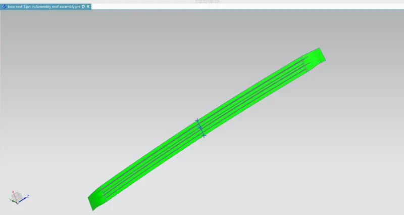
Draft analysis to check the manufacturability of roof and its parts:
BOW ROOF 1
BOW ROOF 2
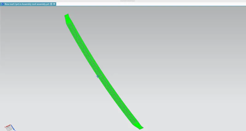
FRONT ROOF
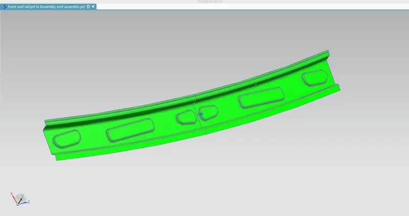
CENTER ROOF
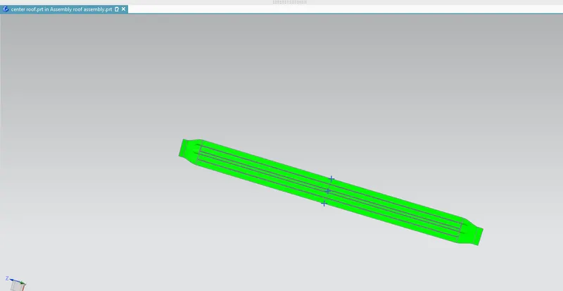
REAR ROOF