Roof Design
ROOF DESIGN
Objective:-
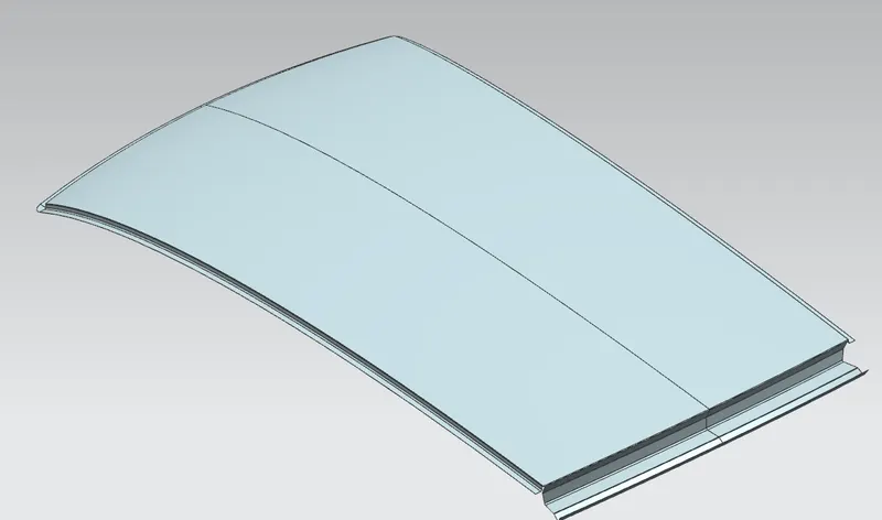
The main objective of this project is to design car roof panel with essential flanges and reinforcements.
Also to do the draft analysis for each reinforcement.
Software Used:-
NX 12
Car Roof:-
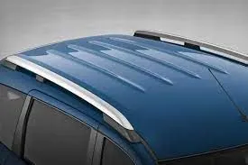
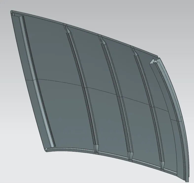
Roof is the top most covering provided for the vehicle and for safety side it’s important for roll over kind of accidents, which the basic test performed for safety purpose. In order to give strength, it is provided with embosses on top of the roof.
Thickness of components - 0.75 mm
Manufacturing Techniques-
1. Curling-
Curling is sheet metal forming process. Sheet metal are contains the sharp edges and burr after in initialy produced. Curling is the deburring of sharp edges to produce smooth edges.

2. Bending -
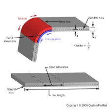
Bending is the forming process. The sheet metal is placed over a die block at which point a punch presses down onto the sheet metal.Companies typically perform bending on sheet metal by using either a brake press or similar press machine.
3. Punching-
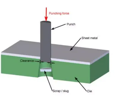
Punching is a sheet metal forming process. It involves the punch and die set to create holes in sheet metal. The sheet metal is placed between the punch and die. The punch is presses down through the sheet metal to create a hole.
4. Sharing-
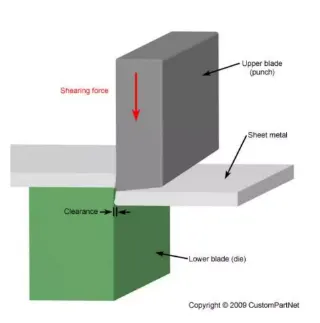
Shearing is define as seperating material into two parts. It utilizes shearing force to cut the material.
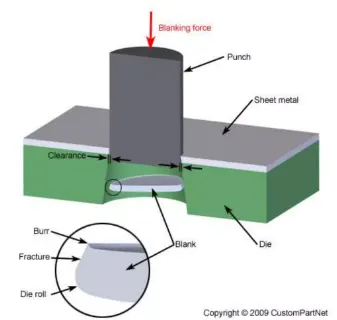
5. Blanking-
Blanking is a shearing process. A piece of sheet metal is remove from larger piece of stock. This remove piece is not a scrap, it is a useful part.
6. Piercing-
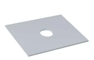
Piercing is a shearing process. In this process raw material is pierced with the help of machine tools. As the raw metal is pierced, the metal from the newly created hole is considered scrap.
Types of Reinforcements used in roof design:-
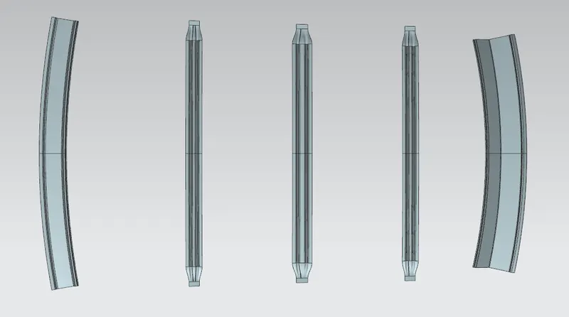
1. Front Roof Rail
2. Rear Roof Rail
3. Center Roof Rail
4. BOW Roof Rail
1. Front Roof Rail-
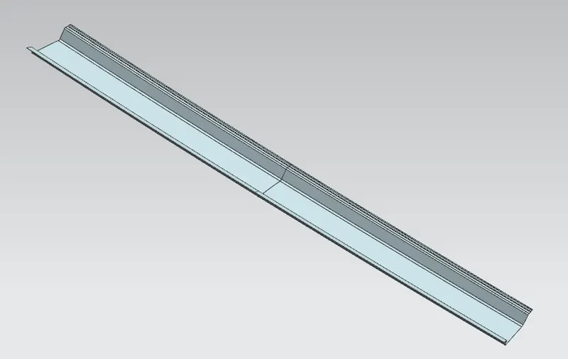
Front roof rail is the reinforcement which is use at front side of roof. this joins the wind shield glass, This is the front roof rail design by following master section.
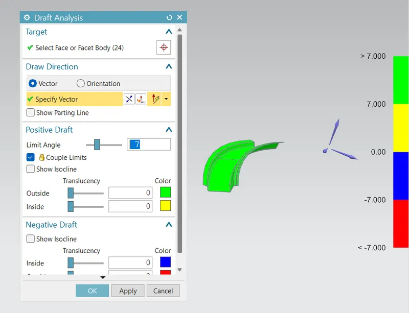
Draft Analysis-
Draft analysis is done considering the draft angle of 7 degree.
2. Rear Roof Rail
Rear roof rail is the one which joins the back door and body side outer.
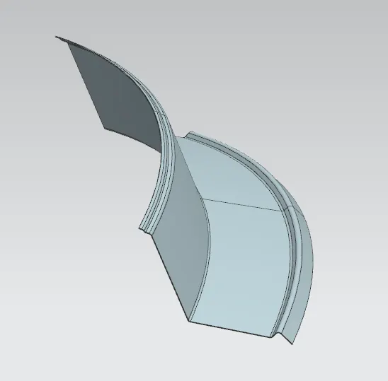
Draft Analysis-
Draft analysis is done considering the draft angle of 7 degree.
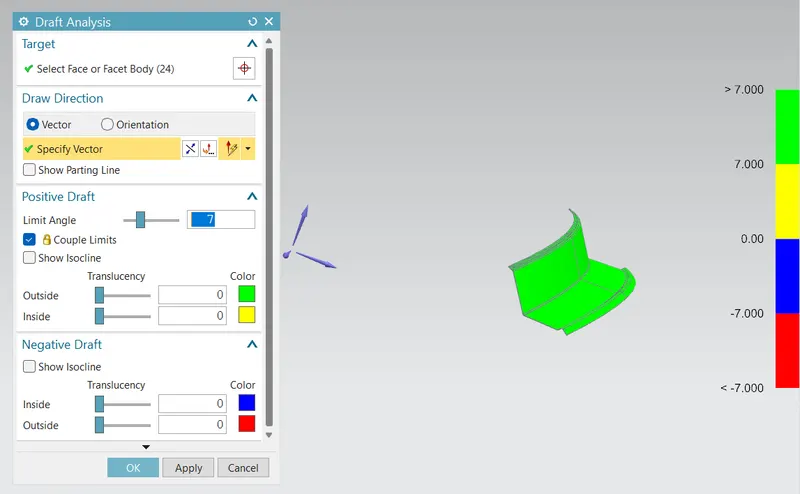
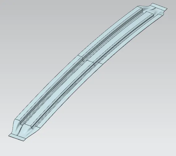
3. Centre Roof Rail -
Centre roof rail has two layers(reinforcement) as to protect it from roll over crash.
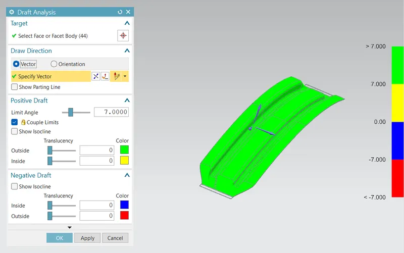
Draft Analysis-
Draft analysis is done considering the draft angle of 7 degree.
4. BOW Roof Rail-
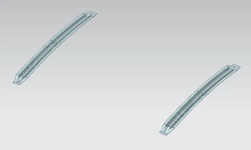
Bow roof rails are provided for the support of the roof surface.
The bow roofs are provided with mastic sealant as they are assembled with the surface as welding is not possible, whereas
the ditch area, front and rear area is welded with the roof.
Bow roof 1 and bow roof 2 are provided for better protection of roof from crash.
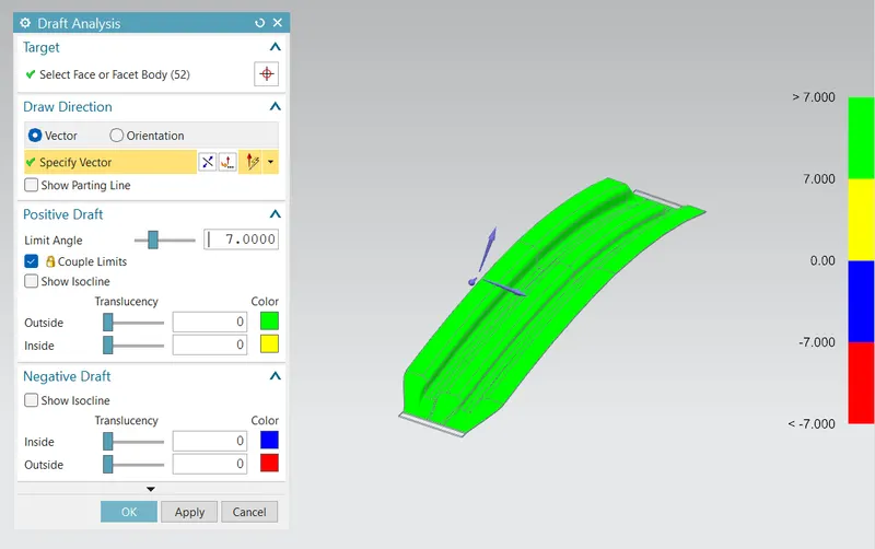
Draft Analysis-
Draft analysis is done considering the draft angle of 7 degree.
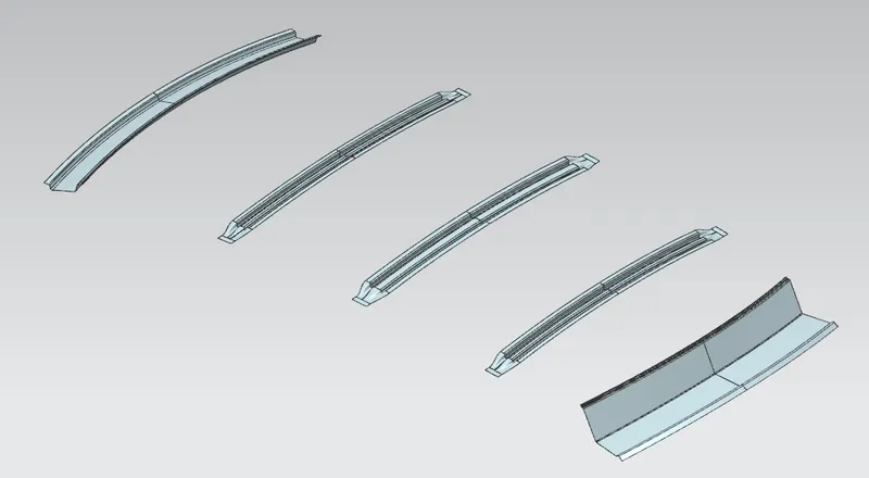
Roof reinforcements image-
Design Considerations For Roof:-
- Visibility criteria
- Head clearance
- Curvature study
- Heat distortion and snow load criteria
- Draft analysis
ROOF CRUSH TEST :
Roof crush test is the design given by ( insurance institute of highway safety ) IIHS . After analysing so many accidents IIHS has fixed some regulations , that how to perform the crush test .
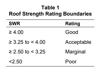
IIHS gives the rating based up on this test called Srength To Weight Ratio (SWR) .
Force and displacement data are recorded for 5 seconds prior to each test, while the test system holds the loading platen at initial roof contact. The data recorded from 1 to 4 seconds of this hold time are averaged for each channel to produce a measurement offset that is subtracted from the data recorded during the
crushing of the roof.
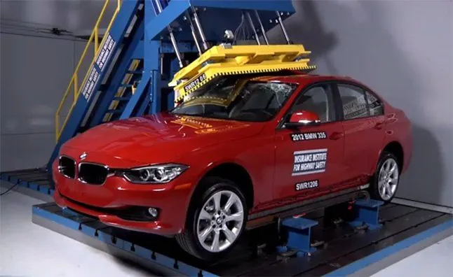
The maximum force prior to 127 mm of platen displacement is divided by the measured curb weight to obtain the SWR. Both the force and curb weight are rounded to the nearest pound prior to performing the
calculation, and the resulting SWR is rounded to the nearest one-hundredth of a unit. Displacement is rounded to the nearest 0.1 mm. (The maximum displacement where the load can be used for the vehicle
rating is 126.9 mm.) The vehicle’s rating is assigned based on the boundaries listed in Table 1.
There are two conditions while performing the crush test
1. First Condition-
Close and lock all the doors
Close all the windows.
2. Second Condition-
Fix the body sill or chassis frame on a hard lever surface horizontally
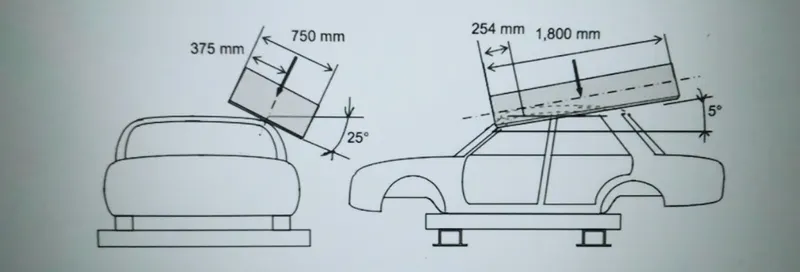
Roof strength evaluations are conducted on a quasi-static test system manufactured by MGA Research Corporation
The system consists of an upright assembly and an attached loading head that can be fixed at varying heights from the ground and at pitch angles ranging from −5 to +5 degrees to accommodate testing on the
driver or passenger side.
The roll angle is permanently fixed at 25 degrees.
Four hydraulic actuators control the movement of the platen along two linear guides.
The entire system is mounted on a T-slot bed plate anchored to the floor of the test facility.
A] Checking of heat Distortion Criteria -
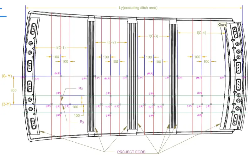
It is the temperature at which the material starts softening when exposed to a fixed load at elevated temperature.
Above this temperature the material can’t be used.
In order to know whether the material is in safer zone according the positioning of bow roofs, the test is performed by considering the below given formula -
W = [1.73 × 10^-3 × L] + [1.85 × 10^-8 × ((R^2)/t)] + [1.10x10^-3 × l] - 2.68
R = 2(Rx X Ry) ÷ (Rx+Ry)
L = Roof Length in X-Direction [mm] (Roof dimension in 0-Y)
R = Roof curvature
Rx = X curvature
Ry = Y curvature
t = Roof plate thickness [mm]
l = Bow Roof Span [mm]
Judgment Condition: OK<2.7mm<NG
Results obtained –
| Sr.No. | Roof Rail | Rx(mm) | Ry(mm) | R(mm) | t(mm) | L(mm) | I | W | w<2.7 | Result |
| 1 | BOW Roof Rail 1 | 5692.2474 | 3010.6381 | 3938.3022 | 0.75 | 2064.9407 | 518.4453 | 1.84 | 1.84<2.7 | Pass |
| 2 | Centre Roof Rail | 4724.5500 | 7190.3145 | 5702.2889 | 0.75 | 2064.9407 | 390.8853 | 2.12 | 2.12<2.7 | Pass |
| 3 | BOW Roof Rail 2 | 3842.4492 | 11276.0088 | 5731.7341 | 0.75 | 2064.9407 | 390.8941 | 2.13 | 2.13<2.7 | Pass |
| 4 | Rear Roof Rail | 3242.5012 | 14831.2212 | 5321.5659 | 0.75 | 2064.9407 | 288.9146 | 1.90 | 1.90<2.7 | Pass |
So as per the results obtained the roof is safer zone as the W values are below 2.7 as per the standard condition.
Thus the design passes the Heat Distortion Test.
B] Snow Load Prediction Formula-
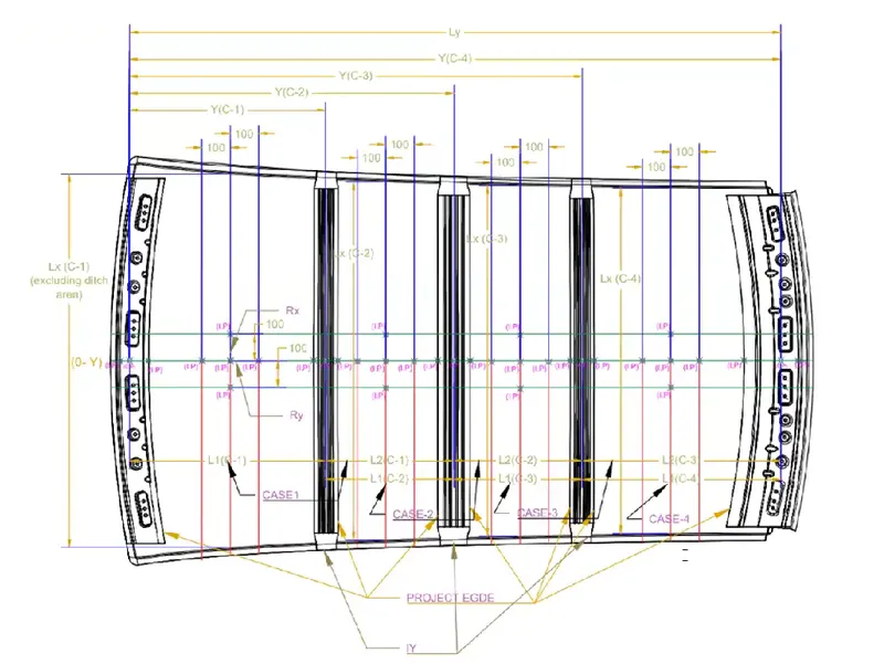
Qr = [Iy x t2] / [α x s x [(Rx + Ry)/2]2 x 10-8]
Where,
α = My x Lx2 x 10-12 , My = Y(Ly-Y)
t = Roof plate thickness [mm]
Ly = Distance between the front and rear roof Rails on the Vehicle along with 0Y[mm]
Length of Roof panel with the center point between Roof rail Front /Rear as the front and rear reference point.
Lx = Distance between the Left and Right end of the roof on the Roof BOW [mm]
The width of the roof panel is exposed on the surface.
Y = Distance front Front Roof Rail to Roof BOW[mm]
s = Distance for which Roof BOW bears divided load [mm]
s = L1/2 + L2/2
Iy = Geometrical moment of inertia of Roof BOW (Y cross-section )[mm4]
Rx = Lateral direction curvature radius of roof panel Y cross-section on Roof BOW [mm]
Roof panel curvature Radius of the Length Lx in Front view
Ry = Longitudinal Direction curvature radius of the Roof panel X cross-section on Roof BOW [mm]
Roof panel X curvature radius of length s in Side view
Judgment condition
Qr ≥ 3.1
250 ≤ s ≤ 380
Results obtained –
| Sr.No. | Roof Rail | Rx(mm) | Ry(mm) | Lx(mm) | Ly(mm) | L1(mm) | L2(mm) | s(mm) | Y | My | α | t(mm) |
Iy(mm4) |
Qr | Qr≥3.1 | Result |
| 1 |
BOW Roof 1 |
4271.39 |
3023.28 | 1127.82 |
1975.94 |
614.62 | 468.55 | 541.58 | 614.62 | 836694.49 | 1.06 | 0.75 | 1.83 | 13.5 | 13.5≥3.1 | Pass |
| 2 | Centre Roof Rail | 3843.40 | 7159.52 | 1078.59 | 1975.94 | 468.55 | 468.51 | 468.53 | 1079.71 | 967668.49 | 1.12 | 0.75 | 1.94 | 6.9 | 6.9≥3.1 | Pass |
| 3 | BOW Roof 2 | 11950.59 | 4323.95 | 1055.22 | 1975.94 | 468.51 | 445.21 | 456.86 | 1544.89 | 665924.83 | 0.74 | 0.75 | 1.84 | 4.6 | 4.6≥3.1 | Pass |
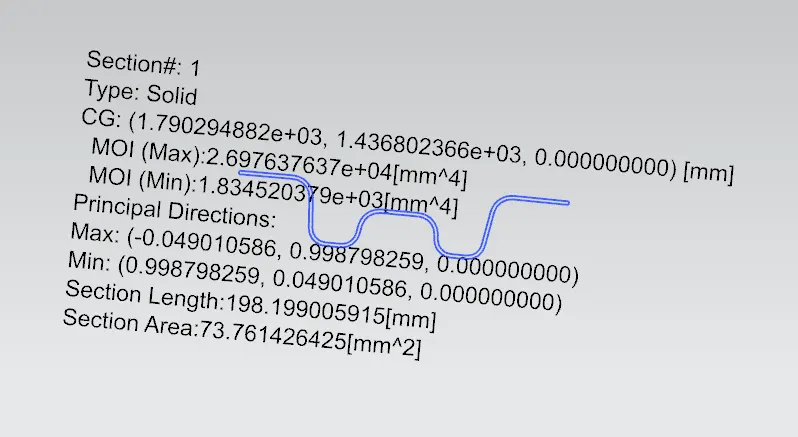
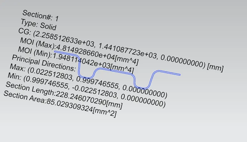
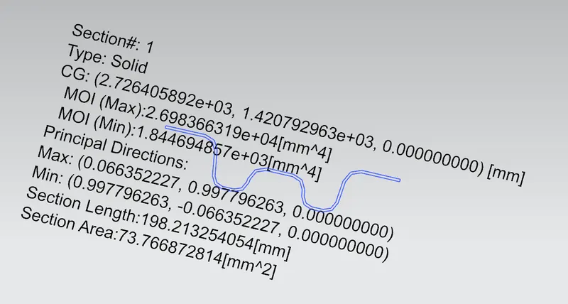
Section Inertia Analysis -
1. BOW Roof 1-
2. Centre Roof Rail-
3. BOW Roof 2-
Conclusion-
Hence the Roof, Front Roof Rail, BOW Roof 1, Centre Roof Rail, BOW Roof 2, Rear Roof Rail is created by following master section and design considerations.
Draft analysis is carried out to check component feasibiliy for manfacturing.