Roof Design
ROOF DESIGN
Objectives:
Get the Roof outer panel skin data Analysis for Bow roof rail & center roof rail postion and also where place that possion and same time analayis for Section modulus &Heat disortion Analayis & snow load analayis .
Roof Design:
A roof of a car consists a outer skin panel which is designed with aesthetics and aerodynamics in mind and the support structure of the panel. In case of passenger cars the roof is designed to be flexible enough to regain its original shape after smaller loads due to snow of light impacts are applied to it. At the same time the roof needs to withstand all the impact forces and self weight in a roll over incident. Hence the support structure is a vital part of the roof design. Usually it consists of a Front roof rail, a rear roof rail, center roof rails &Bow 1 &Bow 2
The front and rear roof rails are used to join the roof with the rest of the BIW of the car along with front windshield, dampening components, sealants etc. Roof reinforcement panel is provided where the roof is flatter usually in the middle along the length of the car again to provide strength to the roof. Bow roof rails are provided as and when necessary, and are attached to the roof panel using mastic sealants. The longer the roof, more the number of bow rails. The dimensions of the support structure like the depth and length which will affect the front and rear visibility, interior design and material required, headroom and overall space it will occupy is governed by ergonomics and region specific regulations where the car is to be sold.
Analayis:
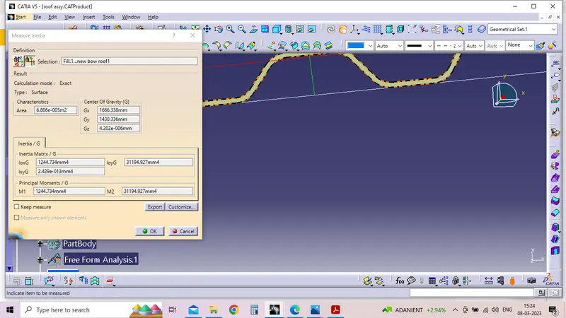
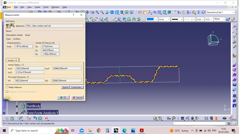
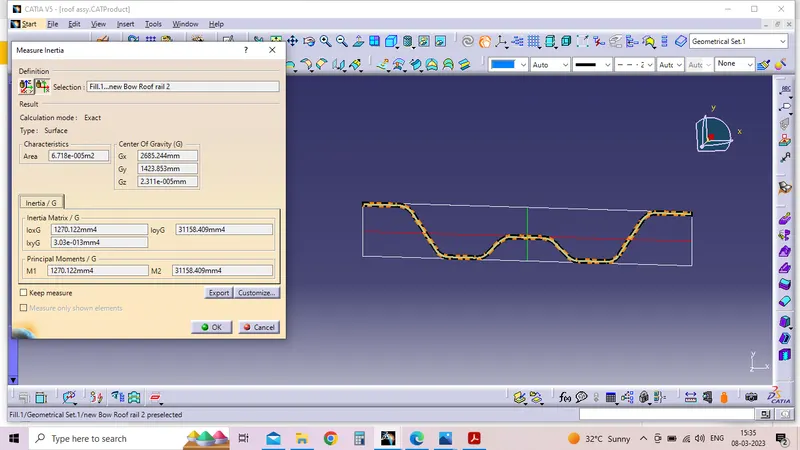
Section Modulus for BOW ROOF Rail 1& BOW roof rail 2,Front roof rail,rear roof rail, Center roof rail. also below attched
Draft analayis:
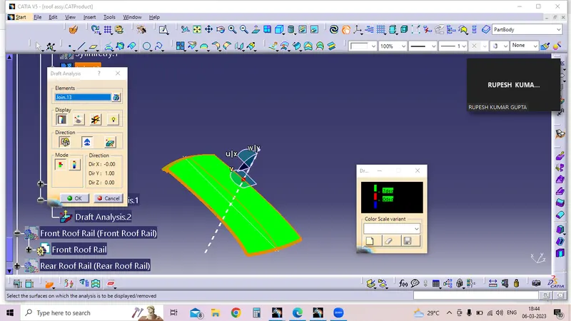
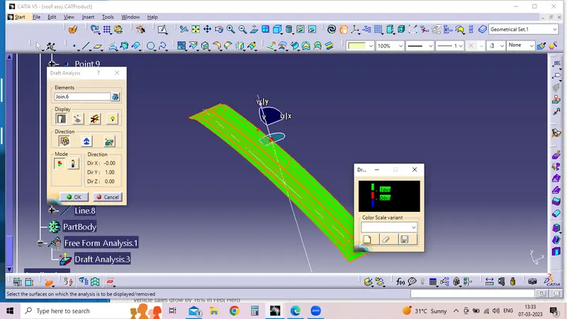
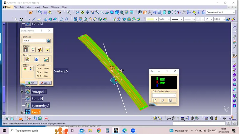
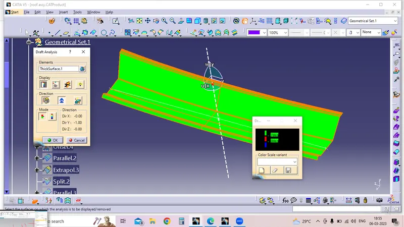
Roof skin panel and also the Roof assy parts are Manufactring form mostly Stamping Panel so we are proforming tooling direction so we are analayis for tooling Direction after Draft directions. some of Draft anayis attached below.
Heat disortion Analayis;
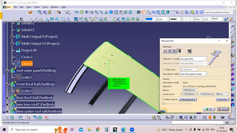
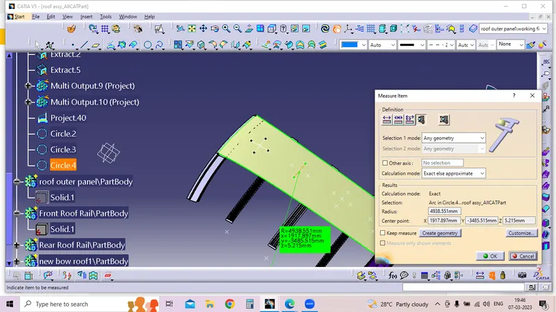
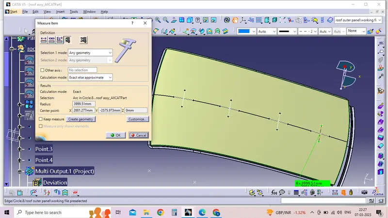
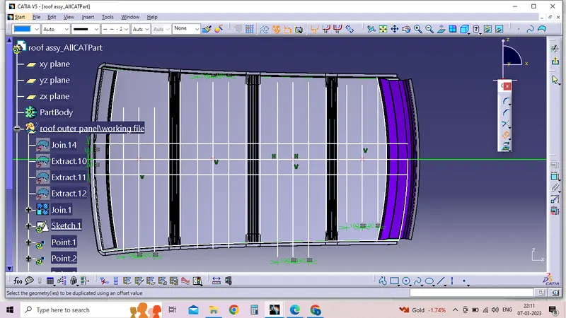
After completeing the design of roof draw the 0-y line after that -300 -y line fix and also that line offset both side 100 mm and same time Fr -bow1,Bow1- Cen roof rail,Cen roof rail to Bow 2,Bow 2 -Rear roof rail , mid point fix after draw the line that mid point that line also offset bothside 100mm after that intersection points on -300-Y line and also offset lines.That intersection points projected on the outer most skin panel projected points connected with 3d arc that arc measured that vale RX, Ry value identifed
Snow load Analayis;
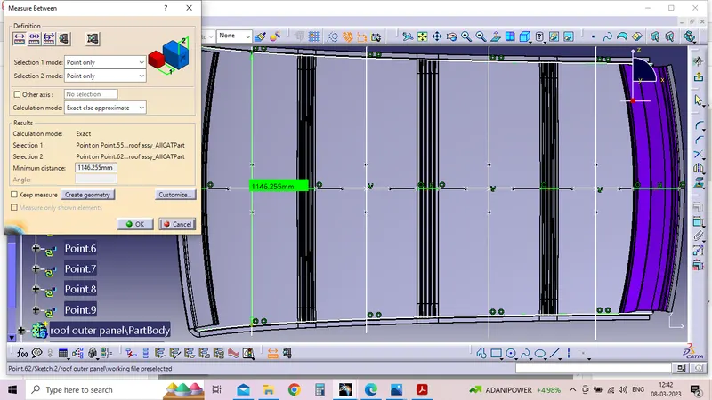
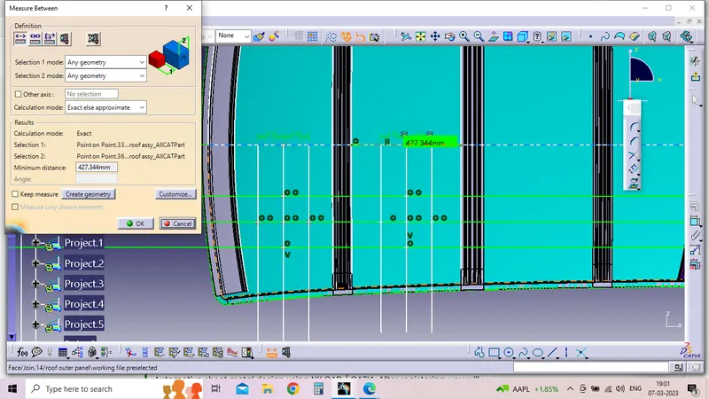
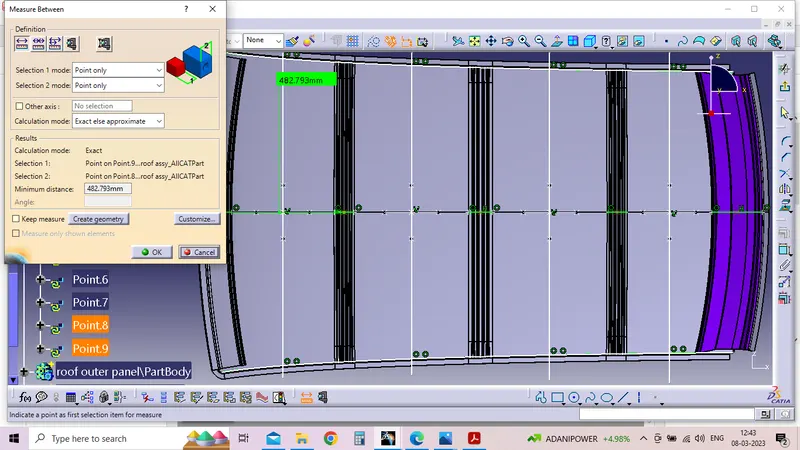
After completing the Roof design process draw the 0-y line that line offset both side 100 after that intermid points of FR-BOW 1,Bow 1-Center roof ,Center roof -Bow 2,Bow 2- Rear roof rail idendified after draw the line through That mid point ,that line also offset both side 100 mm after draw the insection points projected on the outer most skin panel projected points connected by the arc that measured Rx,RY identified, LX value intermid line intersect with Before dich area line measure thevalue of inbetween the Intersection points.
Ly- Intermid point of FR roof Rail to Intermid point of RR roof rail
Bow–Roof Prediction Formula
W = [1.73 x 10^(-3) x L] + [1.85 x 10^(-8) x (R^2)/t] + [ 1.10x10^(-3) x l] - 2.68
Where,
L = Roof Length in X-Direction[mm](Roof dimension in 0-Y)
R = Roof curvature
R = 2(Rx*Ry)/(Rx+Ry)
Rx = X curvature
Ry = Y curvature
t = Roof plate thickness [mm]
l = Bow Roof Span [mm]
Judgment Condition
OK< 2.7
| Sectoin | RX (mm) | RY(mm) | RX+RY | R | L | T | l | W | RESULT |
| FR-BOW1 | 2580.982 | 5737.152 | 8318.13 | 3560.29 | 2032.35 | 0.75 | 382.399 | 1.56 | P |
| BOW1-CEN ROOF | 4938.551 | 6333.195 | 11271.74 | 5549.59 | 2032.35 | 0.75 | 427.344 | 2.06 | P |
| CEN ROOF- BOW 2 | 3948.64 | 10728.722 | 14677.3 | 5772.68 | 2032.35 | 0.75 | 427.475 | 2.12 | P |
| BOW2 -Rr Roof | 3275.35 | 14620.144 | 17895.5 | 5351.7 | 2032.35 | 0.75 | 348.281 | 1.92 | P |
Snow Load Prediction Formula
Qr = [Iy x t2] / [α x s x [(Rx + Ry)/2]2 x 10-8]
Note: The Qr value given over here is correct. There was a typo error in the formula given in the video.
Where,
α = My x Lx2 x 10-12 , My = Y(Ly-Y)
t = Roof plate thickness [mm]
Ly = Distance between the front and rear roof Rails on the Vehicle along with 0Y[mm]
Length of Roof panel with the center point between Roof rail Front /Rear as the front and rear reference point.
Lx = Distance between the Left and Right end of the roof on the Roof BOW [mm]
The width of the roof panel is exposed on the surface.
Y = Distance front Front Roof Rail to Roof BOW[mm]
s = Distance for which Roof BOW bears divided load [mm]
s = L1/2 + L2/2
Iy = Geometrical moment of inertia of Roof BOW (Y cross-section )[mm4]
Rx = Lateral direction curvature radius of roof panel Y cross-section on Roof BOW [mm]
Roof panel curvature Radius of the Length Lx in Front view
Ry = Longitudinal Direction curvature radius of the Roof panel X cross-section on Roof BOW [mm]
Roof panel X curvature radius of length s in Side view
Judgment condition
Qr ≥ 3.1
250 ≤ s ≤ 380
| Case | Iy | Lx | RX | RY | Y | S | @ | Qr | resut |
| FR- BOW1 | 1224.73 | 1146.2 | 4057 | 2634 | 482.7 | 496.1 | 0.931 | 13.46 | OK |
| BOW1 &Cen-BOW2 | 1622.224 | 1095.833 | 3771 | 6329 | 992.3 | 509.7 | 1.14 | 6.2 | OK |
| CEN &BOW -RR roof | 1270.122 | 1067.206 | 11278.9 | 4290.98 | 1502.406 | 479.419 | 0.76477 | 3.2 | OK |
conclusion;
Design process completion all the calculation done Section modulues,Heat dissortion ,Snow load condition also check all are ok. if addtionaly roof strength will maintain roof outerpanel embosess will create for more strenthen of roof outer panel.