Roof Design
Aim:
Utilizing the provided skin data for the roof in accordance with the standards for hear distortion and snow load, the front, rear, and bow roof rails for the cars' roofs are designed.
Objective:
- To change the position of the bows and the central roof rail, research the heat distortion criterion.
- To include roof design into the development of the necessary flanges and reinforcements.
- Study snow load circumstances to determine the strength of the roof based on the placement of the bows.
Introduction:
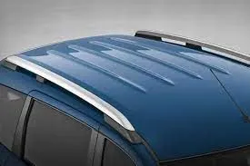
An essential component of an automobile, the roof covers the cabin and shields occupants from the outdoors. It acts as the upper barrier of the car's cabin and is normally found at the highest point of the vehicle. Car roofs may affect the overall design and aerodynamics of the vehicle as well as give structural support, protection from wind, rain, and other environmental variables.
Metal, plastic, glass, and fabric are just a few of the materials that may be used to construct car roofs. They can also be fixed, retractable, or convertible. Personal choice, environment, and the car's intended purpose are frequently factors in determining the style of roof that is selected.
In general, the roof of a car is an essential part of any vehicle, providing both functional and aesthetic functions.
Design consideration:
-
Visibility criteria
-
Head clearance
-
Curvature study
-
Hear distortion and snow load criteria
-
Draft analysis.
From designer's point of view, the design of a car roof is a complex process that takes into account a variety of factors, including safety, durability, aerodynamics, and aesthetics. Here are some key considerations for a roof designer:
-
Safety: The roof of a car must be designed to protect passengers in the event of a collision, rollover, or other accident. This requires the use of strong, lightweight materials and the implementation of crash-resistant features, such as reinforced pillars and roof rails.
-
Durability: The roof of a car must be able to withstand harsh weather conditions and regular use over time. This requires the use of materials that are resistant to rust, corrosion, and UV damage, and the implementation of a design that will prevent leaks and other types of wear and tear.
-
Aerodynamics: The roof of a car can have a significant impact on the overall aerodynamics of the vehicle, which can affect fuel efficiency, stability, and handling. Roof designers must consider the shape, thickness, and material of the roof in order to minimize wind resistance and improve aerodynamics.
-
Aesthetics: The roof of a car is an important aspect of its overall appearance, and roof designers must consider the overall style of the vehicle when designing the roof. Roof design can also play a role in the functionality of the car, with some roofs featuring integrated sunroofs, T-tops, or panoramic views.
Overall, a roof designer must balance these factors in order to create a roof that is both functional and aesthetically pleasing. The end result is a crucial component of the car that serves both practical and aesthetic purposes.
Reinforcement of Roof:-
- Front Roof
- Rail Bow Roof
- RailCenter Roof Rail
- Rear roof Rail
Manufacturing Techniques:
By outer board machining process, bar-shaped assembly, ring-shaped component processing, and roof cant rail processing technology formed respectively.
Outside plate process: the first step, open the straight snips plate: first select the applicable cold coiling specification, and cold coiling is opened flat; Then according to the production material specification, will open cold coiling after the flat and is cut into the iron plate of the corresponding size; Finally the iron plate after shear is cleaned to iron filings; The first step, oil pressure, punch press: the first iron plate is extended; Secondly to its trimming and punching; Then to its flanging and punching; Finally, after punching completes, it is carried out to the operation of side folding; Completed the making of the outside plate.
Bar-shaped assembly and ring-shaped component process: the first step, blanking, stamps out an iron plate with the outline blank of many roof cant rails, a ring-shaped component, and a bar-shaped assembly; the Second step, carries out annular punching to ring-shaped component; Bar shaped assembly and roof cant rail are carried out to bar-shaped punching.
Car roof anabolic process: the first step, is by a plurality of M6 nuts of a side spot welding of the ring-shaped component; By two M6 nuts of the bar-shaped assembly two ends spot welding; the Second step, spots weld bar shaped assembly the opposite side of the corresponding nut of the ring-shaped component; And circular groups and the punching of bar-shaped assembly are aimed at; The 3rd step, is welded to ring-shaped component the inner side of the outside plate; The 4th step, spots weld roof cant rail the inner side of the outside plate; Finally car roof integral body is carried out to sanding thorn and ending.
1. Design a Ditch Area for Outer Roof Panel:
- Front Ditch Area:
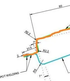
Fig:1.1 Front Ditch Area Master Section.
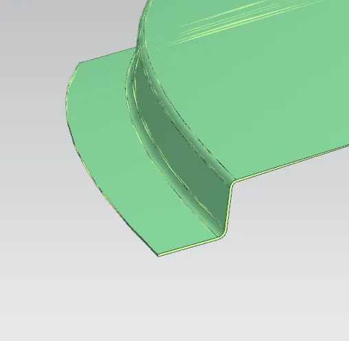
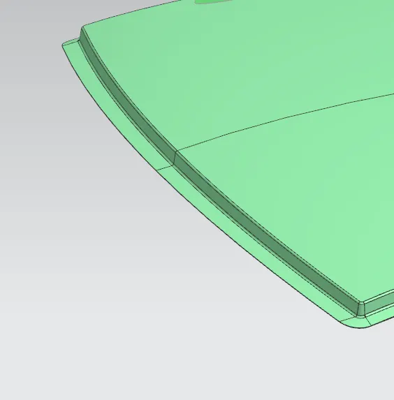
Fig:1.2 Front Ditch Area of Outer Roof Panel.
- Rear Ditch Area:
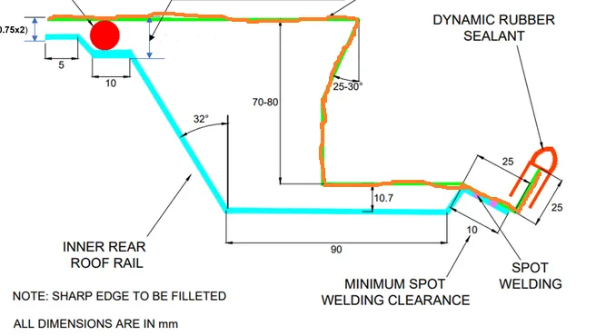
Fig:1.3 Rear Ditch Area Master Section.
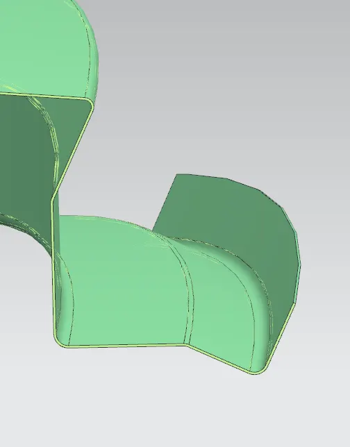
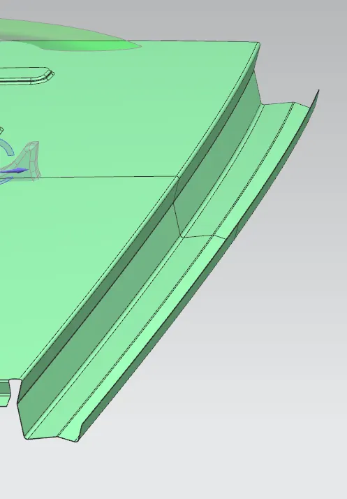
Fig:1.4 Rear Ditch Area of Outer Roof Panel.
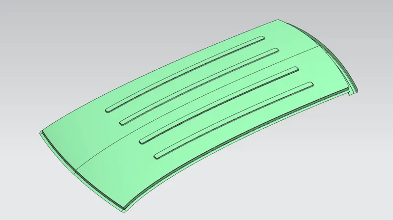
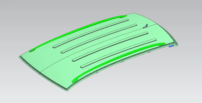
Fig:1.5 Completed Outer Roof Panel with Front, Rear, and Side Ditch Area.
2.Design of Front Roof Rail:
This is the frontal reinforcement offered. This component is attached to the windscreen and BIW body. When connecting it to the windscreen, visibility requirements are taken into consideration. Spot welds are used to secure it to the BIW, and mastic sealants are used to fasten the roof surface. The operation of deep drawing is given with a draught angle. The portion also undergoes a draught study to determine its production capacity.
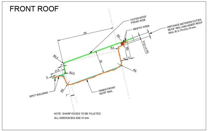
Fig:2.1 Front Roof Rail Master Section.
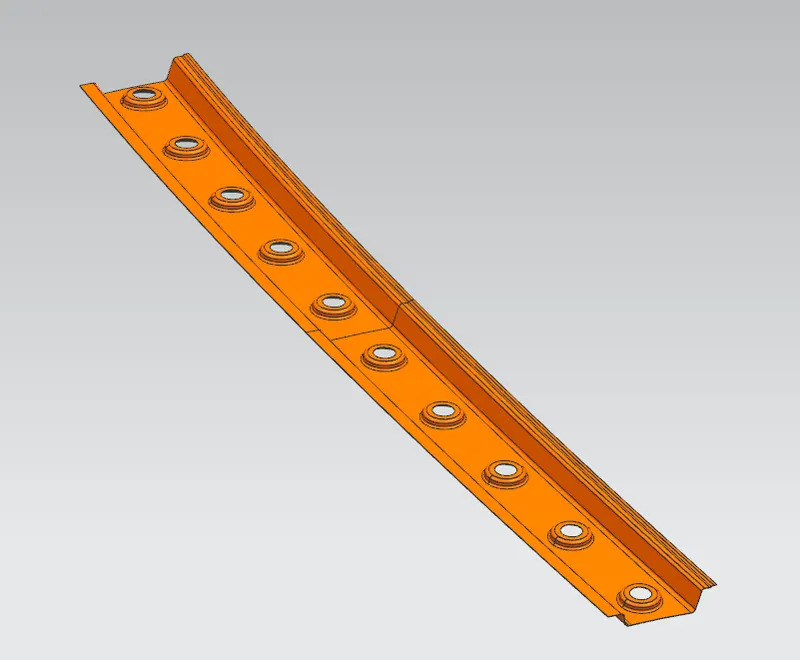
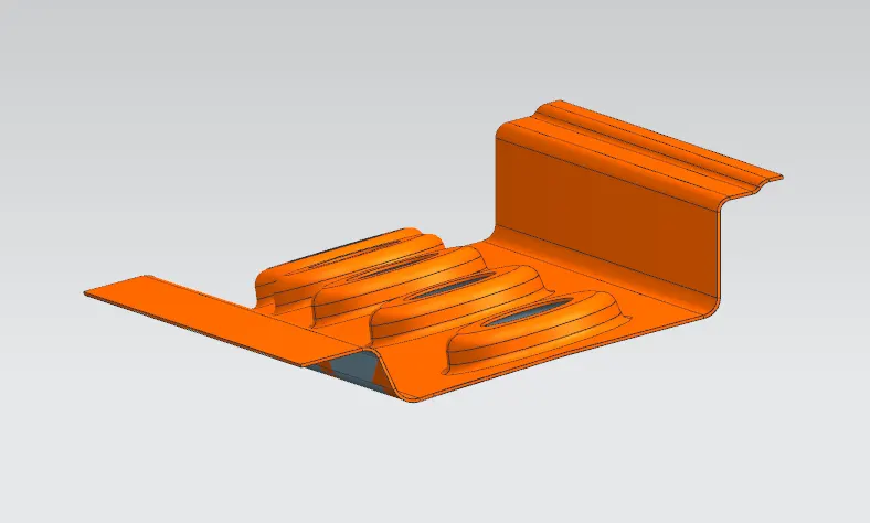
Fig:2.2 Front Roof Rail.
3. Design of Rear Roof Rail:
The rear door and the roof are connected by this roof rail. This roof rail was created with feedback from the backdoor in mind. Spot welding is used in this instance to join one end, while mastic sealants are used to join the other end.
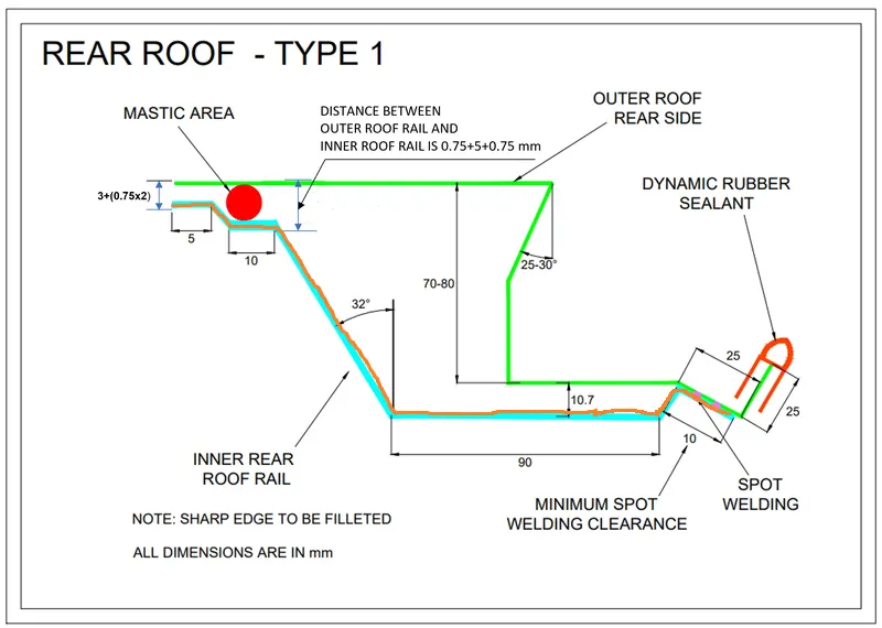
Fig:3.1 Rear Roof Rail Master Section
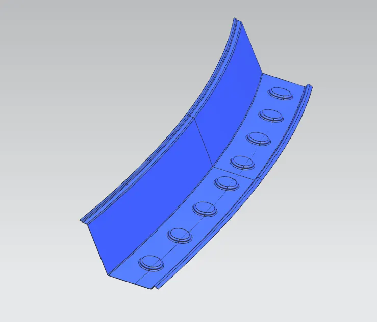
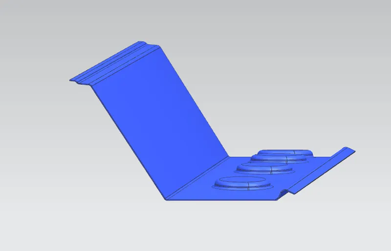
Fig:3.2 Rear Roof Rail.
4.Bow roofs:
It is an additional reinforcement provided to increase the strength of the roof. It is fixed with roof body with mastic sealants.
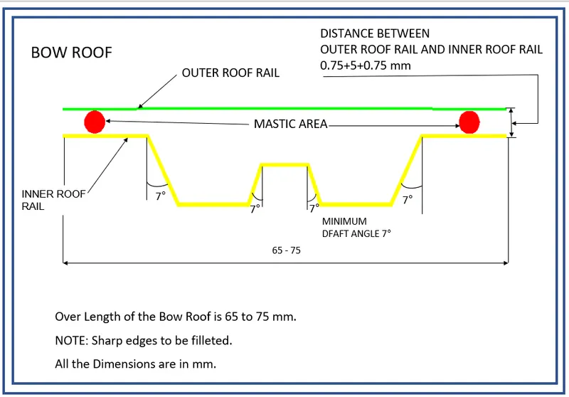
Fig:4.1 Bow Roof Master Section.
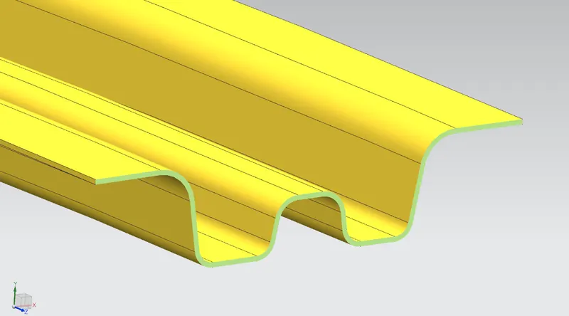

Fig:4.2 Bow Roof 1.
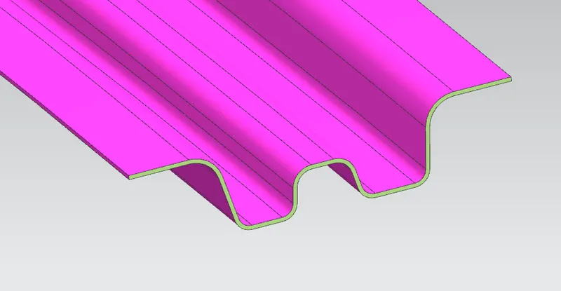
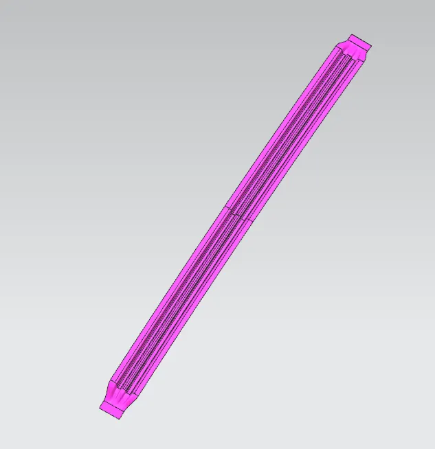
Fig:4.3 Bow Roof 2.
5.Centre roof rail
It is provided at the center of the roof to strengthen that area and it is joined to the outer panel by mastic.
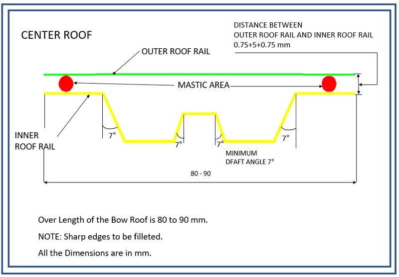
Fig:5.1 Center Roof Master Section.
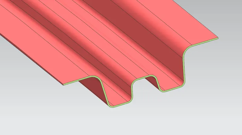
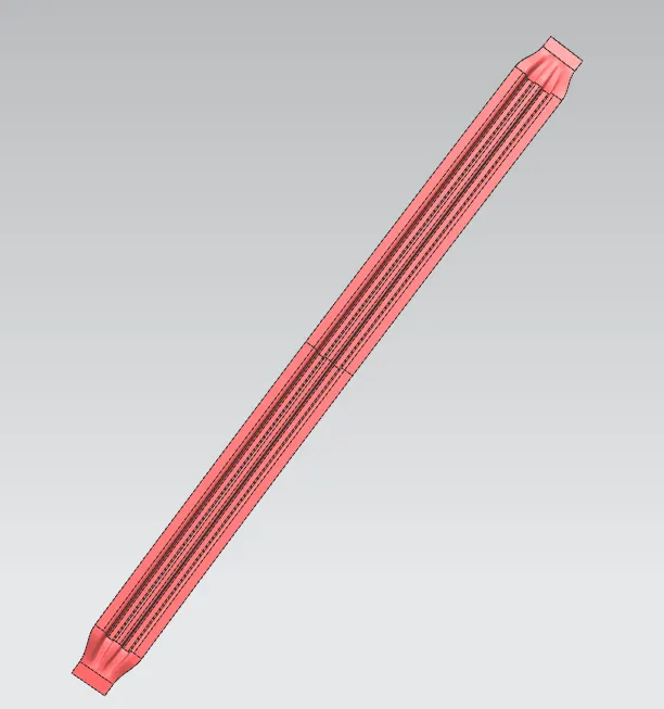
Fig:5.2 Center Roof.
6.Joining Process of the Reinforcements:
Joining of the Outer Roof Panel and the Front Roof Rail is done by Spot welding is preferred for its speed, precision, and reliability.The Front Ditch area and the front roof rail are spots welded as it is an easy and efficient process and the welding will be hidden under the windshield area so that it doesn't affect the aesthetic of the car.
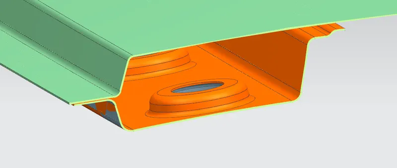
Fig:6.1Joining of Outer Roof Panel and Front Roof Rail.
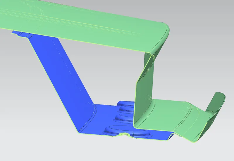
Fig:6.2 Joining of Outer Roof Panel and Rear Roof Rail.
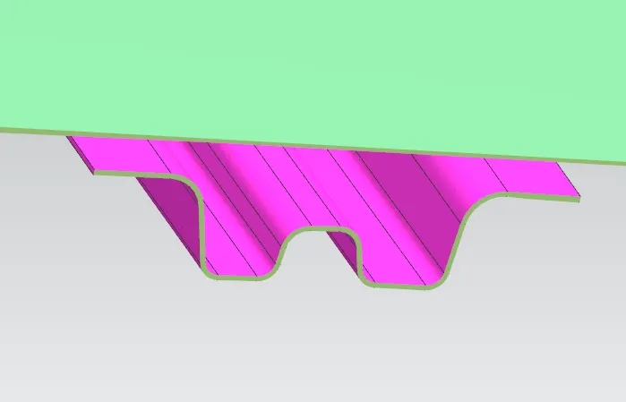
Joining of the middle part of the Outer Roof Rail, Bow Roofs, and Center Roof Rails are done by the use of Mastics Sealants. Here we cant use Spot welding because it damages the A-Class area of the Roof. So, mastic sealant is used in this area. For the application of these Mastics, there must be a gap of at least 5mm between the Roof Outer Panel, Bow Roofs, and Center Roof Rail. The ends of the Bow Roofs and Center Roof Rails are joined by spot welding to the Side Ditch area of the Outer Roof Pan
7.Curvature Study on the Roof:
- Heat Distortion calculation
- Snow Load calculation
Heat Distortion Criteria
Heat distortion criteria refers to the maximum temperature that a car roof can reach before its structural integrity is compromised. This is an important consideration for roof designers, as high temperatures can cause the roof to deform, buckle, or even fail.
This calculation is performed to check the strength of the roof at a certain load with a certain temp. This study will predict the position of bow roofs.
W = [1.73 x 10^(-3) x L] + [1.85 x 10^(-8) x (R^2)/t] + [ 1.10x10^(-3) x l] - 2.68
Where,
L = Roof Length in X-Direction[mm](Roof dimension in 0-Y)
R = Roof curvature
R = 2(Rx*Ry)/(Rx+Ry)
Rx = X curvature
Ry = Y curvature
t = Roof plate thickness [mm]
l = Bow Roof Span [mm]
Judgement Condition - OK<2.7

Fig:7.1 Heat distortion tabulation by using MS Excel
Snow Load calculation
Snow load criteria study is used to check the durability of the roof to withstand the snow fall on the roof and regain its original shape without any permanent deformation after load being removed.
Qr = [Iy x t2] / [α x s x [(Rx + Ry)/2]2 x 10-8]
Where,
α = My x Lx2 x 10-12 , My = Y(Ly-Y)
t = Roof plate thickness [mm]
Ly = Distance between the front and rear roof Rails on the Vehicle along with 0Y[mm]
Length of Roof panel with the center point between Roof rail Front /Rear as the front and rear reference point.
Lx = Distance between the Left and Right end of the roof on the Roof BOW [mm]
The width of the roof panel is exposed on the surface.
Y = Distance front Front Roof Rail to Roof BOW[mm]
s = Distance for which Roof BOW bears divided load [mm]
s = L1/2 + L2/2
Iy = Geometrical moment of inertia of Roof BOW (Y cross-section )[mm4]
Rx = Lateral direction curvature radius of roof panel Y cross-section on Roof BOW [mm]
Roof panel curvature Radius of the Length Lx in Front view
Ry = Longitudinal Direction curvature radius of the Roof panel X cross-section on Roof BOW [mm]
Roof panel X curvature radius of length s in Side view
Judgment condition Qr ≥ 3.1
250 ≤ s ≤ 380
Moment of Inertia for the Roof Rails:
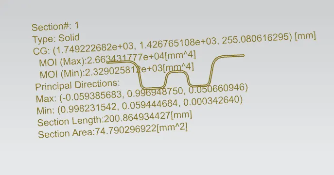
Fig:7.2 Moment Of Inertia of Bow Roof 1.
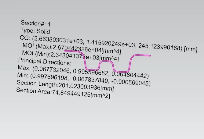
Fig:7.3 Moment Of Inertia of Bow Roof 2.
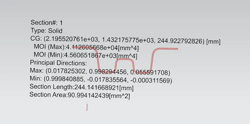
Fig:7.4 Moment Of Inertia of Centre Roof Rail.

Fig:7.5 Heat distortion tabulation by using MS Excel
From the calculations we found Bow roof 2 has NG, So we have to ask the styling team to modify the surface with curvature in the y-axis (Ry).
8.Draft Analysis:
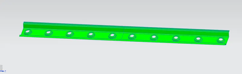
Fig:8.1 Draft Analysis on Front Roof Rail.
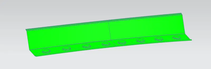
Fig:8.2 Draft Analysis on Rear Roof Rail.
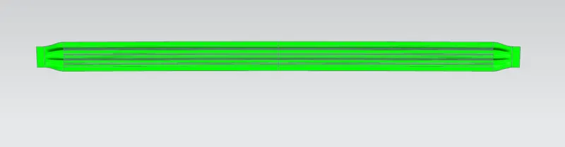
Fig:8.3 Draft Analysis on Bow Roof 1.
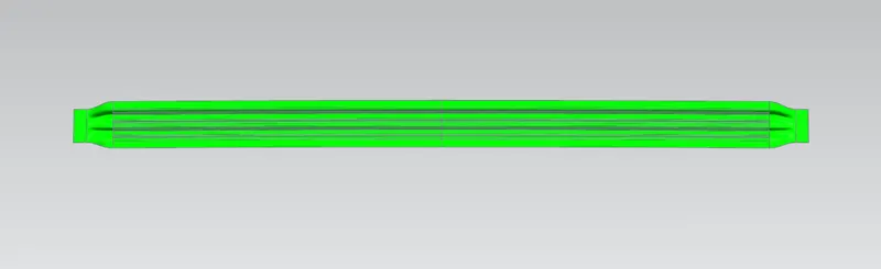
Fig:8.4 Draft Analysis on Bow Roof 2.
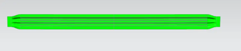
Fig:8.5 Draft Analysis on Center Roof Rail.
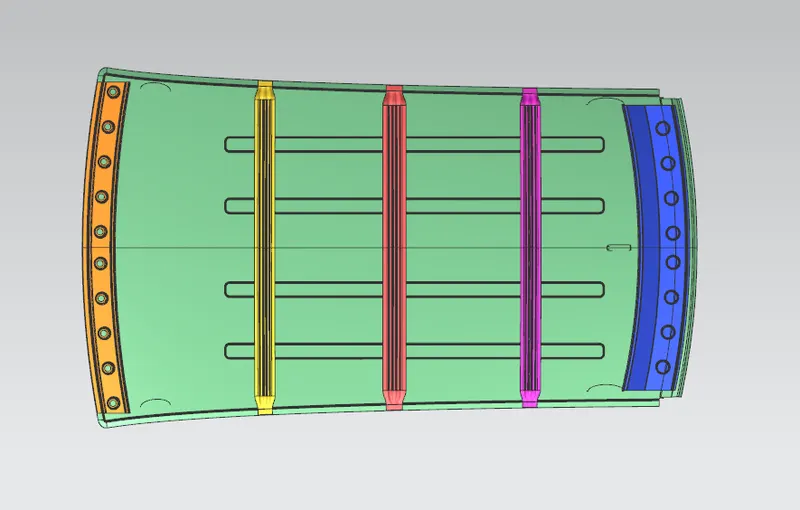
Final Roof:
Conclusion:
Thus the required reinforcements and Ditch Area for the Roof were designed and developed from the given styling. The curvature study was done after performing calculations for the Heat Distortion and Snow load conditions with the position criterion met for all reinforcements.
Further, the Section Inertia study was conducted and a Draft Analysis was done for each reinforcement successfully.