Roof Design
Objective :
Design a roof with its components by following the master section of the front roof rail with all the design parameters and doing the curvature research and calculating the heat distortion study and snow load criterion, section modulus, and draught analysis of each reinforcement.
Introduction :
An automobile roof or car top is the portion of a vehicle that is located above the passenger compartment. It covers and protects the vehicle occupants/passengers from the sun, wind, rain, and other external factors. It has provided some reinforcement to help strengthen this section. It is curved because a flat roof is more likely to flex if a weight is applied.
Roof Reinforcement :
- Front Roof Rail
- Bow Roof Rail
- Center Roof Rail
- Rear roof Rail
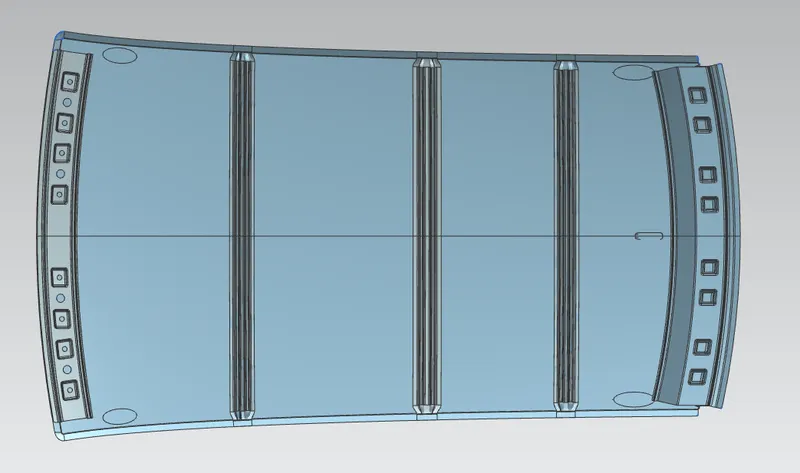
Front Roof Rail: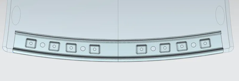
The front roof rail is given at the front end of the roof to offer strength to that section of the roof, however while constructing this component, we must keep vision and headroom clearance in mind. Embosses are used to reinforce the front roof rail.
Bow Roof Rail:
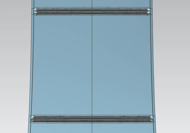
It is provided to strengthen the roof in certain areas, and it may be made in any number depending on the length of the roof. To connect the bow roofs to the outer panel, mastic points are supplied.
Center Roof Rail:
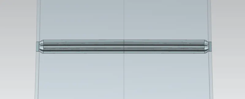
It is placed in the middle of the roof to strengthen that region, and it is mastically attached to the outside panel.
Rear roof Rail:
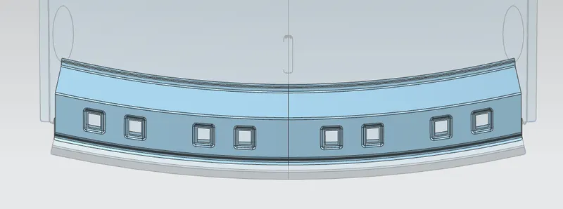
It is located at the back of the roof and is attached to the outer roof by spot welding. While designing this, we should keep rear headroom and visibility criteria in mind. Embosses are used to reinforce the rear roof rail.
Mastic points:
Mastics are placed between the outer panel of the roof and the reinforcements for connecting. Wherever the mastic is administered, the strength improves noticeably. Spot welding is also used to connect the reinforcements to the outer panel.
Roof design consideration :
- Visibility criteria
- Head clearance
- Curvature study
- Heat distortion
- Snow load criteria
- Draft analysis
Heat Distortion Criteria:
This formula is used to determine the strength of the roof at a given load and temperature. This research will forecast the location of bow roofs.
W = [1.73 x 10^(-3) x L] + [1.85 x 10^(-8) x (R^2)/t] + [ 1.10x10^(-3) x l] - 2.68
Where,
L = Roof Length in X-Direction[mm](Roof dimension in 0-Y)
R = Roof curvature
R = 2(Rx*Ry)/(Rx+Ry)
Rx = X curvature
Ry = Y curvature
t = Roof plate thickness [mm]
l = Bow Roof Span [mm]
Judgement Condition - OK<2.7
Calculation Column:
| W = [1.73 x 10^(-3) x L] + [1.85 x 10^(-8) x (R^2)/t] + [ 1.10x10^(-3) x l] - 2.68 mm | |||||||||||
| R =2(Rx*Ry)/(Rx+Ry) | |||||||||||
| Sl.no | Roof Rail | L (mm) | Rx (mm) | Ry (mm) | Rx*Ry | Rx+Ry | R (mm) | t (mm) | l (mm) | W | Result |
| 1 | FR - Bow1 | 2027.9 | 2839.78 | 5708.92 | 16212076.84 | 8548.7 | 3792.87537 | 0.75 | 533.3 | 1.769482 | Pass |
| 2 | Bow1 - CR | 2027.9 | 7166.08 | 4731.57 | 33906809.15 | 11897.65 | 5699.748966 | 0.75 | 557.7 | 2.242819 | Pass |
| 3 | CR - Bow2 | 2027.9 | 11411.04 | 3817.93 | 43566551.95 | 15228.97 | 5721.536249 | 0.75 | 419.7 | 2.097157 | Pass |
| 4 | Bow2 -RR | 2027.9 | 14646.37 | 3271.39 | 47913988.35 | 17917.76 | 5348.21187 | 0.75 | 364.2 | 1.93417 | Pass |
According to the above table, all values of w<2.7 indicate that the bow row alignment is in satisfactory condition and acceptable.
Snow load criteria:
This test is performed to determine how the roof behaves when there is snow on it. The dent is usually caused by the weight of the snow. However, the roof should be built so that after the snow is removed, the roof returns to its original position. This is the fundamental requirement for snow load criteria.
Qr = [Iy x t2] / [α x s x [(Rx + Ry)/2]2 x 10-8]
Where,
α = My x Lx2 x 10-12 , My = Y(Ly-Y)
t = Roof plate thickness [mm]
Ly = Distance between the front and rear roof Rails on the Vehicle along with 0Y[mm]
Length of Roof panel with the center point between Roof rail Front /Rear as the front and rear reference point.
Lx = Distance between the Left and Right end of the roof on the Roof BOW [mm]
The width of the roof panel is exposed on the surface.
Y = Distance front Front Roof Rail to Roof BOW[mm]
s = Distance for which Roof BOW bears divided load [mm]
s = L1/2 + L2/2
Iy = Geometrical moment of inertia of Roof BOW (Y cross-section )[mm4]
Rx = Lateral direction curvature radius of roof panel Y cross-section on Roof BOW [mm]
Roof panel curvature Radius of the Length Lx in Front view
Ry = Longitudinal Direction curvature radius of the Roof panel X cross-section on Roof BOW [mm]
Roof panel X curvature radius of length s in Side view
Judgment condition Qr ≥ 3.1
Calculation Column:
| Qr = [Iy x t2] / [α x s x [(Rx + Ry)/2]^2 x 10-8] | |||||||||||||||
| α = My x Lx2 x 10^-12 | My = Y(Ly-Y) | s = L1/2 + L2/2 | |||||||||||||
| Sl.no | Roof Rail | Iy | α | Lx | Ly | Y | My | L1 | L2 | S | Rx | Ry | t | Qr | Result |
| 1 | FR - Bow1 | 2506 | 0.94937983 | 1103.8 | 1954.9 | 557.7 | 779218.44 | 547 | 558.5 | 552.75 | 4330.46 | 12112.1 | 0.75 | 3.974276 | Pass |
| 2 | Bow1 - CR | 2780 | 1.065236699 | 1066.7 | 1954.9 | 1116.1 | 936184.68 | 558.5 | 420.1 | 489.3 | 3839.88 | 7131.38 | 0.75 | 9.97E-09 | Pass |
| 3 | CR - Bow2 | 2526 | 0.710904396 | 1051.4 | 1954.9 | 1536.3 | 643095.18 | 420.1 | 383.1 | 401.6 | 4358.51 | 2826.02 | 0.75 | 3.86E-08 | Pass |
As seen above the roof structure passes to the snow load condition as Qr values are above 3.1.
Section moment of inertia:
The section moment of inertia is used to predict how much a component will bend and deflect. A larger moment of inertia is preferred since it reduces deflection for a given force. The addition of flanges and embosses, as well as the thickness of the component, enhance the section inertia of the part. The master sections of the roof and roof rails, as well as their section analysis, are provided here.
- Front Roof Rail:
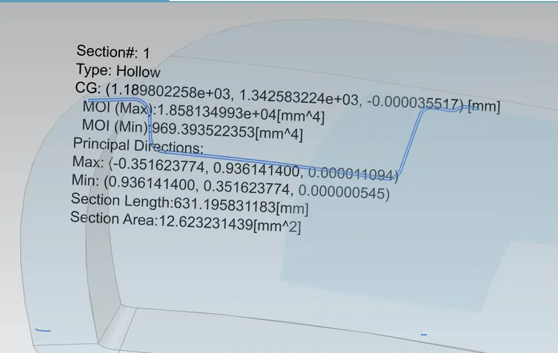
Moment of inertia maximum,( MAX) I max = 1.8581e+04 mm^4
Moment of inertia maximum ,( MIN) I min = 969.393 mm^4
- Bow 1 Roof Rail:
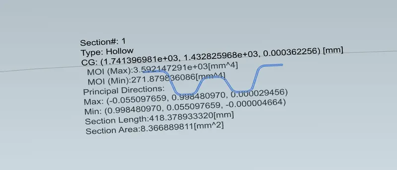
Moment of inertia maximum,( MAX) I max = 3.5921e+03 mm^4
Moment of inertia maximum ,( MIN) I min = 271.879 mm^4
- Center Roof rail:
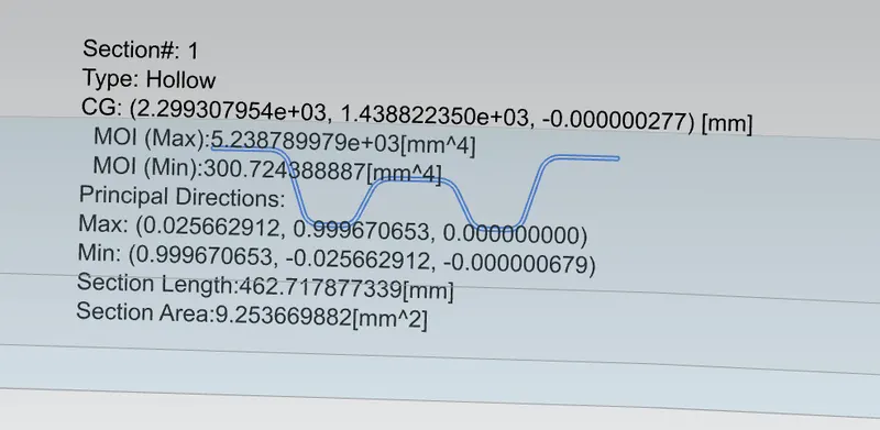
Moment of inertia maximum,( MAX) I max = 5.238e+03 mm^4
Moment of inertia maximum ,( MIN) I min = 300.724 mm^4
- Bow 2 roof rail:
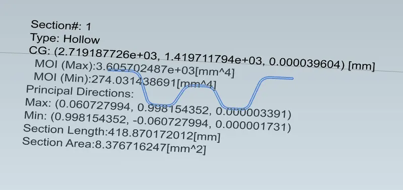
Moment of inertia maximum,( MAX) I max = 3.605e+03 mm^4
Moment of inertia maximum ,( MIN) I min = 274.031 mm^4
- Rear Roof rail :
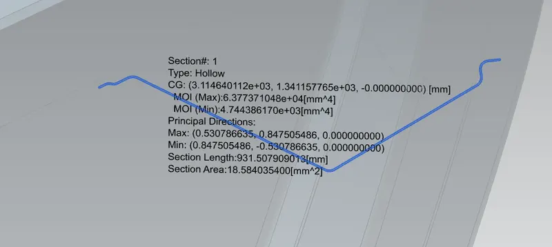
Moment of inertia maximum,( MAX) I max = 6.377e+04 mm^4
Moment of inertia maximum ,( MIN) I min = 4.744e+03 mm^4
Draft Analysis:
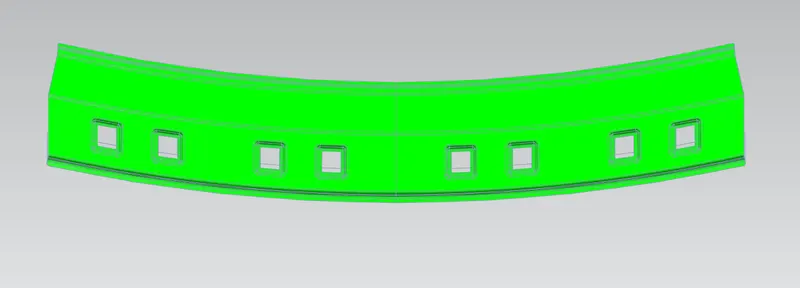
The Draft Analysis command determines if the portion you drafted is easily removable. This method of analysis is based on colour ranges that define zones on the analysed element where the deviation from the draft direction at any point corresponds to specified values. For analysis, a minimum draught angle of 7 degree is taken into account. Green colour denotes that all faces along the tooling direction have a positive draught angle greater than 7 degree and have passed analysis.
- Draft Analysis for Front Roof Rail
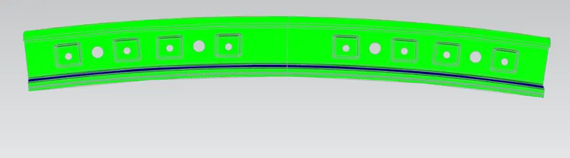
- Draft Analysis for Bow Roof Rail 1
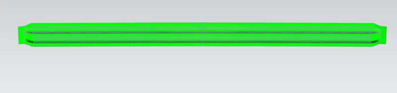
- Draft Analysis for Center Roof Rail
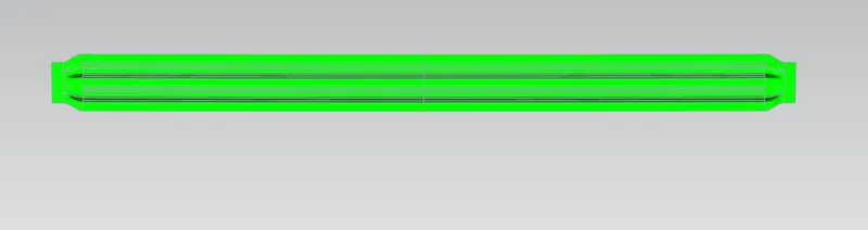
- Draft Analysis for Bow Roof Rail 2
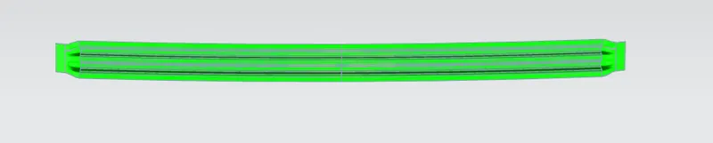
- Draft Analysis for Rear roof Rail
Conclusion:
As a result, the roof, front roof rail, bow roof rails, centre roof rail, and rear roof rail are built in accordance with the master sections, and the moment of inertia and draft analysis are performed to ensure manufacturing feasibility.