Roof Design
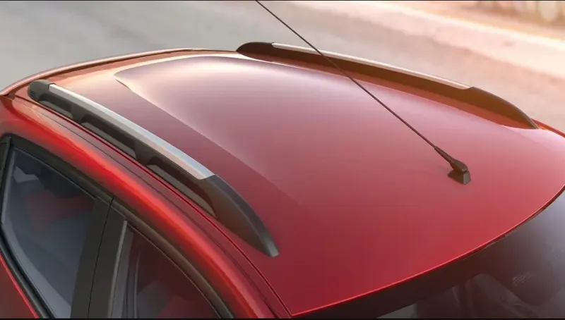
ROOF DESIGN
Objective:
- This project's goal is to create a car roof with the necessary flanges and supports for the specified style surface, including a ditch region, front roof rail, bow roofs, center roof rail, and rear roof rail.
- To ascertain whether the bow roofs are in the proper positions, evaluate the roof's curve and calculate the snow load and heat distortion criterion.
- Calculate the section modulus and moment of inertia for Bow roofs' central, front, and rear roof rails for each reinforcement, and conduct the draught analysis.
Introduction:
- Any product's design begins with a requirement. Based on the specifications, the design engineer creates a drawing of the product.
- Then, the 2D sketch with the correct dimensions is turned into a 3D model using sophisticated CAD software. Every product should be able to be manufactured, which is another crucial aspect of design.
- Therefore, the design engineer's job is to create products that are simple to produce and less expensive to produce.
- When creating any product, the Design for Manufacturing (DFM) and Design for Assembly (DFA) play an important part.
- The design is developed until it meets the needs of the client, at which point it is finished.
Types Of Roof:
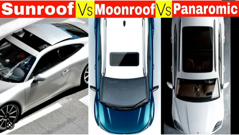
- Moonroof and Sunroof are the two Types of Roof Panels and their Differences.
- They really aren't that different from one another, despite having names that range from day to night.
- The Panoramic sun/ moonroof is a type of moonroof that has either several panels that are either moveable or fixed in place or one long panel that covers the front and rear seats. This allows both the front and rear passengers to have access to the sun/moonroof.
- The first automobiles had absolutely no roofs when they were first created.
Various Forms Of Reinforcement In Roof Top:
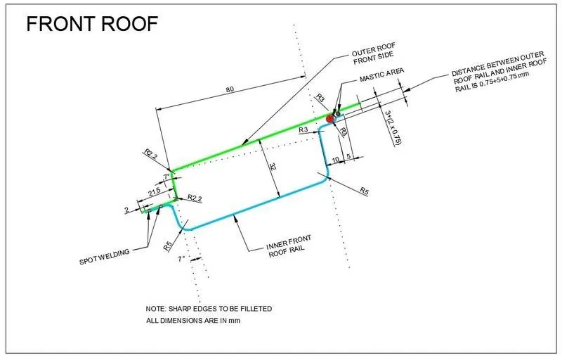
- Front Roof Rail
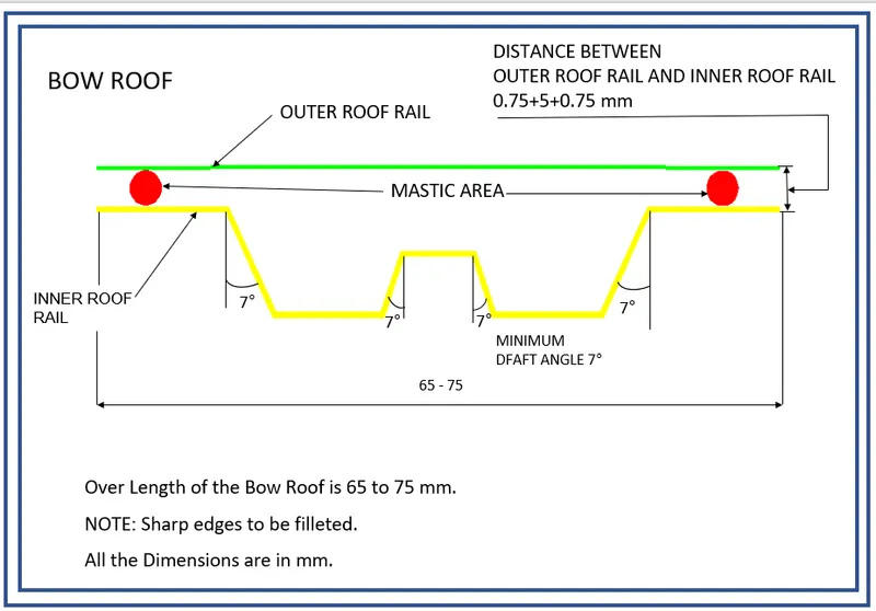
- Bow Roof Rail
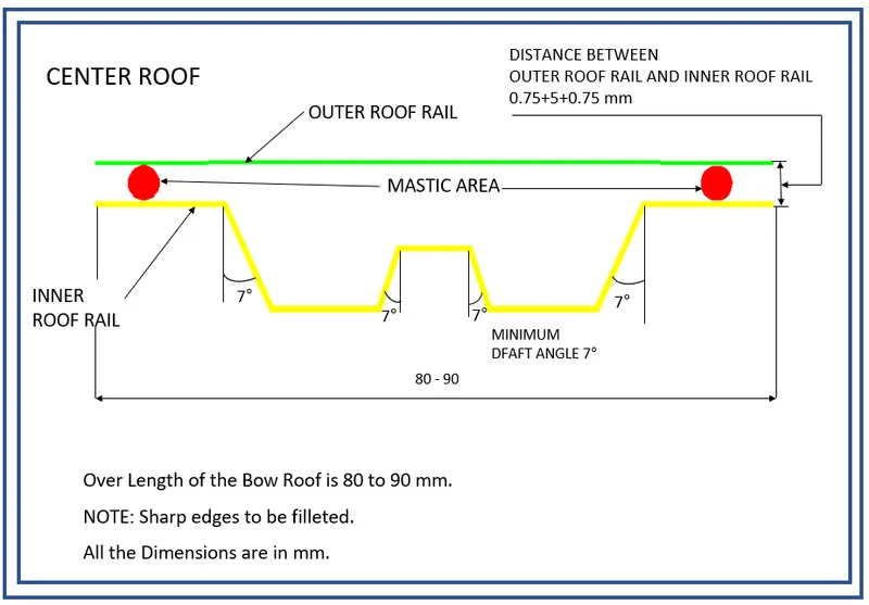
- Center Roof Rail
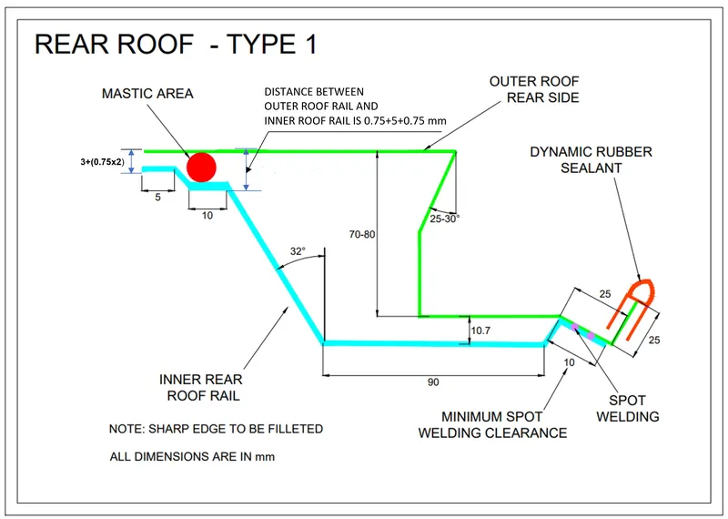
- Rear Roof Rail
Front Roof Rail:
- The front roof rail is nothing that connects the body side outer and inner panels as well as the windshield glass. Here, the front roof rail is created using the provided master section.
Bow Roof Rail:
- The purpose of bow roof rails is to increase the roof structure's torsional rigidity and load-carrying capacity.
- The amount of bow roofs that are present depends on the size of the roof as a whole, this project is adding two bow roofs.
Center Roof Rail:
- The flat portion of the roof is more prone to failure due to the action of stress, hence a central roof rail aids in properly supporting it.
- The B-pillar support structure is connected to the central roof rail, which is typically located at the center of the roof.
- During the roll-over test, this central roof rail contributes to the strength of the roof.
- The main roof rail is 1.25 millimeters thick.
Rear Roof Rail:
- The rear roof rail is the piece that connects the back door to the exterior body side.
Roof Design Consideration:
- Visibility standards.
- Maximum headroom.
- Bow roof placement.
- Criteria for Heat Distortion and Snow Load Prediction.
- Draft evaluation.
The roof crush test:
- Crash Test for Roof illustration is a government initiative tasked with assessing the performance of new automotive designs in relation to numerous safety hazards.
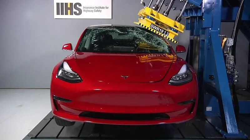
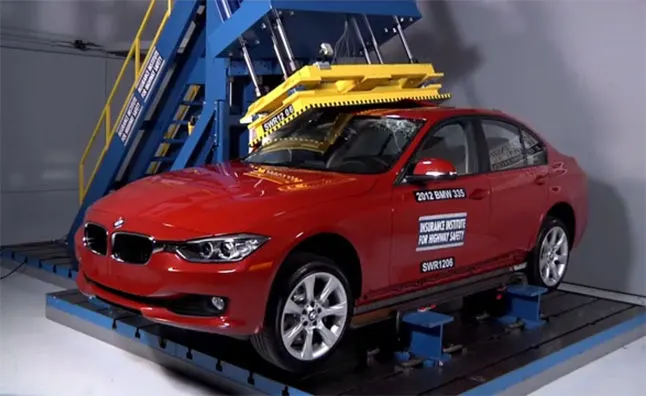
- specifies evaluating a car's roof on one side excludes the headroom requirement and outlines testing to a specified displacement rather than a specified force level.
- Outlines to adjust the vehicle's pitch angle during testing based on the on-road pitch angle that was measured.
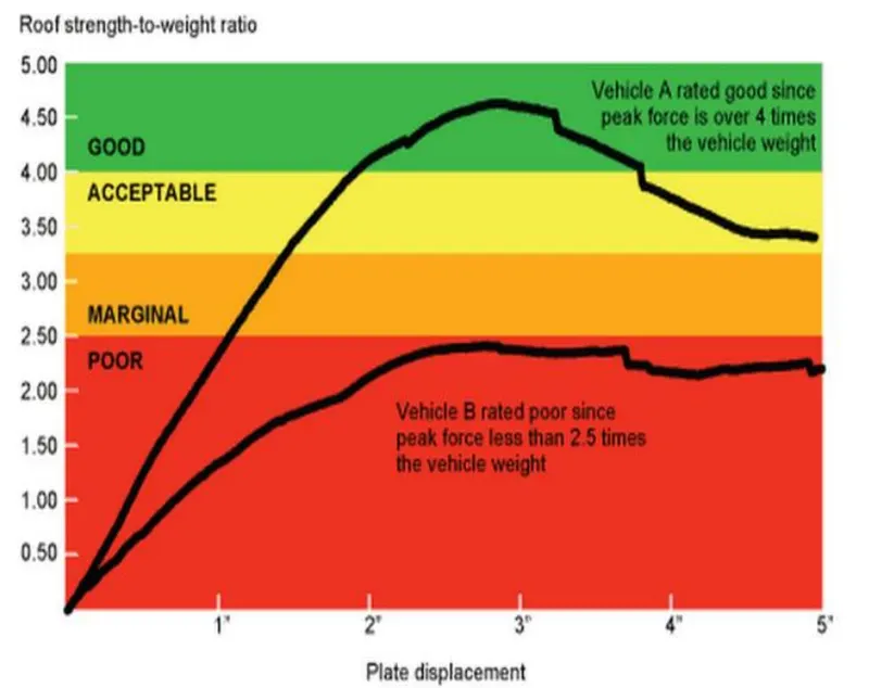
- Peak strength-to-weight ratio (SWR) measurements taken within 127 mm of plate displacement are used to get an overall rating.
Assessment Of Roof:
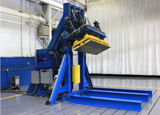
- A quasi-static test equipment made by MGA Research Corporation is used to evaluate roof strength.
- The system comprises an upright assembly with a loading head connected that can be fixed at different heights from the ground as well as at pitch angles ranging from 5 to +5 degrees to accommodate testing on the driver or passenger side.
- The roll angle is set at 25 degrees all the time.
- The platen travels along two linear guides under the control of four hydraulic actuators.
- The complete system is fixed to a T-slot bed plate that is fastened to the test facility's floor.
- On the bed plate, two HR A-36 — W10x88 I-beams are placed perpendicular to the platen’s longitudinal axis.
- The vehicle is positioned on these beams with a rocker panel support system connected.
- The car is configured within 10 mm of the initial point of roof contact is the platen's longitudinal centerline.
- The vehicle's yaw angle is 0 0.5 degrees with respect to the longitudinal axis of the platen.
- The windscreen trim, if it overlaps the roof, is 254 10 mm forward of the furthest forward point of the roof at halfway along the longitudinal midline of the vehicle.
- The vehicle's pitch angle equals the on-road angle and accounts for any discrepancy between the four linear variable displacement transducers (LVDTs) (MTS Temposonics model GH) built within the hydraulic actuators used to measure displacement.
- The placement of the load cells and LVDTs on the loading plate is depicted in Data on force and displacement are gathered and reported at 100 Hz using a National Instruments USB-6210 data gathering system. These statistics are based on 2,000 Hz sampling, with 20-point averages used to provide output data at 100 Hz.
- To confirm that the platen's roll angle and pitch angle (relative to the vehicle's on-road pitch) were kept at 25 0.5 degrees and 5 0.5 degrees, respectively, the displacement-time records from the LVDTs are compared.
- Each test vehicle's pre-crash and post-crash conditions are recorded.
Strength-To-Weight Ratio (SWR) Rating Calculation For Roof:
- Prior to each test, 5 seconds of force and displacement data are gathered while the test system holds the loading platen at initial roof contact.
- In order to create a measurement offset that may be subtracted from the data captured during the crushing of the roof, the data recorded during the first to fourth seconds of this hold time are averaged for each channel.
- The force-displacement curve is produced using the average displacement from the four LVDTs and the sum of the output from the five load cells after the offset for each channel has been removed.
- The SWR is calculated by dividing the highest force prior to 127 mm of platen displacement by the measured curb weight.
- Prior to the performance, the force and curb weight are both rounded to the closest pound.
Design Requirements For The Roof Design Components:
- Data from the master section for the reinforcement, Front and Rear Roof Rails, and 2-Bow Roof Rails and Given Reinforcements.
- Master portions should only be used as a guide.
Formula Given For Heat-Distortion & Snow Load Prediction:
Heat-Distortion Formula:
W = [1.73 x 10^(-3) x L] + [1.85 x 10^(-8) x (R^2)/t] + [ 1.10x10^(-3) x l] - 2.68
Where,
L = Roof Length in X-Direction[mm](Roof dimension in 0-Y)
R = Roof curvature
R = 2(Rx*Ry)/(Rx+Ry)
Rx = X curvature
Ry = Y curvature
t = Roof plate thickness [mm]
l = Bow Roof Span [mm]
Judgment Condition:
- OK< 2.7
Snow Load Prediction Formula:
Qr = [Iy x t2] / [α x s x [(Rx + Ry)/2]2 x 10-8]
Where,
α = My x Lx2 x 10-12 , My = Y(Ly-Y)
t = Roof plate thickness [mm]
Ly = Distance between the front and rear roof Rails on the Vehicle along with 0Y[mm]
Length of Roof panel with the center point between Roof rail Front /Rear as the front and rear reference point.
Lx = Distance between the Left and Right end of the roof on the Roof BOW [mm]
The width of the roof panel is exposed on the surface.
Y = Distance front Front Roof Rail to Roof BOW[mm]
s = Distance for which Roof BOW bears divided load [mm]
s = L1/2 + L2/2
Iy = Geometrical moment of inertia of Roof BOW (Y cross-section )[mm4]
Rx = Lateral direction curvature radius of roof panel Y cross-section on Roof BOW [mm]
Roof panel curvature Radius of the Length Lx in Front view
Ry = Longitudinal Direction curvature radius of the Roof panel X cross-section on Roof BOW [mm]
Note:
Roof panel X curvature radius of length s in Side view
Judgment condition:
- Qr ≥ 3.1
Procedure To Create a Roof Design:
DESIGN CONSIDERATION-
- Visibility criteria
- Head clearance
- Curvature study
- Hear distortion and snow load criteria
- Draft analysis.
Components of roof-
1.Front Roof Rail-
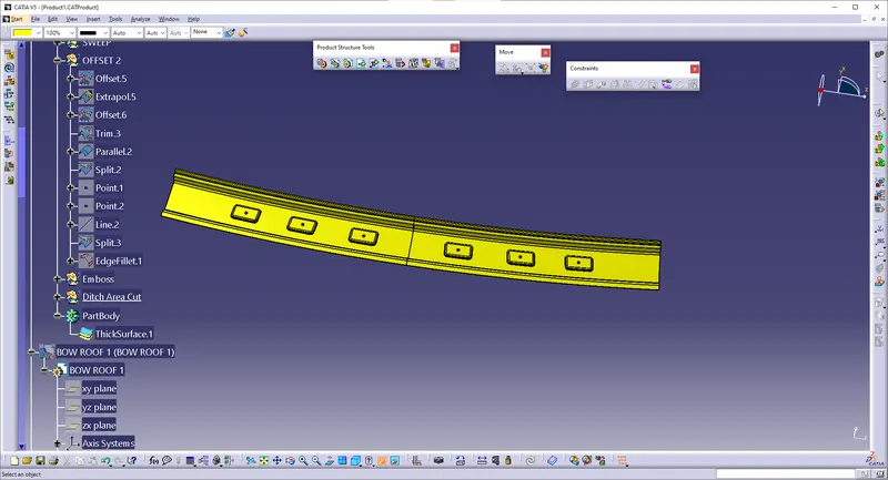
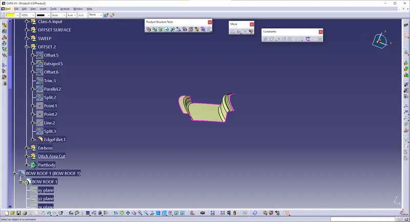
The front roof rail is located on the front of the roof where the wind shield joins with the roof. The visibility criteria and the head room clearance of the passenger are taken into consideration for the bottom flange. One end of the rail is joined using spot welding while the other end is joined with the roof using mastic sealants for increased strength.
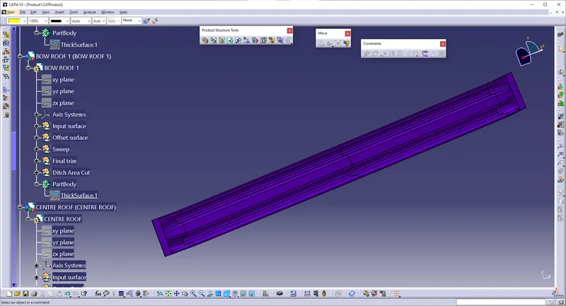
2.Bow roof 1-
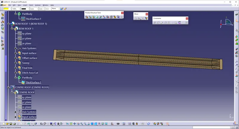
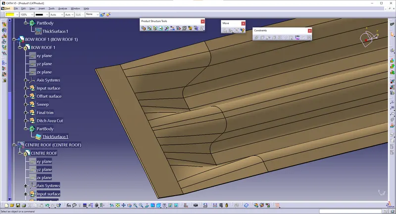
Bow roof is an additional siffening member for the roof to increase the strength and so that it can satisfy the norms. Both the ends are joined together using mastic sealants to increase strenght and also since this would not affect the styling of the roof.
3.Centre Roof Rail-
Centre Roof rail or the reinforcement centre is located at the centre of the roof . The cross section of this is more since it needs to provide more strength to the roof. Here both are ends are joined together using mastic sealants.
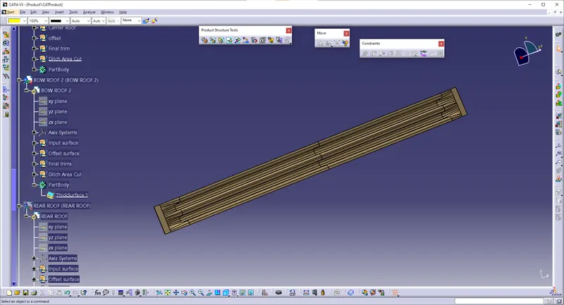
4.Bow roof 2-
This bow roof also have the same purpose as that of the first one. This one is located between the centre bow roof and rear roof rail.
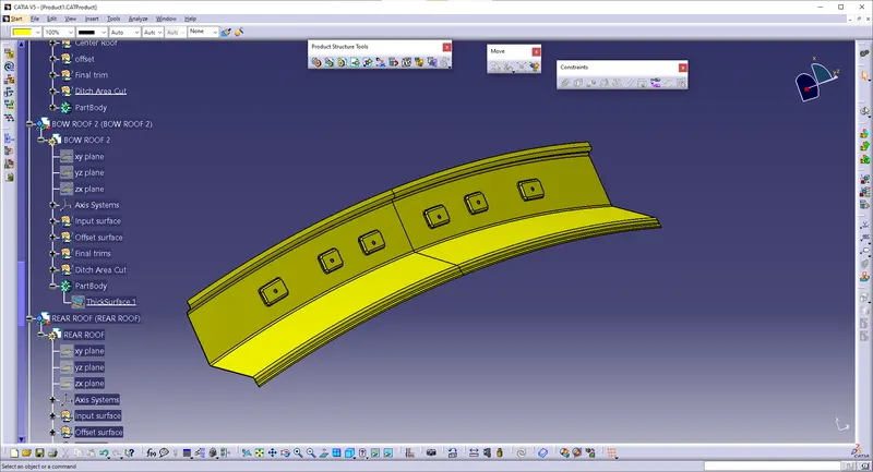
5.Rear Roof Rail-
- This roof rail joins with the back door and the roof. Inputs from the backdoor are taken into consideration for designing this roof rail.
- Here one end is joined using spot welding while the other end is joined using mastic sealants.
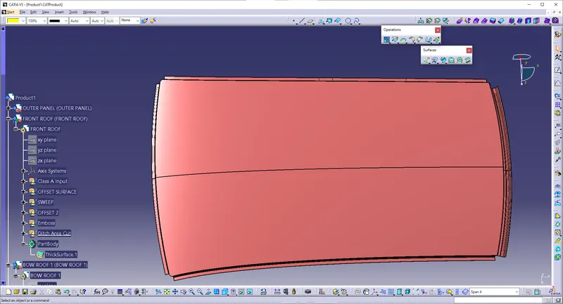
6.OUTER PANEL:
Calculation-
We then also make the ditch area around the roof.
Ditch area the extended portion of the main roof concealed by other BIW panels.
Bow–Roof Prediction Formula-
W = [1.73 x 10^(-3) x L] + [1.85 x 10^(-8) x (R^2)/t] + [ 1.10x10^(-3) x l] - 2.68
Where,
L = Roof Length in X-Direction[mm](Roof dimension in 0-Y)
R = Roof curvature
R = 2(Rx*Ry)/(Rx+Ry)
Rx = X curvature
Ry = Y curvature
t = Roof plate thickness [mm]
l = Bow Roof Span [mm]
Judgment Condition-
OK< 2.7
| Data | X Curvature (Rx) | Y Curvature (Ry) | 2(Rx * Ry) | Rx+Ry | Roof Curvature | Length I | Thickness | Total Span | W |
| Span1_Front_BR1 | 2426.811 | 5741.227 | 27865745.67 | 8168.038 | 3411.55926 | 336.272 | 0.75 | 2039.049 | 1.504542806 |
| Span2_Center_BR1 | 6205.864 | 4970.208 | 61688869.8 | 11176.072 | 5519.727307 | 427.897 | 0.75 | 2039.049 | 2.069770412 |
| Span3_Center_BR | 10550.492 | 3983.494 | 84055643.16 | 14533.986 | 5783.38545 | 433.287 | 0.75 | 2039.049 | 2.149209969 |
| Span4_Rear_BR2 | 14742.078 | 3256.937 | 96028038.59 | 17999.015 | 5335.182986 | 292.726 | 0.75 | 2039.049 | 1.871669748 |
Snow Load Prediction Formula-
Qr = [Iy x t2] / [α x s x [(Rx + Ry)/2]2 x 10-8]
Note: The Qr value given over here is correct. There was a typo error in the formula given in the video.
Where,
α = My x Lx2 x 10-12 , My = Y(Ly-Y)
t = Roof plate thickness [mm]
Ly = Distance between the front and rear roof Rails on the Vehicle along with 0Y[mm]
Length of Roof panel with the center point between Roof rail Front /Rear as the front and rear reference point.
Lx = Distance between the Left and Right end of the roof on the Roof BOW [mm]
The width of the roof panel is exposed on the surface.
Y = Distance front Front Roof Rail to Roof BOW[mm]
s = Distance for which Roof BOW bears divided load [mm]
s = L1/2 + L2/2
Iy = Geometrical moment of inertia of Roof BOW (Y cross-section )[mm4]
Rx = Lateral direction curvature radius of roof panel Y cross-section on Roof BOW [mm]
Roof panel curvature Radius of the Length Lx in Front view
Ry = Longitudinal Direction curvature radius of the Roof panel X cross-section on Roof BOW [mm]
Roof panel X curvature radius of length s in Side view
Judgment condition
Qr ≥ 3.1
| Data | Iy | t^2 | Y | Ly | My | Lx^2 | α = My x Lx^2 x 10^-12 | L1 | L2 | s = (L1+ L2)/2 | Rx | Ry | (Rx+Ry)/2 | [(Rx+Ry)/2]^2 | (Iy*t^2) | [α x s x [(Rx + Ry)/2]2 x 10-8] | Qr |
| Snow Load Prediction 1 | 7701 | 1.5 | 466.728 | 2035.741 | 732302.2995 | 1048545.28 | 0.7678521198 | 382.538 | 432.502 | 407.52 | 10535.974 | 10623.224 | 10579.599 | 111927915 | 11551.5 | 350.2393425 | 32.98173163 |
| Snow Load Prediction 2 | 7091 | 1.5 | 508.418 | 2035.741 | 776518.505 | 970492.9385 | 0.7536057257 | 432.502 | 435.468 | 433.985 | 10464.863 | 10824.883 | 10644.873 | 113313321.2 | 10636.5 | 370.5952746 | 28.70112149 |
| Snow Load Prediction 3 | 7732 | 1.5 | 511.267 | 2035.741 | 779413.2486 | 930694.3256 | 0.7253954877 | 435.468 | 337.051 | 386.2595 | 10190.836 | 10275.495 | 10233.1655 | 104717676.2 | 11598 | 293.4093976 | 39.52838626 |
DRAFT ANALYSIS:
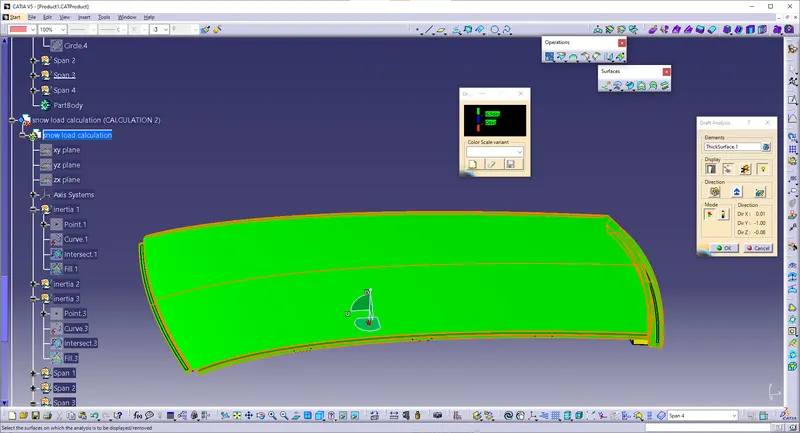
CONCLUTION-
- SINCE ITCOMES UNDER JUDGEMENT CONDITION IS SAFE.
- DESIGN IS SAFE
- TO SUPPORT THE 1 CENTER ROOF, 2 BOW ROOF IS ENOUGH.
- THE CONDITION Qr>3.1 IS NOT SATISFIED.
- THE ROOF MAY FACE BEND DUE TO SNOW LOADING, SINCE ITS NOT SATISFIED.
- OR IN ORDER TO MAKE THE ROOF STRONG WE CAN ADD EMBOSS TO THE OUTER ROOF.
- INCRESING THE EMBOSS DISTANCE, DUE TO CHANGEING THE SHAPE OF ROOF THE INERTIA VALUE WILL BE GREATER AND INCREASING THE THICKNESS OF THE BOW ROOF - THESE ARE THE WAYS TO SATISFY THE CONDITIONS.
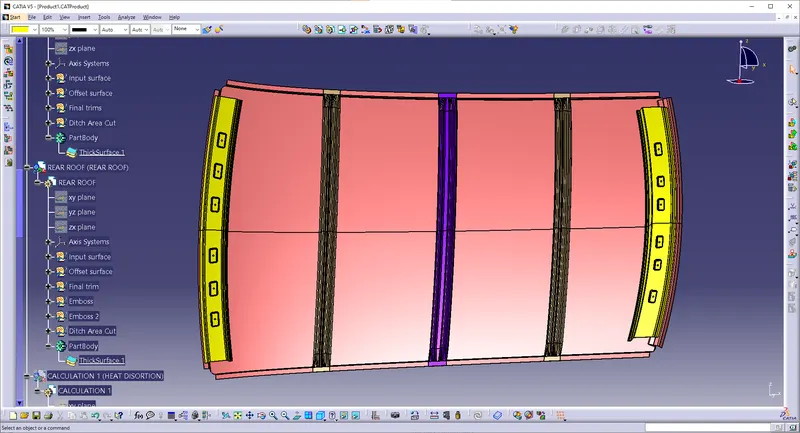
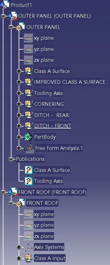
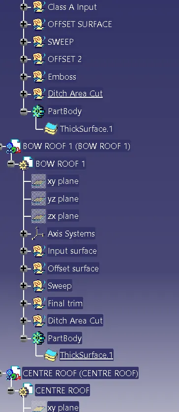
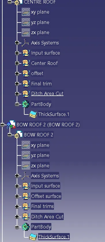
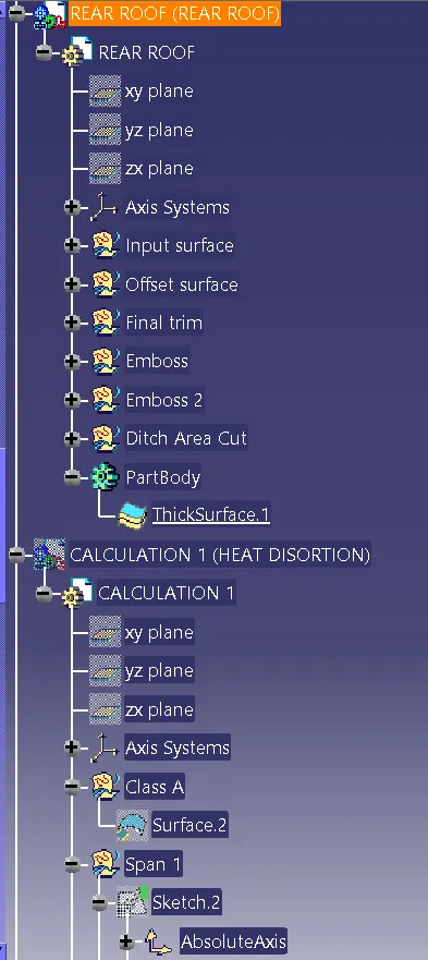
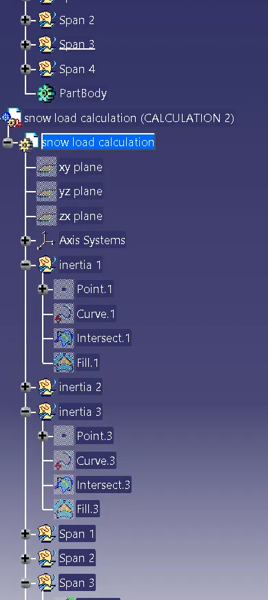
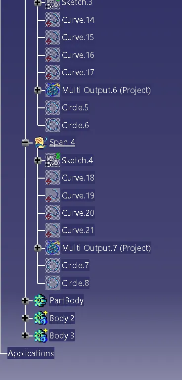
TREE STRUCTURE: