Week 8 - Challenge 3 - Coin Holder Design
DESIGN AND DRAFT ANALYSIS OF COIN HOLDER :
OBJECTIVE:
The objective of the project is to design the COIN HOLDER and to do a draft analysis for it by creating the required tooling direction with the help of Bisecting method.
INTRODUCTION:
To create the COIN HOLDER component through the given Class-A surface. To begin with, the tooling axis for the given Class-A Surface should be created meeting the requirements of the draft angle and at the end perform the Draft analysis on the model.
Take the Thickness of the component to be 2.5 mm.
DESIGN CONSIDERATION:
- Class – A surface should be aesthetically smooth and good.
- Class – B surface should have all the supporting features like ribs.
- Parting Line should coincide with the B surface since flashing couldn’t affect the aesthetic of Class – A.
- Class – C surface should also pass the draft analysis.
PROCEDURE FOR CREATING THE COIN HOLDER :
- First, the given styling surface is checked for any irregularities and if found any then it is corrected by using Trim, Extrapolate, Split and Join commands.
- The below image shows that the Class – A surface is clean and no irregularities present, so let's move on to the next step.
CREATION OF TOOLING DIRECTION
- Considering the Ejection from the cavity of the mould after manufacturing the COIN HOLDER must have the nominal 3-degree draft angle.
- Hence the tooling direction is created by considering the above factor and bisecting method is used.
MATERIAL USED:
- Material Supplier / Toolmaker: BASF Corp. / Michael Tool & Mold (Windsor) Ltd.
- Material / Process: Ultramid A3L PA 6/6 / injection molding
PA6/6
Nylon 6/6 is very easy to modify with fillers, fibers, internal lubricants, and impact modifiers. With the use of fiber reinforcements, the physical strength of nylon 6/6 can be improved five times that of the base resin. The stiffness of nylon 6/6 can be improved up to 10 times. With impact modifiers, the ductility of nylon 6/6 is comparable to polycarbonate. The use of internal lubricants improves on the already excellent wear resistance and friction properties on nylon 6/6. Its versatility allows it to be used in almost any application that requires high physical strength, ductility, heat resistance and chemical resistance
CREATION OF CLASS – B SURFACE
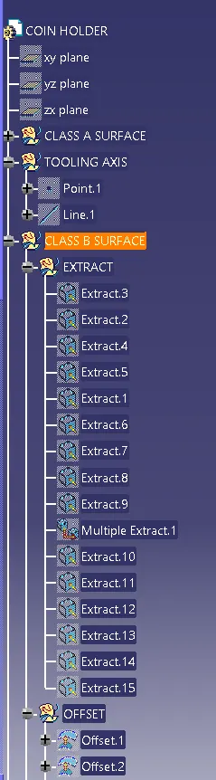
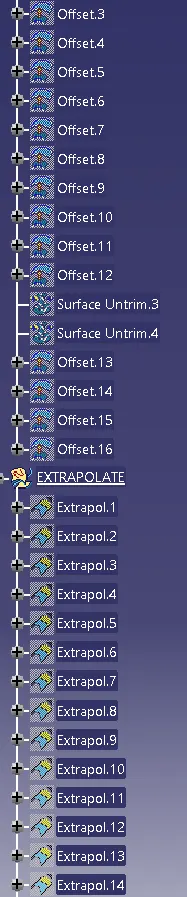
- For creating the class-B surface the required surface except the offset surface have been extracted and then untrimmed all the surface.
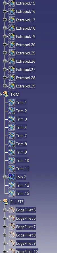
- Then all the surfaces have been extrapolated to get intersections between them.
- Since the thickness of the COIN HOLDER is 2.5mm the B-Surface was offset to 2.5 mm and the required trim operations must be carried out.
CREATION OF CLASS – C SURFACE
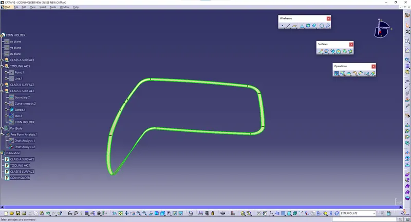
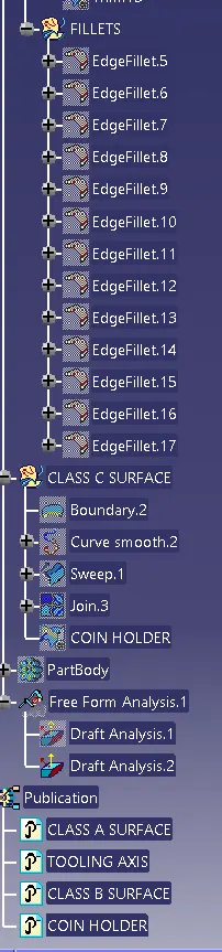
- The required outer edges of the A-Surface were extracted using Multiple Extract. Then for avoiding the patches the curve is smoothened using the Curve Smooth option.
- Then by using the sweep command the surface was created with the following feature controls.
CREATION OF CLOSED SURFACE:
- Now the class – A and Class- C surfaces were joined together by removing the gaps in-between them with the help of extrapolate and Trim surface.
- Then the exact surface of the COIN HOLDERl was trimmed from the above-resulted trim surface with the class-B surface.
- Then, by defining the part body by using the Closed Surface command in Part Design, the component's solid body is created.
PROCEDURE FOR DRAFT ANALYSIS
- First the class – A surface is checked before creating the Class surface and finally the solid body must be analysed. Both can be done by following the below procedures.
- By changing the view mode to custom view parameters – Material mode then the feature draft analysis is enabled.
- Then the compass was activated and placed with the tooling axis by dragging the red pointer and then locked it.
- Then, by selecting the quick analysis mode, the nominal value will be 3 degrees and checked for the component's draft angle.
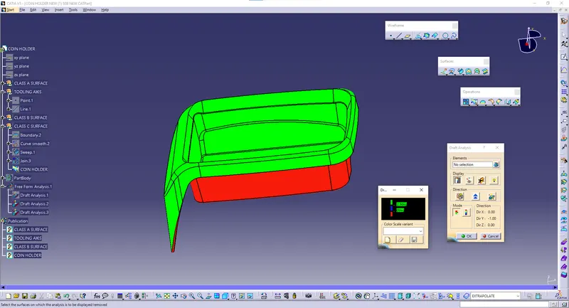
- The green colour area shows that it satisfies the 3-degree draft angle. If not satisfied then by using the Running point tool the area is measured and then altered to get a successful draft for the created tooling direction.
CONCLUSION IMAGES
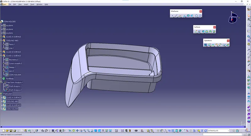
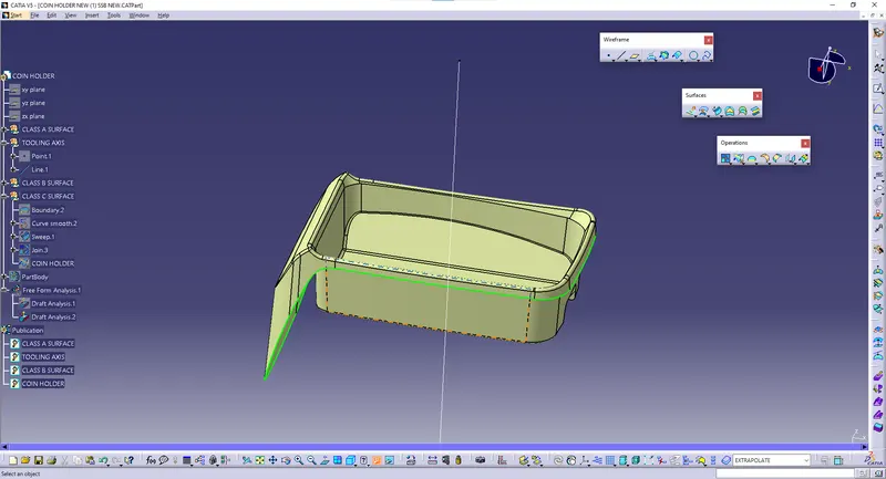
Finally the Class – A, B&C surfaces with the Tooling Direction have been Published and the COIN HOLDER is moved on to the designing of the next operation – the creation of B-side features.