Roof Design
AIM :
To Create the car's roof using the given class A surface with the Given Guidelines of OEM.
ROOF :
An automobile roof is considered an integral part of BIW (body in white) design. A car roof is responsible for protecting the passenger from rain, wind, sunlight, accidents, etc. It also offers aerodynamic support to the car when it is in motion. A roof panel assembly includes a roof outer panel/ditch area and inverted hat-like reinforcements rails that underlie the outer side edges of the roof outer panel. Roof rails are provided to give strength to the outer panel and also provide support to other commodities present in a car.
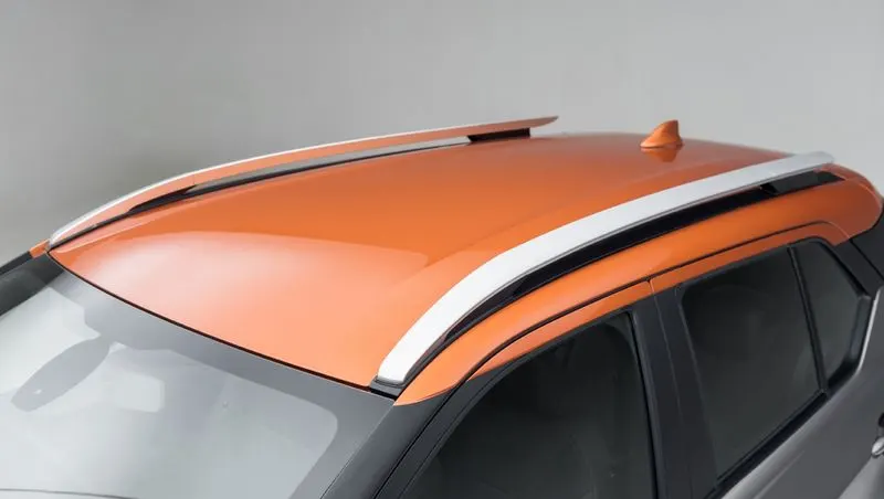
There are different rail reinforcements in a roof panel:
- Front roof rail
- Rear roof rail
- Bow roofs
- Ditch Area
Front roof rail:
The front roof rail is used to strengthen the roof panel front and acts as a link between windshield glass, roof panel, and headliner(interior trim). Headroom clearance and visibility are two important criteria for the driver and both of them depend upon the front roof rail dimensions, hence it is important to select appropriate dimensions for the roof rail.
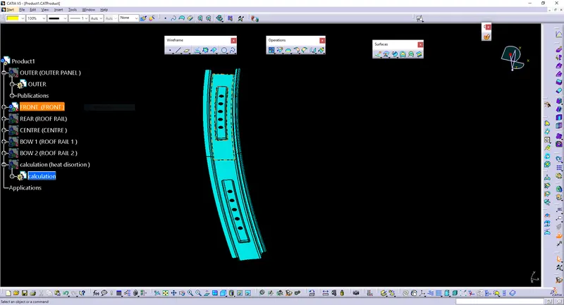
Rear roof rail
It is the support that is joined to the back door and the Body side outer and inner panels. it is usually made from body side outer scrap. We have to take into consideration the rear headroom clearance and the rear visibility criteria while designing the rear roof rail from the backdoor design and also take into consideration od the required clearance.
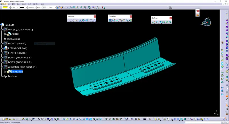
Bow Roof Rails
Similar to the other design, we have to take into consideration of the headroom clearance and the visibility criteria while designing the centre roof rail and bow roof rail. mastic sealants are used are introduced at both ends since centre Roofs are fully positioned under the styling surface of the roof. For increasing the strength of the rails. To reduce the weight of the material used, different styling has been followed with a thickness of 0.75mm.
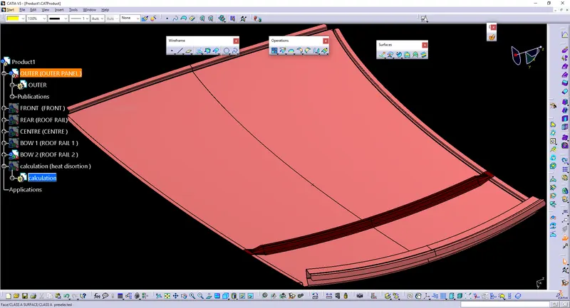
DESIGN CONSIDERATION-
- Visibility criteria
- Head clearance
- Curvature study
- Hear distortion and snow load criteria
- Draft analysis.
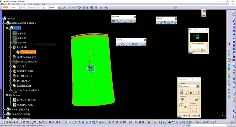
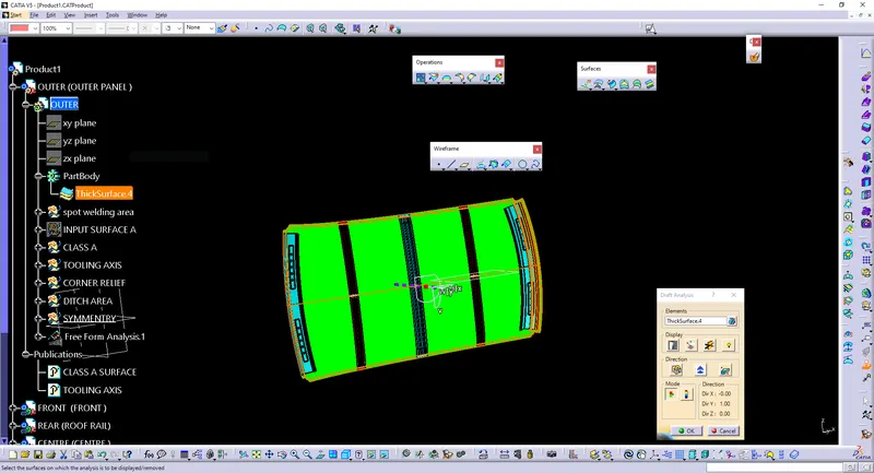
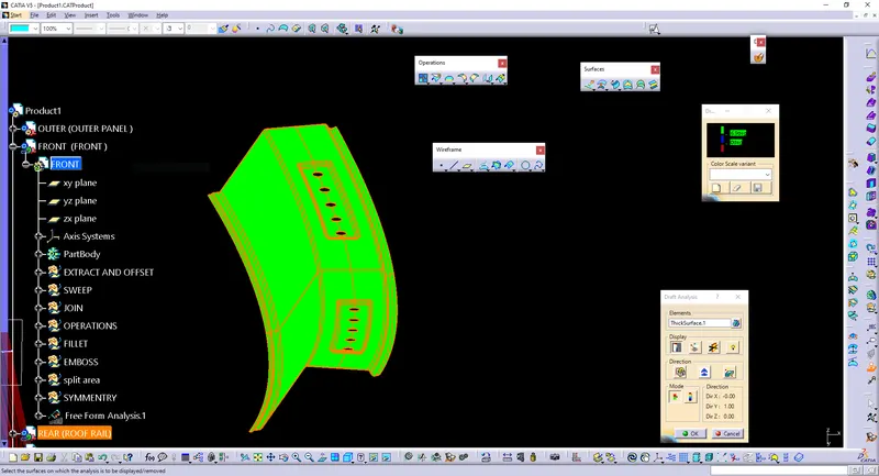
Calculations :
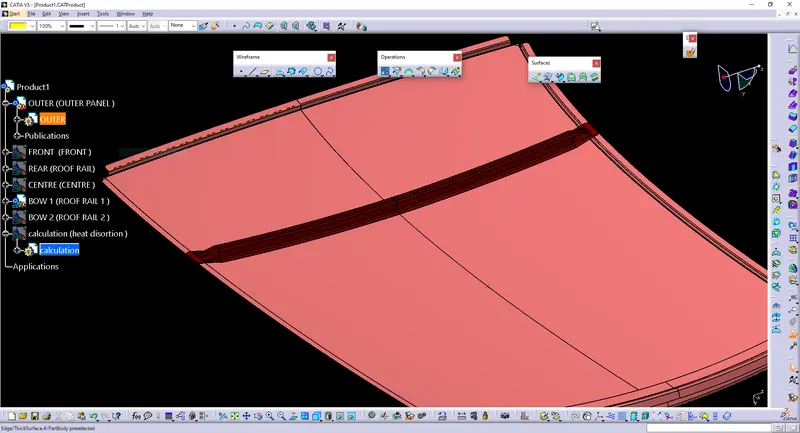
We then also make the ditch area around the roof.
Ditch area the extended portion of the main roof concealed by other BIW panels.
Bow–Roof Prediction Formula
W = [1.73 x 10^(-3) x L] + [1.85 x 10^(-8) x (R^2)/t] + [ 1.10x10^(-3) x l] - 2.68
Where,
L = Roof Length in X-Direction[mm](Roof dimension in 0-Y)
R = Roof curvature
R = 2(Rx*Ry)/(Rx+Ry)
Rx = X curvature
Ry = Y curvature
t = Roof plate thickness [mm]
l = Bow Roof Span [mm]
Judgment Condition-
OK< 2.7
| DISTANCE | X CURVATURE (Rx) | Y CURVATURE (Ry) | 2(Rx * Ry) | Rx+Ry | ROOF CURVATURE | LENGTH I | THICKNESS | TOTAL SPAN | W |
| SPAN1 FRONT-BR1 | 2468.249 | 5805.576 | 28659214.31 | 8273.825 | 3463.841006 | 329.689 | 0.75 | 2039.049 | 1.506168135 |
| SPAN2 BR1-CENTER | 6204.359 | 4974.502 | 61727192.51 | 11178.861 | 5521.778338 | 431.941 | 0.75 | 2039.049 | 2.074777425 |
| SPAN3 CENTER-BR2 | 10570.003 | 3994.826 | 84450645.61 | 14564.829 | 5798.258641 | 426.988 | 0.75 | 2039.049 | 2.146530051 |
| SPAN4 BR2-REAR | 14903.49 | 3271.715 | 97519943.57 | 18175.205 | 5365.548481 | 354.668 | 0.75 | 2039.049 | 1.947820962 |
Snow Load Prediction Formula
Qr = [Iy x t2] / [α x s x [(Rx + Ry)/2]2 x 10-8]
Note: The Qr value given over here is correct. There was a typo error in the formula given in the video.
Where,
α = My x Lx2 x 10-12 , My = Y(Ly-Y)
t = Roof plate thickness [mm]
Ly = Distance between the front and rear roof Rails on the Vehicle along with 0Y[mm]
Length of Roof panel with the center point between Roof rail Front /Rear as the front and rear reference point.
Lx = Distance between the Left and Right end of the roof on the Roof BOW [mm]
The width of the roof panel is exposed on the surface.
Y = Distance front Front Roof Rail to Roof BOW[mm]
s = Distance for which Roof BOW bears divided load [mm]
s = L1/2 + L2/2
Iy = Geometrical moment of inertia of Roof BOW (Y cross-section )[mm4]
Rx = Lateral direction curvature radius of roof panel Y cross-section on Roof BOW [mm]
Roof panel curvature Radius of the Length Lx in Front view
Ry = Longitudinal Direction curvature radius of the Roof panel X cross-section on Roof BOW [mm]
Roof panel X curvature radius of length s in Side view
Judgment condition
Qr ≥ 3.1
CONCLUTION-
- SINCE ITCOMES UNDER JUDGEMENT CONDITION IS SAFE.
- DESIGN IS SAFE
- TO SUPPORT THE 1 CENTER ROOF, 2 BOW ROOF IS ENOUGH.
- THE CONDITION Qr>3.1 IS NOT SATISFIED.
- THE ROOF MAY FACE BEND DUE TO SNOW LOADING, SINCE ITS NOT SATISFIED.
- OR IN ORDER TO MAKE THE ROOF STRONG WE CAN ADD EMBOSS TO THE OUTER ROOF.
- INCRESING THE EMBOSS DISTANCE, DUE TO CHANGEING THE SHAPE OF ROOF THE INERTIA VALUE WILL BE GREATER AND INCREASING THE THICKNESS OF THE BOW ROOF - THESE ARE THE WAYS TO SATISFY THE CONDITIONS.