Roof Design
OBJECTIVES:
1) Design a Roof with its components by following the master section of the front roof rail (at least 1 Front roof rail, two bow roofs, 1 center roof rail and 1 rear roof rail) with all the design parameter mentioned in the videos. Need to include all Part files and assembly file as a zip file along with the report.
2) Perform Draft Analysis for all the parts and include the snapshot in the report
3) Prepare a report which includes the curvature study on the roof based on the Bow roof prediction calculation as well as the manufacturing techniques.
ANSWERS:
ROOF & COMPONENTS:
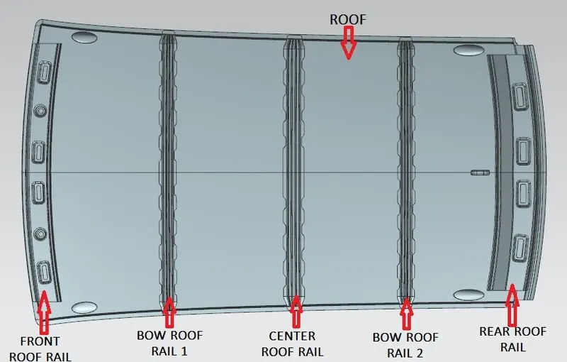
ROOF:
An vehicle roof is the portion of an automobile that sits above the passenger compartment, protecting the vehicle occupants from sun, wind, rain, and other external elements.
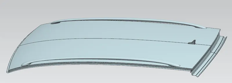
FRONT ROOF RAIL:
An front roof rail is located on the roof where wind shield will be going to be joined. The front roof rail is created as per the master section given. Front roof rail was created as per given mastersection. Embosses are given to increase the strength of the part.
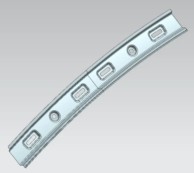
Fig: Front roof rail
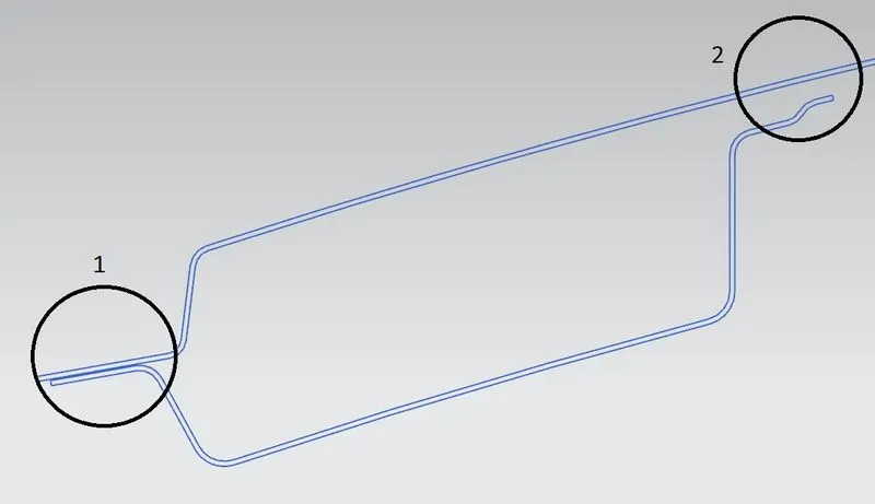
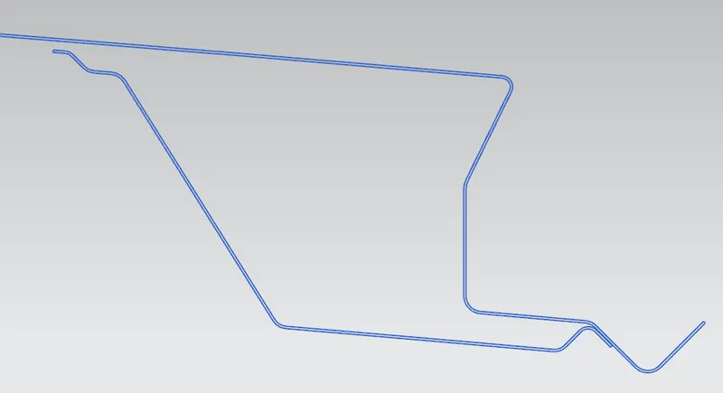
The front roof rail is joined with main roof by using spot welding and mastic methods. From the above image, Where point 1 is joined by using spot welding. Point no 2 where joint by using mastics, mastics are used because of aesthetic look of the outside roof. Spot welding gives weld marks on the surface.
BOW ROOFS:
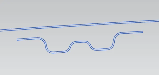
Bow roofs are used for incresing stiffness of the roof structure. Bow roofs are created as per given mastersection. Both bow roofs are looking similar, but the location of the bow roofs were different. Here bow roof 1 and bow roof 2 were located between center roof rail.
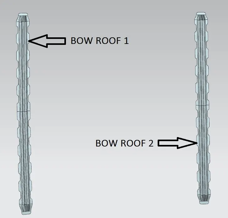
Fig: Bow roofs
CENTER ROOF RAIL:
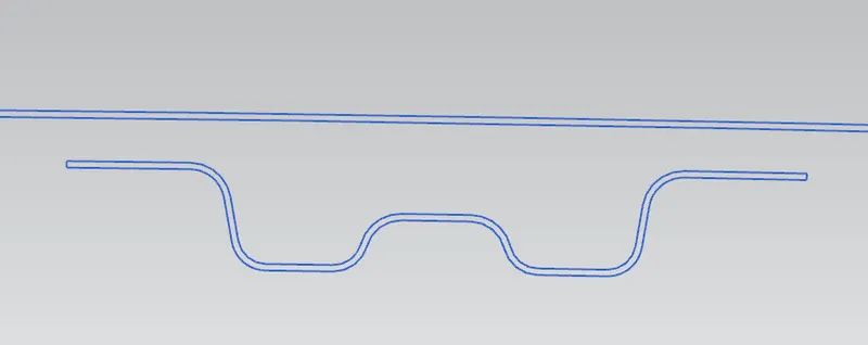
Center roof is used to strengthen the roof. Center roof is created as per mastersection given.
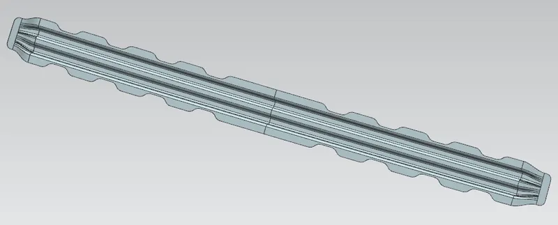
Fig: Center roof rail
REAR ROOF RAIL:
Rear roof rail is connected with back door of the vehicle. Rear roof rail is created as per the given master section. Embosses are provided to increasing the strength of the rear roof rail.
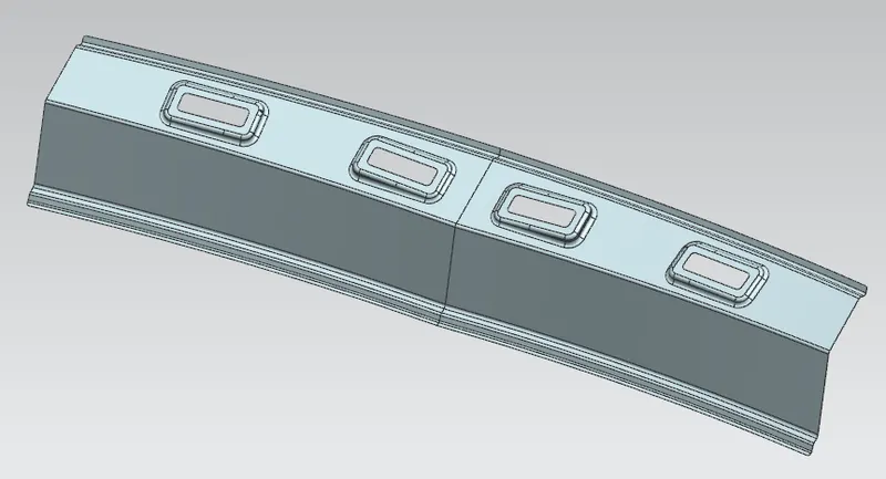
Fig: Rear roof rail
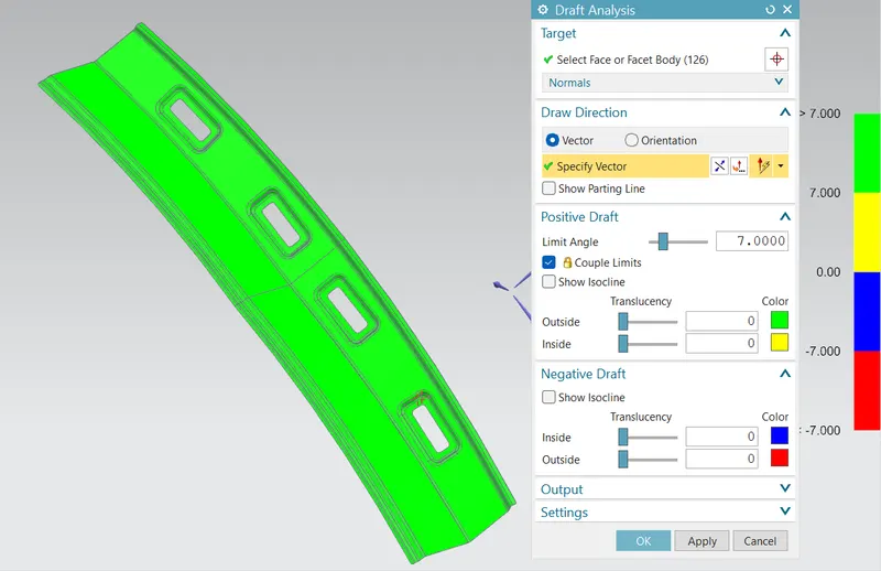
DRAFT ANALYSIS:
FRONT ROOF RAIL:
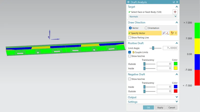
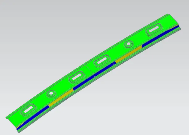
Note: Above portion in blue and yellow were not cleared in draft analysis.
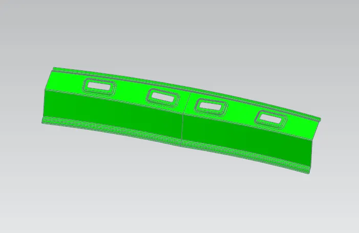
REAR ROOF RAIL:
Rear roof rail is cleared in draft analysis.
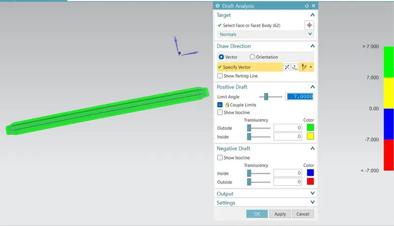
BOW ROOF RAIL 1:
Bow roof rail 1 is cleared in draft analysis.
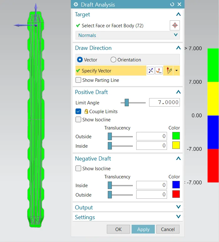
CENTER ROOF RAIL:
Center roof rail 1 is cleared in draft analysis.
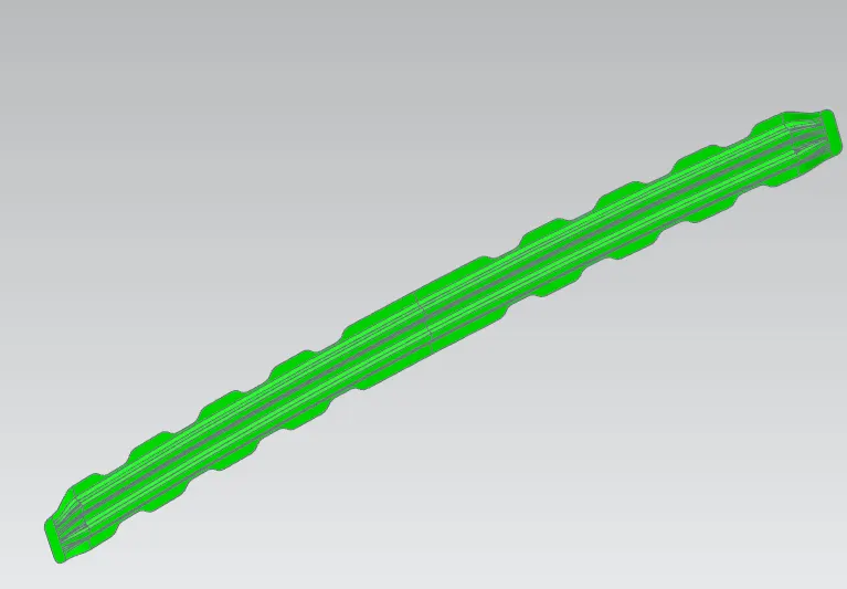
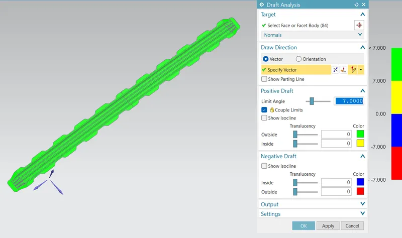
BOW ROOF RAIL 2:
Bow roof rail 2 is cleared in draft analysis.
OUTER ROOF PANEL:
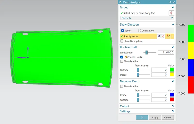
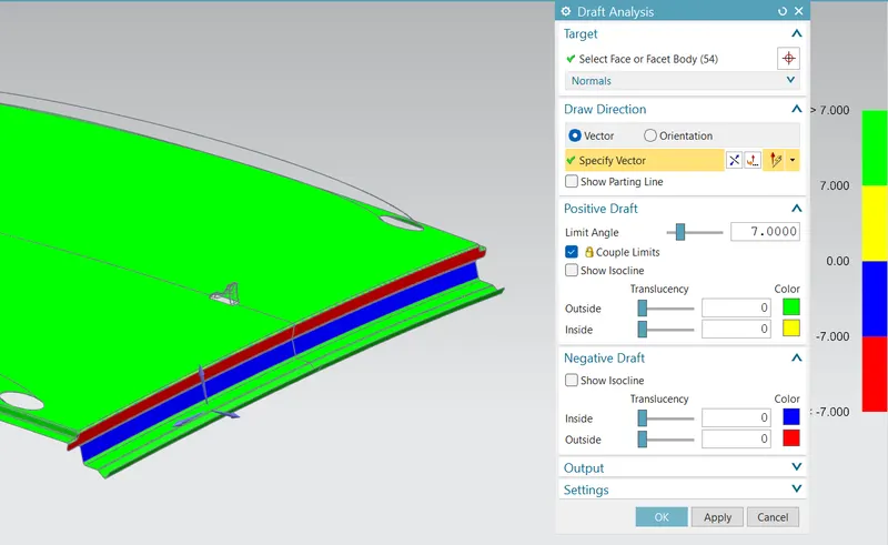
Note: Abover portions in red and blue were not cleared in draft analysis, remaining portions are cleared.
CURVATURE STUDY ON THE ROOF:
- HEAT DISTORTION CALCULATION
- SNOW LOAD CALCULATION
HEAT DISTORTION CALCULATION:
Heat distortion is temperature limit above which material cannot be used for structural application. This study is useful to find, where the material starts to soften when exposed to a fixed load at elevated temperature. In order to avoid the bending, damage to the roof based on the heat distortion temperature. This study will provide the which position of the bow roof give enough strengthen to roof design. This was calculated using bow roof prediction formula.
Bow–Roof Prediction Formula
W = [1.73 x 10^(-3) x L] + [1.85 x 10^(-8) x (R^2)/t] + [ 1.10x10^(-3) x l] - 2.68
Where,
L = Roof Length in X-Direction[mm](Roof dimension in 0-Y)
R = Roof curvature
R = 2(Rx*Ry)/(Rx+Ry)
Rx = X curvature
Ry = Y curvature
t = Roof plate thickness [mm]
l = Bow Roof Span [mm]
Judgment Condition
OK< 2.7
t=0.75 mm
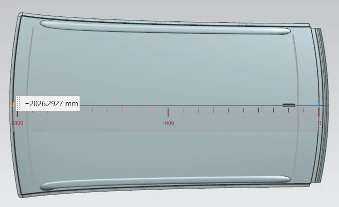
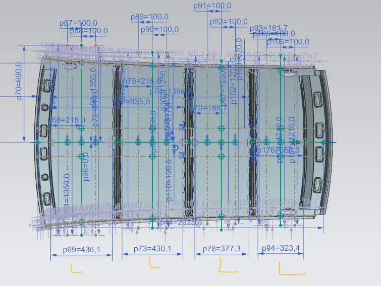
L = points were created in both ends of the roof and measured.
Rx & Ry= Rx & Ry was created by using following method
- create a sketch
- make a 0Y line in center
- make a 300 mm offset line parellel to 0Y
- make 100 mm offset line below and above
- create a vertical line in mid point of two bows
- create a points in the intersecting lines
- create a arc in that points
- measure the arc value.
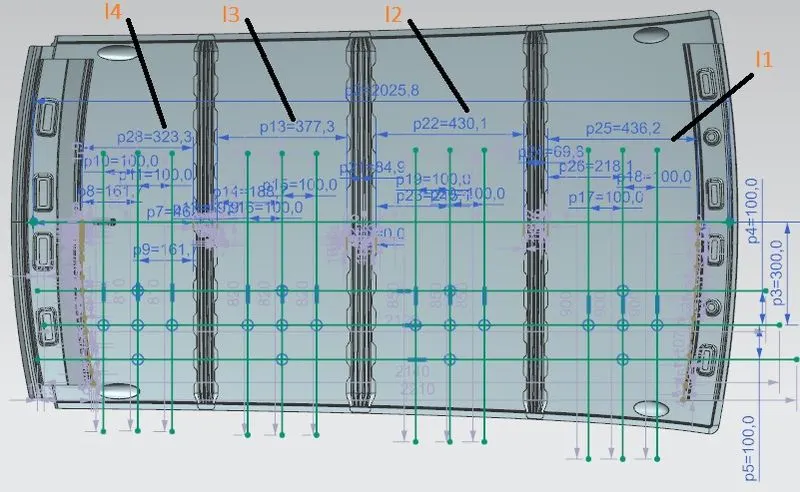
Now putting, All the points in the excel sheet and applying the formula we got bow roof judgement condition.
| SL. NO | BOWS | RX | RY | Rx*Ry | Rx+Ry | R | l | L | t | R^2/t | W | OK/ NG |
| 1 | FR & 1ST | 5727.12 | 2712.55 | 15535099.36 | 8439.67 | 3681.447108 | 436.177 | 2026.29 | 0.75 | 3231341369 | 1.64 | OK |
| 2 | 1ST & CTR | 4851.69 | 6677.6 | 32397645.14 | 11529.29 | 5620.059023 | 430.147 | 2026.29 | 0.75 | 9984101887 | 2.08 | OK |
| 3 | CTR & 2ND | 3922.69 | 10857.26 | 42589665.23 | 14779.95 | 5763.167701 | 377.259 | 2026.29 | 0.75 | 10676527404 | 2.06 | OK |
| 4 | 2ND & RR | 3291.970 | 14503.99 | 47746699.96 | 17795.96 | 5366.015653 | 323.302 | 2026.29 | 0.75 | 8825483227 | 1.89 | OK |
From the above table we conclude that all the values of W< 2.7. which is fullfill the judgement condition. So, it confirms that all the bow roofs are placed correctly.
SNOW LOAD CALCULATION:
Snow load study is used to check the durability of the roof to withstand the snow fall on the roof and regain its original shape without any permanent deformation after load being removed.
Snow Load Prediction Formula
Qr = [Iy x t2] / [α x s x [(Rx + Ry)/2]2 x 10-8]
Note: The Qr value given over here is correct. There was a typo error in the formula given in the video.
Where,
α = My x Lx2 x 10-12 , My = Y(Ly-Y)
t = Roof plate thickness [mm]
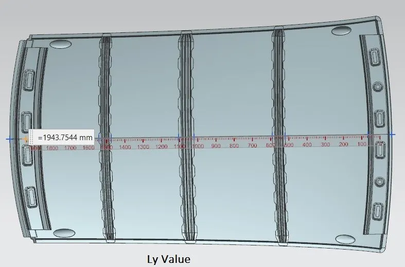
Ly = Distance between the front and rear roof Rails on the Vehicle along with 0Y[mm]
Length of Roof panel with the center point between Roof rail Front /Rear as the front and rear reference point.
Lx = Distance between the Left and Right end of the roof on the Roof BOW [mm]
The width of the roof panel is exposed on the surface.
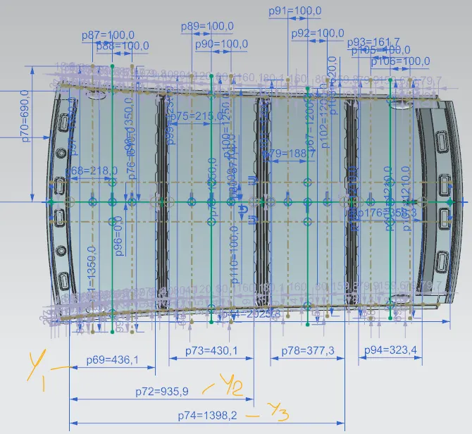
Y = Distance front Front Roof Rail to Roof BOW[mm]
s = Distance for which Roof BOW bears divided load [mm]
s = L1/2 + L2/2
Iy = Geometrical moment of inertia of Roof BOW (Y cross-section )[mm4]
Rx = Lateral direction curvature radius of roof panel Y cross-section on Roof BOW [mm]
Roof panel curvature Radius of the Length Lx in Front view
Ry = Longitudinal Direction curvature radius of the Roof panel X cross-section on Roof BOW [mm]
Roof panel X curvature radius of length s in Side view
Judgment condition
Qr ≥ 3.1
250 ≤ s ≤ 380
t=0.75 mm
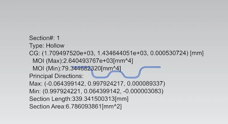
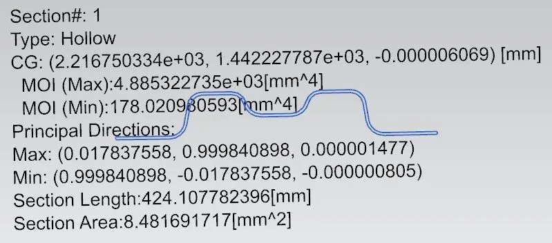
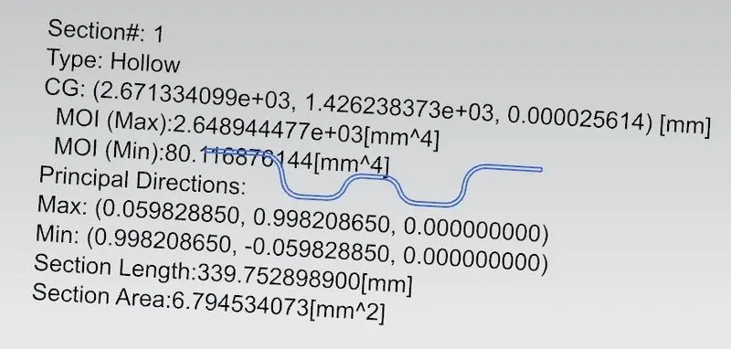
For measuring the moment of inertia for the bow roof and center roof we have to take the intersection of the part at the verticle center plane and using inertia analysis option to find out the moment of inertia value.
Bow roof 1 MOI
center roof MOI
Bow roof 2 MOI
Ly value measure from center of the front roof rail to center of the rear roof rail
Lx = Distance between the Left and Right end of the roof on the Roof BOW [mm]
The width of the roof panel is exposed on the surface.
Lx1
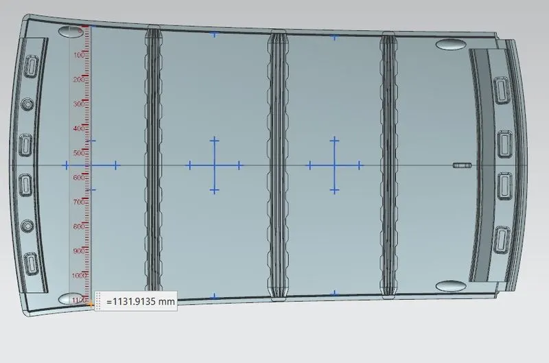
Lx2
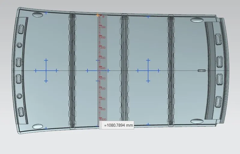
Lx3
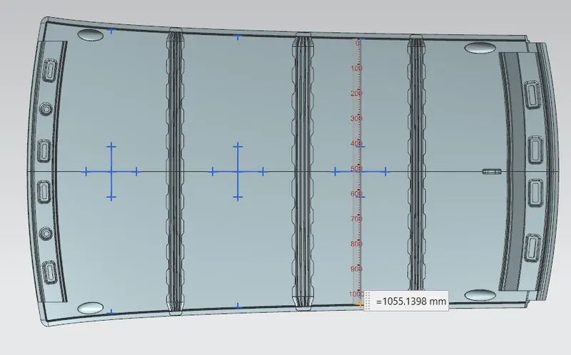
For taking L1 and L2 We take the values of first and second bow distance for each category
For measuring Y distance we have to take distance from front roof rail to bow roof 1, center roof rail and bow roof 2 value
Now, putting the all values in the excel sheet and applying the formula, then we have to get the result of snow load condition below table.
Condition 1 (MOI(min) value)
| SL. NO | BOWS | Iy | Ly | Lx | L1 | L2 | Rx | Ry | Y | My | t | α | s | Qr | OK/NG |
| 1 | FR & 1ST | 79.34 | 1943.75 | 1131.91 | 436.05 | 430.09 | 4427.88 | 2752.65 | 436.05 | 657432.6 | 0.75 | 0.84 | 433.07 | 0.95 | NG |
| 2 | 1ST & CTR | 178.02 | 1943.75 | 1080.79 | 430.09 | 377.31 | 3794.02 | 6607.91 | 935.92 | 943248.3 | 0.75 | 1.10 | 403.7 | 0.83 | NG |
| 3 | CTR & 2ND | 80.12 | 1943.75 | 1055.14 | 377.31 | 323.4 | 4297.76 | 11422.85 | 1398.15 | 762830.6 | 0.75 | 0.85 | 350.36 | 0.25 | NG |
In this condition 1 we will not achieve snow load criteria. For achieving snow load condition we have to do modification in the design, like increse the height of the roof bows, maintain Distance for which Roof BOW bears divided loads [mm] (s).
Condition 2 (MOI(max) value)
| SL. NO | BOWS | Iy | Ly | Lx | L1 | L2 | Rx | Ry | Y | My | t | α | s | Qr | OK/NG |
| 1 | FR & 1ST | 2640.49 | 1943.75 | 1131.91 | 436.05 | 430.09 | 4427.88 | 2752.65 | 436.05 | 657432.6 | 0.75 | 0.84 | 433.07 | 31.59 | OK |
| 2 | 1ST & CTR | 4885.32 | 1943.75 | 1080.79 | 430.09 | 377.31 | 3794.02 | 6607.91 | 935.92 | 943248.3 | 0.75 | 1.10 | 403.7 | 22.84 | OK |
| 3 | CTR & 2ND | 2648.94 | 1943.75 | 1055.14 | 377.31 | 323.4 | 4297.76 | 11422.85 | 1398.15 | 762830.6 | 0.75 | 0.85 | 350.355 | 8.11 | OK |
In this condition 2 we can cleared snow load condition.
Manufacturing techniques:
- Vehicle roofs are manufactured from sheet metal, roof shapes are done by using stamping method.
- The non visible areas were generally weldes by using spot welding method.
- Other visible areas were joined by using mastic sealents.
CONCLUSION:
I designed a Roof with its components by following the master section of the front roof rail, two bow roofs, 1 center roof rail and 1 rear roof rail with all the design parameter mentioned in the videos. I did Perform Draft Analysis for all the parts and attached the snaps in the answer box. Then I Prepared a report which includes the curvature study on the roof using heat distortion calculation and snow load calculation. Here i have got cleared heat distortion criteria, But not clearing the snow load criteria in minimum moment of inertia value and clearing it with maximum moment of inertia value. For this i have to redesign the bows to achieve the better snow load condition.
Thanks.