Roof Design
ROOF DESIGN
INTRODUCTION:
Every product's design begins with a requirement. Based on the requirements, the design engineer creates a sketch of the product. Then, using CAD software, the 2D sketch with the right measurements is turned into a 3D model. Every developed product must be manufacturable. As a result, the design engineer's role is to create products that are simple to construct and low in cost. The design is developed until it meets the needs of the client. In this project, a car roof is the final product that will be created.
OBJECTIVE:
- Create an assembly by devloping the essential flanges for the outer roof and creating the reinforcement.
- Provide appropriate dimensions and check for Draft analysis.
- Do a curvature study on the roof and perform calculations to determine the position of the Bow-roofs.
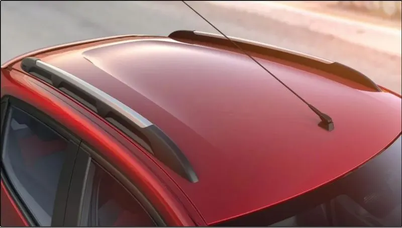
Image 1: Car Roof Image.
THEORY:
Car Roof:
A car's roof is the part that sits above the passenger area and protects the people inside from the sun, wind, rain, and other outside elements. The roof is the framework over the windscreen glass, and it is reinforced to strengthen the whole thing and withstand forces from above, like snow, rain.
Reinforcements
The front roof rail, centre roof rail, rear roof rail, and bow roof rail are introduced and linked to the flat surface of the roof using various joining processes in order to strengthen the strength of the roof. A flat roof is very weak and cannot sustain forces like snow.
- The roof has a decorative panel on the outside.
- The front roof rail, bow roof, centre roof rail, and rear roof rail are strengthening components found beneath an outer panel of a roof.
- The windscreen glasses have a place on the front roof rail. When designing the front roof rail, headroom requirements and visibility standards must be taken into consideration. The front roof rail has attachment holes for the inside rearview mirror and windscreen.
- The back door's hinge attachment is on the rear roof rail. It is fastened at the point where the roof and back door meet.
Between the front roof rail and the centre roof rail, as well as the rear roof rail and the centre roof rail, bow roofs are offered. - They are offered to improve the localised strength of the roof and are fixed directly to the underside using either spot welding or mastics.
- The centre roof rail or reinforcement centre is employed as a cross member between the left and right bodysides.
- The Master section has a front roof rail and a rear roof rail for the design. The location is shown in the picture below.
Roof Functionality and Design Requirements :
The following factors need to be taken into account while constructing a roof.
- Visibility Criteria.
- Head clearance.
- Heat distortion and snow load criteria.
- Draft Analysis.
As we know the outer glosy finish is known as roof top and let's see the inner components that are present inside a car's roof.
FRONT ROOF
The fore most point of the roof is called front roof. The windscreen glass, body side outer and inner panel are connected by the front roof rail. The front roof rails in this case are designed using the provided master section below, from master's section having measurement requirements we take some distance of offset to downward direction and hide the parent file and use needed commands to work on to further process.
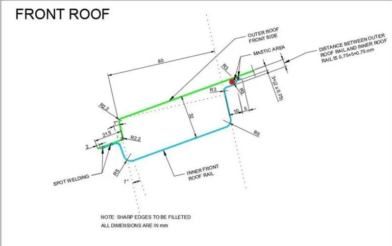
Image 2: Front Roof Master Section.
Like that is mentioned above, the part is done by 2D sketch and converting it to sheetmetal design with required commands. so from the given source we build the front roof part that is shown below.
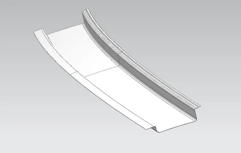
Image 3: Front Roof Part.
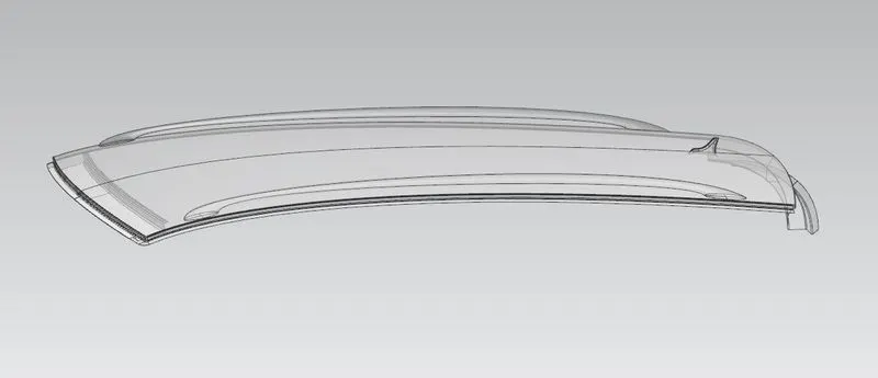
Image 4: Location of Front Roof Part.
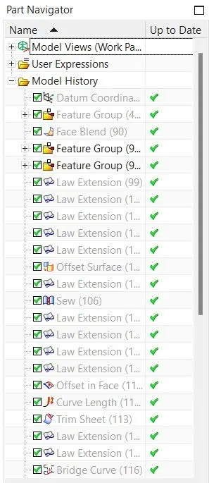
Image 5: Front Roof Part Navigator 1.
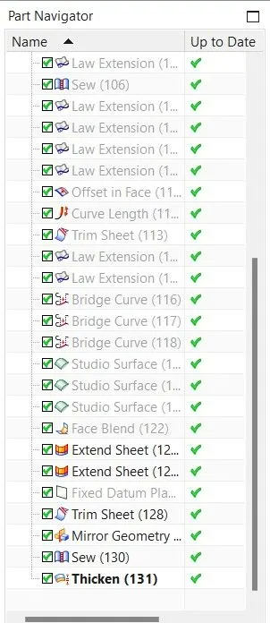
Image 6: front roof part navigator 2.
According to the master section and by using the NX12 software, the front roof part is successfully built.
REAR ROOF
The rear Roof Rail connects the back entrance to the exterior body side, fromt the master section given every dimensions were followed by with the face offset of the top like mentioned below in the pictures.
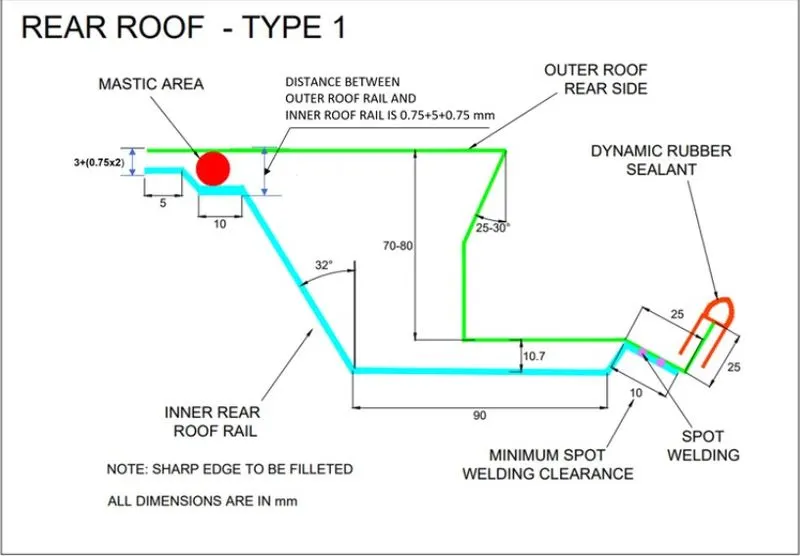
Image 7: Master Section of Rear Roof.
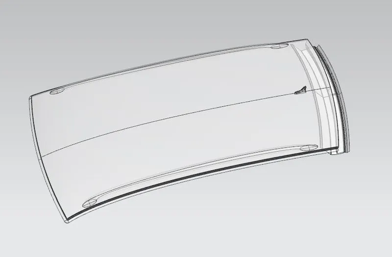
Image 8: Location of Rear Roof Part.
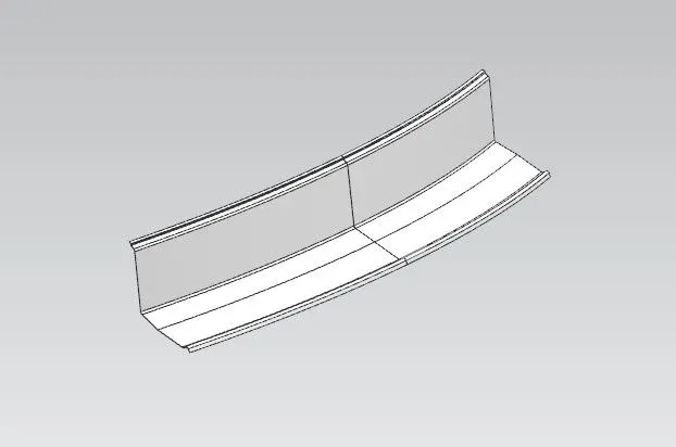
Image 9: Rear Roof Part.
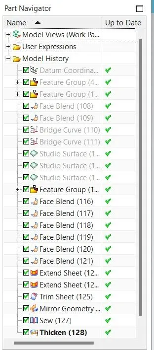
Image 10: Rear Roof Part Navigator.
According to the master section and by using the NX12 software, the rear roof part is successfully built.
BOW ROOF
The Bow roofs are provided to increase the roof structure's torsional stiffness and load-bearing capacity. The presence of bow roofs is dependent on the size of the roof as a whole. There are currently two bow roofs available in this project.
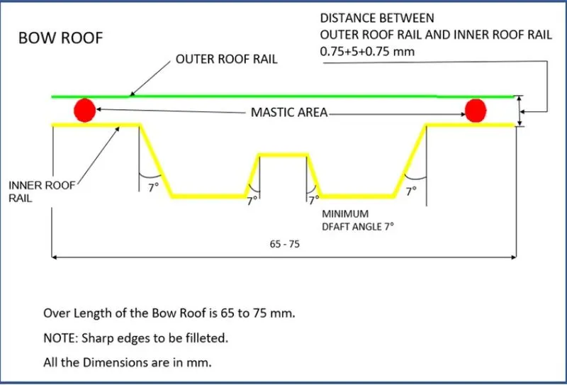
Image 11: Bow Roof Master Section.
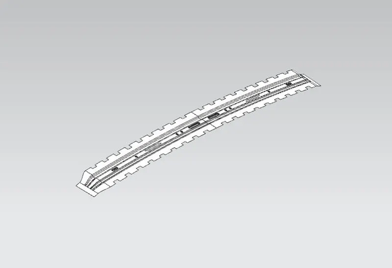
Image 12: Bow Roof Rail 1.
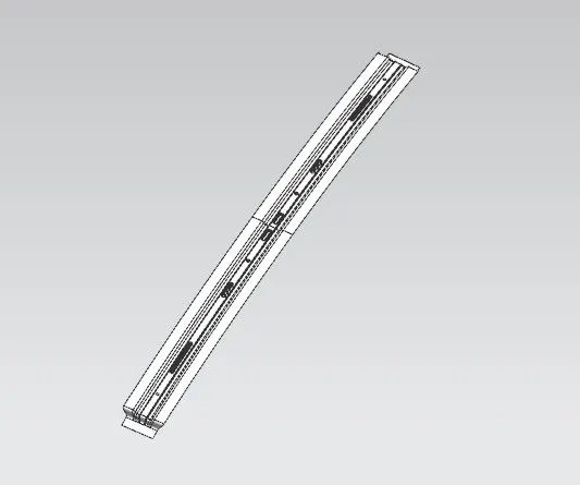
Image 13: Bow Roof Rail 2.
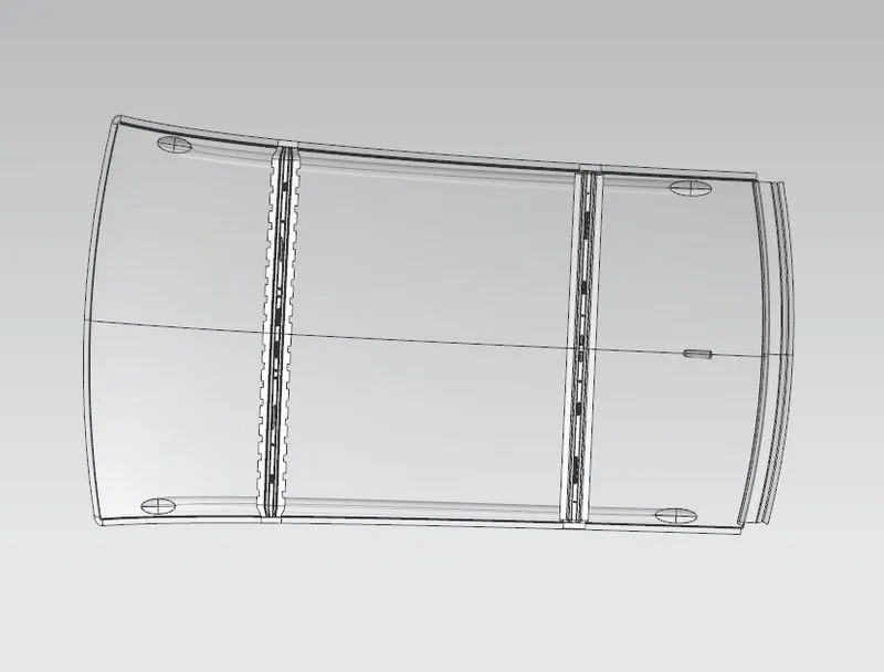
Image 14: Location of Both The Bow Roof Rails.
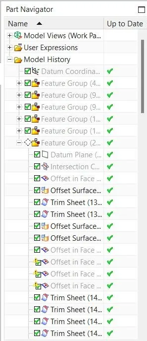
Image 15: Bow Roof Rail 1 Part Navigator 1.
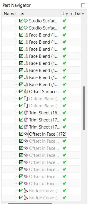
Image 13: Bow Roof Rail 1 Part Navigator 2.
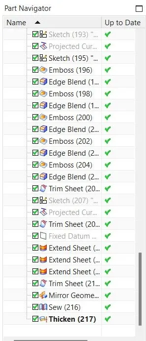
Image 14: Bow Roof Rail 1 Part Navigator 3
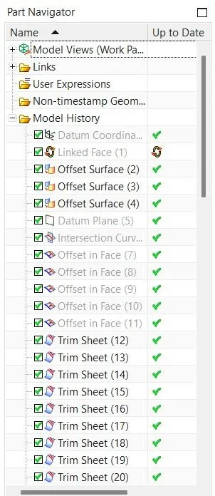
Image 15: Bow Roof Rail 2 Part Navigator 1
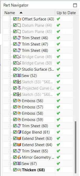
Image 16: Bow Roof Rail 2 Part Navigator 2.
CENTER ROOF
The central roof rail, which is often located at the centre of the roof and attached to the B-pillar support structure, aids in providing adequate support to the flat part of the roof, which is more prone to failure under the action of load. During the roll-over test, the central roof rail contributes to the roof's overall strength. It is constructed according to the master section given below.
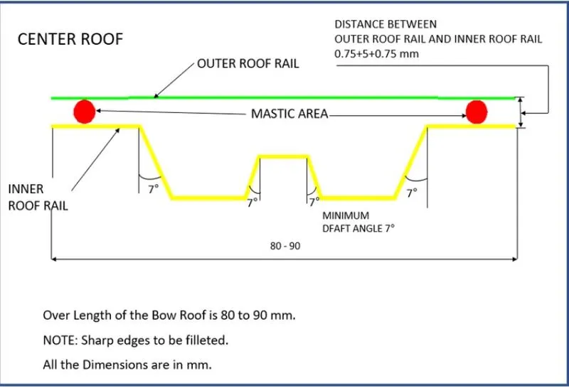
Image 17: Center Roof Rail Master Section.
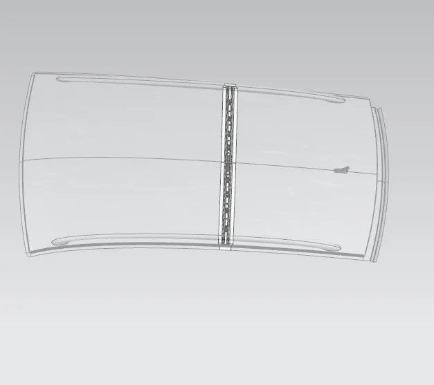
Image 18: Location of Center Roof Rail.
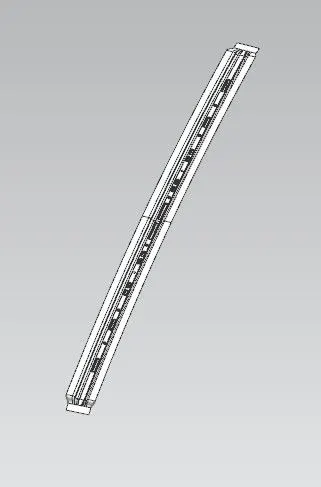
Image 19: Center Roof Rail Part.
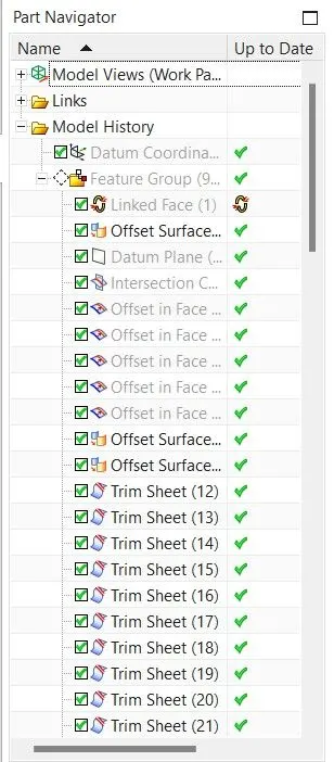
Image 20: Center Roof Rail Part Navigator 1.
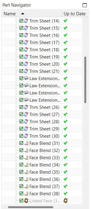
Image 21: Center Roof Rail Part Navigator 2.
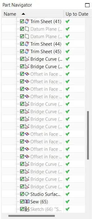
Image 22: Center Roof Rail Part Navigator 3.
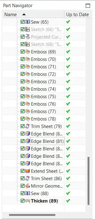
Image 23: Center Roof Rail Part Navigator 4.
According to the master section provided the center roof is successfully built using NX12.
ROOF ASSEMBLY
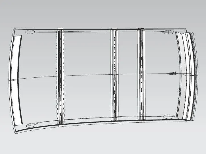
Image 24: Roof Assembly Image With Transparency.
Some factors that has to be followed in every parts.
- Before Mirroring them we have use extend sheet command and trim it even and in some cases the tangent curves selection won't let to select the entire curve so it's best to approach with single curve and make the selections.
- Some curves won't fit in the same command so deselect it and extend it in again but not int the same command choice, To be brief, use extend sheet again with same length and extend it.
- There's another problem that we might face in length issue that pops out at right corner so it can be rectified by changing the length.
- Sew the entire part and click on show results make sure there's no gap in the middle of any part, if found one then the problem lies on the extending sheet possibly.
- For Roof thicken it downwards and for rest of the parts upwards.
DRAFT ANALYSIS
The Draft analysis command determines if the part you drafted is easily removable. In this kind of analysis, zones on the investigated element are identified by colour ranges where the deviation from the draught direction at any given place corresponds to predetermined values.
REAR ROOF
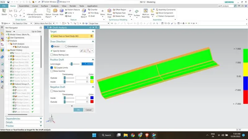
Image 25: Draft Analysis for Rear Roof.
Thus, the draft analysis was performed for rear roof part and it didn't had any issue and clear the test with positive draft of 7 degree with upwards vector, so the rear roof part is manufacurable.
BOW ROOF Rail 1
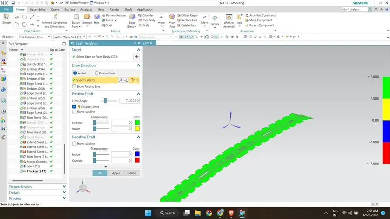
Image 26: Draft Analysis for Bow Roof rail 1
The draft analysis was performed for bow roof rail 1 and it didn't had any issue and clear the test with positive draft of 7 degree with upwards vector, so the bow roof rail 1 is manufacurable.
CENTER ROOF RAIL
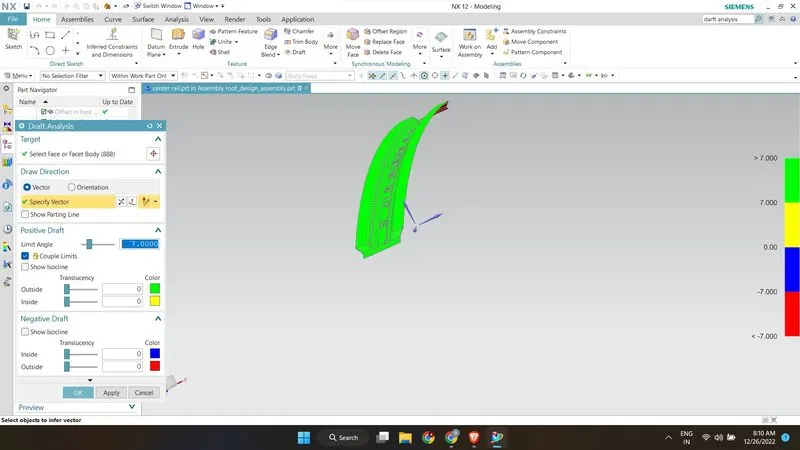
Image 27: Draft Analysis for Center Roof Rail.
The draft analysis was performed for bow roof rail 1 and it didn't had any issue and clear the test with positive draft of 7 degree with upwards vector, so the bow roof rail 1 is manufacurable.
BOW ROOF RAIL 2
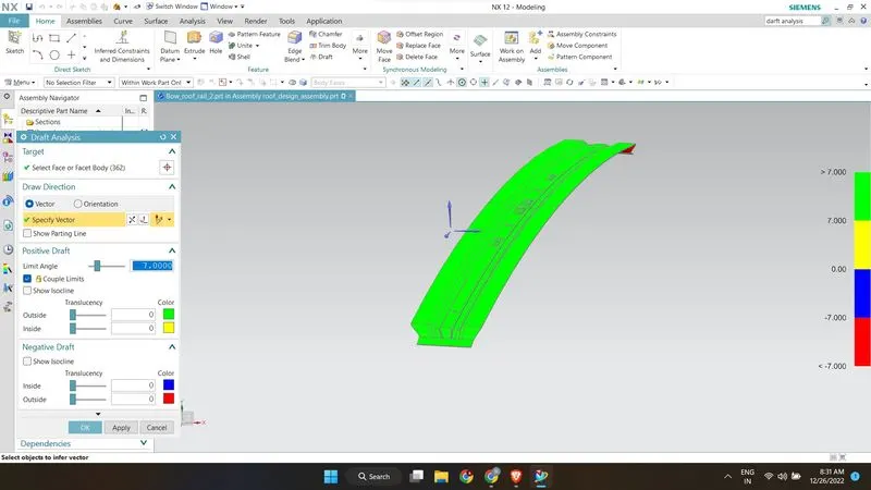
Image 28: Draft Analysis for Bow Roof 2.
The draft analysis was performed for bow roof rail 2 and it didn't had any issue and clear the test with positive draft of 7 degree with upwards vector, so the bow roof rail 2 is manufacurable.
FRONT ROOF
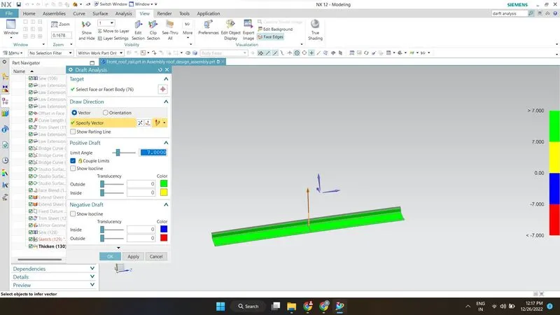
Image 29: Draft Analysis for Front Roof.
The draft analysis was performed for front roof and it didn't had any issue and clear the test with positive draft of 7 degree with upwards vector, so the front roof is manufacurable.
ROOF CRASH TEST
The IIHS's design for the roof crush test (Insurance Institute of Highway Safety). After reviewing numerous accidents, IIHS then made changes to the rules for conducting crash tests.
Based on this test, IIHS assigns the rating. When rating this, they take into account two points.
- How fast the car can go back to its original shape after it rolls over.
- How far out does it stick out after it rolls over.
The Roof Crush Test's objective is to reduce the protrusion into the occupant compartment as much as possible so that the airbags and seat belts can do their jobs of protecting the occupant.
Follow these guidelines for the roof crush test:
For the roof crush test, two prerequisites must be met -
- Lock all of the doors & Shut all of the windows.
- The second requirement is to fix the body sill or chassis frame horizontally on a hard surface.
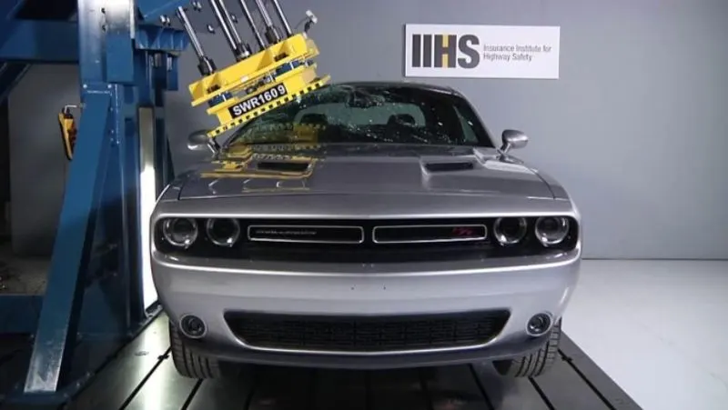
Image 30: Roof Crash Test.
Approach to Using Force
The load will be 1800 mm long and 750 mm wide and will be applied so that there is a 5 degree tilt from the front to the back. The load is placed at a 25-degree angle from the roof's flatness. The load is applied to the roof for almost 120 sec, and it is applied at a crushing speed of 13 mm/sec or less.
Result: If the displacement rises above the desired level, we must either add additional mastic points or thicken the bow roof to boost the structure's strength. In roll-over accidents, the stronger the roof, the more it can shield the occupants.
SECTION MODULUS
A geometric characteristic for a specific cross-section that is employed in the design of beams or flexural members is called section modulus. The radius of gyration for compression, the moment of inertia and polar moment of inertia for stiffness, and an area for tension and shear are other geometric properties employed in the design. Any correlation between these attributes depends largely on the geometry under consideration. Here are some equations for typical shape section moduli.
The elastic section modulus is defined as S = I/y
Where,
S = Section modulus
I = Moment of inertia
y = distance between the neutral axis and the end of the object
It is also often used to determine the yield moment (M y) such that M y = S X σ y
Where
σ y = yield strength of the material
M y = yield moment
Ʃ y for stainless steel is 520MPA
Calculation of the section modulus :
BOW ROOF 1
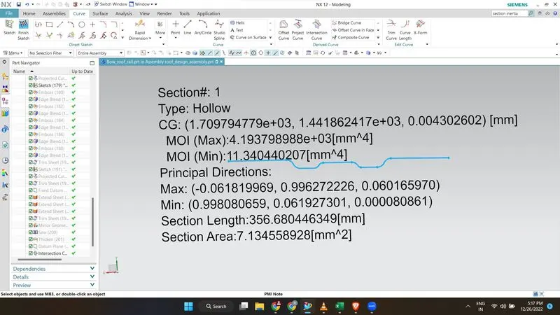
Image 31: Bow Roof 1 Section Modulus.
So we take MOI (min) = 11.3404 mm^4
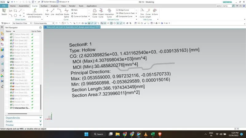
Image 32: Bow Roof 2 SectionModulus.
So we take MOI (Min) = 30.4858 mm^4
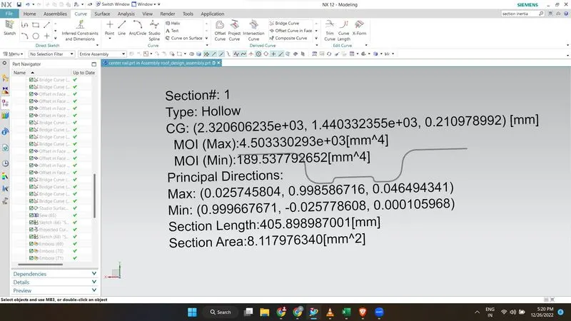
Image 33: Center Roof Section Modulus.
So we take MOI(min) = 189.5377 mm^4.
HEAT DISTORTION
Sheet metal desires are significantly influenced by the heat distortion analysis. The temperature below which a material cannot be used for structural purposes is known as the heat distortion temperature. Using this study, it is possible to estimate the temperature at which a material will begin to soften when subjected to a fixed load at a high temperature. Based on the heat distortion temperature, this study will forecast the bow roof position, which helps to strengthen the roof, to prevent bending or damage.
Bow - Roof Prediction Formula :
W = [ 1.73 X 10 ^(-3) X L] + [ 1.85 X 10^(-8) X (R^2)/t ] + [ 1.10 X 10^(-3) X1] -2.68
Where
L = Roof length in X -Direction (mm) (Roof dimension in 0-Y)
R = Roof Curvature
Where R = 2 ( Rx*Ry)/ (Rx+Ry)
Rx = X curvature
Ry = Y curvature
t = roof plate thickness (mm) =0.75 mm.
I = Bow roof span (mm)

Table 1: Heat Distortion Table.
From the above table, it can be concluded that all values of w<2.7 and also not w>3.1 so thus infer that the current positioning of the bow row is good in the state as per the design and found ok.
SNOW LOAD
This test is carried out to determine how the roof will function with snow on it. Typically, the dent will occur because of the weight of the snow. But the roof should be made so that it returns to its original position when the snow is removed. The snow load criteria's fundamental requirements are as follows.
Qr = [ Iy x t2] / [ α x s x [ ( Rx + Ry) / 2] 2 x 10⁻⁸]
Where
α= My x L x 2 x 10-12, My = Y (Ly - Y )
Judgement Condition = Qr ≥ 3.1
250 ≤ s ≤ 380
t = roof thickness [mm]
Ly = Distance between the front and rear roof rails on the vehicle along the OY [mm]
Length of Roof panel with the center point between roof rails front/ rear as the reference point of the front and the rear.
Lx = Distance between the left and right end of the roof on the Roof Bow [mm]
The width of the roof panel is exposed on the surface.
Y = Distance of front Roof rail to roof bow [mm]
s = Distance for which roof Bow bears divided load [mm]
s= L1/2 + L2/2
Iy = Geometrical moment of inertia of Roof Bow ( Y cross-section ) [mm4]
Rx = Lateral direction curvature radius of roof panel Y cross-section on Roof bow [mm]
Roof panel curvature radius of the length Lx in Front View
Ry = Longitudinal direction curvature radius of the roof panel X cross-section on Roof Bow [mm]

Table 2: Snow Load Table.
As we can see that Qr >= 3.1 didn't satisfy in the center rail - bow roof 2, Hence the design didn't pass the snow test.
RESULTS
- All the parts have successfully cleared the draft analysis.
- The proposed Roof design has successfully cleared the heat distortion analysis.
- The portion between center roof and bow Roof Rail 2is failed in Snowload analysis.
- The solution is to provide Embosses onto the roof outer panel portion where it is failing in snowload analysis. Embosses increase the strength of the roof panel.
CONCLUSION
The roof has been successfully designed considering all the design Rules, Master sections, Manufacturing feasibility, Draft analysis, Heat distortion criteria, and snowload analysis.