Roof Design
| ROOF |
AIM
Design of the front roof rail, rear roof rail, and bow roof for the roof of the vehicles with the help of the given skin data of the roof according to snow load condition and hear distortion criteria.
Objective
- Study different type of the roof available in the market.
- Study about the heat distortion criteria to adjust the position of bows and center roof rail.
- Study about snow load conditions to check the strength of the roof according to bows positions.
| THEORY |
CAR ROOF
An automobile roof or car top is the portion of an automobile that sits above the passenger compartment, protecting the vehicle occupants from sun, wind, rain, and other external elementsl. Convertible roofs, Roof modules, Hardtops, Sunroofs, T-tops, Targa tops, Vinyl roofs are the different type of roofs in Automobile.nowadays there are at least three types of roofs commonly installed on cars, namely sunroofs, moonroofs, and also panoramic roofs.
The roof of the car must have high strength to resist the crush force to avail the passenger some space for survival.
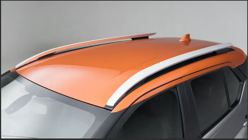
fig 2.1 car roof of different cars
ROOF PARTS AND STRUCTURE
The main parts of car roof is roof panel ,front roof rail ,rear roof rail,and bow roofs .Car roof parts shown in the fig 2.2 . basicaly there are 3 primary roof rails in a car the front, the centre, and the rear, and the additional roof rails are called Bow roof rails.Position and number of reinforcement is based on the structure and size of the roof .
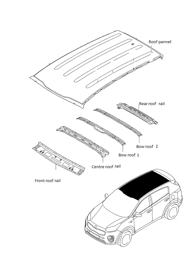
Fig 2.2 roof parts
| ROOF DESIGN CONSIDERATION |
|
|
|
|
|
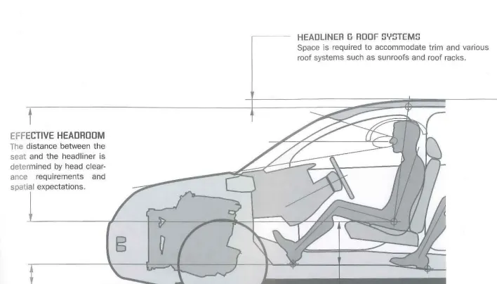
while designing the roof panel head room clearence and visibility criteria should be consider.based on this criteria proper angle and length provided for roof parts.
 |
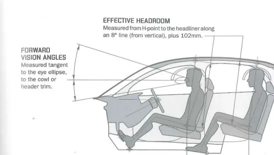 |
fig 2.3.0 head clearence and visibility
| ROLLOVER TEST |
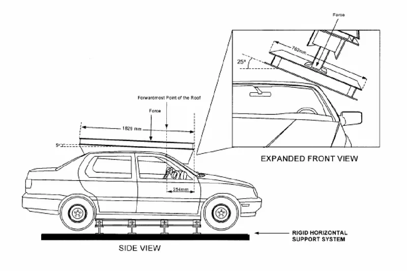
Rollover crashes, especially in the country, are usually very destructive events. Vehicle damage often includes deformation of the roof and its supporting structures. Head and neck injuries are common, and associated with roof deformation. Strengthening of the roof is suggested as an appropriate countermeasure for such injuries.Rollovers tend to be very severe crashes because of the energy required to roll a vehicle over unlike front and side crashes. This study is an effort towards reducing the severity of a rollover crash by strengthening the roof of a passenger car. The main focus of this thesis is to study the effect of reinforcing the roof of a car, in the event of a rollover.
Actual test conducted by National Highway Traffic Safety Administration(NHTSA) for rollover of the vehicle to check the roof strength :
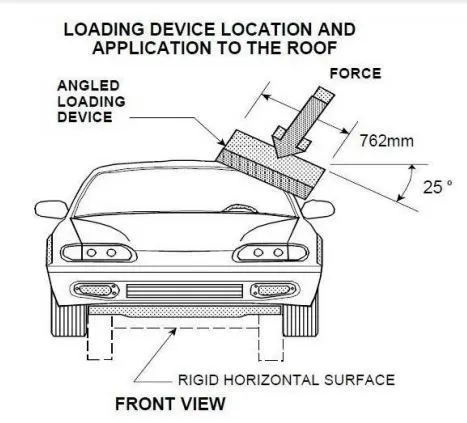 |
fig.2.3.1 rollover test
If the displacements goes above the requirements level then we have to increase the bow roof thickness or add more mastics points to increase the strength . the stronger the roof the better it can protect the occupants in the roll over crashes.
heat disortion and snow load criteria calculation is used to provide proper reinforcement to roof .The position and number of bow roofs based on this criteria.
| Methodology for designing the parts of the Roof |
1.Selecting the type of roof from the above list for the given skin data of roof surface.
2.Deciding the number of bows using to support the roof surface according to conditions.
3.Selecting the joining method used to join the roof surface with the front roof rail. rear roof rail, central roof rail, and for bows.
3.Designing the front roof rail and rear roof rail according to the given master sketch.
4.Designing the central roof rail and bows(as required) according to the given master sketch.
5.Calculating the parameters required for heat distortion criteria and checking the values of distortion in the roof are within range or not.
6.If the value of distortion in the roof body is not within the range, we need to change the position of bows and central rail roof so that the distortion in the roof should be within range.
7.Next we have to do iteration for the snow load condition to check the strength of the roof again if the value from the snow load condition is not in the range we have to do modifications in the bows section area and their position on the roof body.
WHY REINFORCEMENTS
If the roof is flat it is very weak and cannot able to with stand the forces like snow , so in order to increase the strength of the roof these reinforcements like front roof rail, central roof rail, rear roof rail and the bow roofs are introduced and joined to the flat surface of the roof with the different joining process
| Design Consideration and criteria |
| ROOF PANEL AND DITCH AREA |
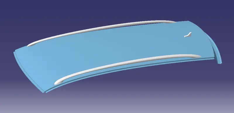
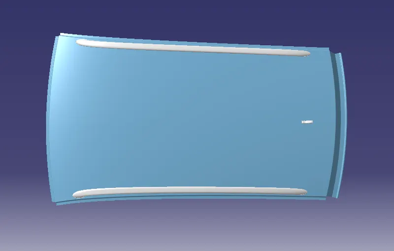
It is the outer surface designed by the styling team for the aesthetics of the vehicle.while design the roof ditch area visibility criteria should be consider based on this criteria proper open angle and length provided to front ditch area .windshield clearance and back door clearance also consider for designing of roof.bow roofs and centre reinforcement rails joined to ditch area by spot welding.
a.We are making the hardtop type of roof from the given master section so we are not adding any reinforcement for the central roof rail.
b.We are adding the flanges to all sides of the roof for spot welding of the front roof rail, central roof rail, rear roof rail, and bows.
c.The length and angle of the flange are decided based on the visibility criteria and according to the draw angle required for manufacturing the sheet metal.
d.The thickness of the roof is decided 0.75mm
|
|
| FRONT ROOF RAIL |
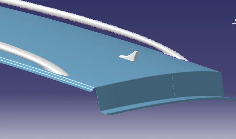
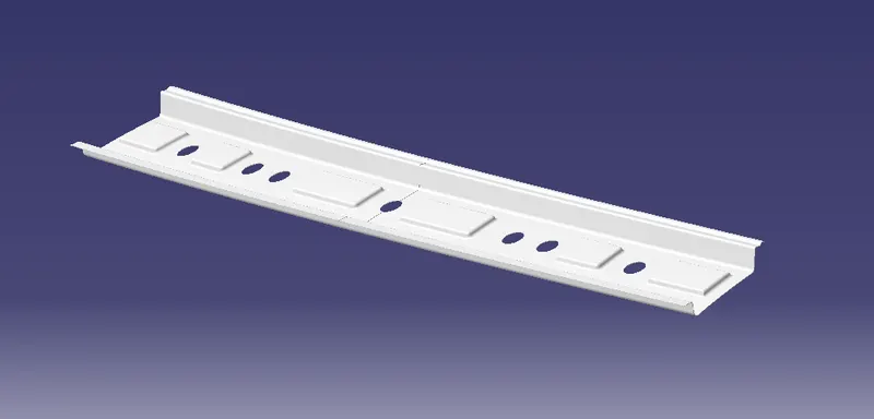
Front roof rail design based on Head room clearence and visibility criteria.it provides mounting provisions to windshield glass.one side of front roof rail joined by spot welding and the other end joined by mastic sealent ,so proper clearene provided for mastic.positive draft angle provided for undisturbed sheet metal forming process.There is no sharp corners in this design.Embosses are created to increase the strength of the roof rail.It is usually made from Body Side Outer scrap so thicknes of front roof rail is 0.75 mm .
a.The front roof rail is used as the reinforcement to the roof surface to increase the strength and also used to mount the brackets for some features such as room lamp or map lamp and rear mirror.
b.The depth of the front roof rail is decided based on the visibility criteria line decided for the driver visibility.
c.The width of the front roof rail is decided in such a way that there should be enough headroom clearance between the head of the driver and the end surface of the roof rail to avoid injuries to the person.
d.At the front side we are doing spot welding and on the rear side of the front roof rail, we are using mastic points to join it with the roof surface.
e. The minimum radius for the fillet at edges is 3mm
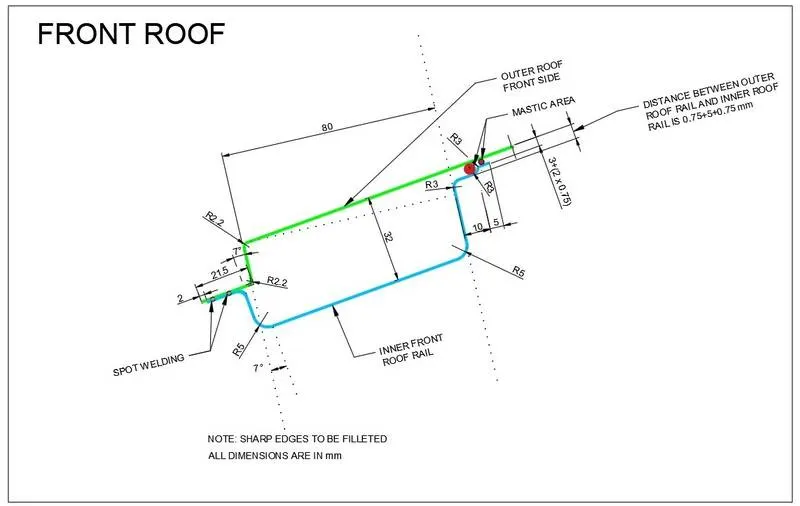
fig 2 master section for front roof rail
|
|
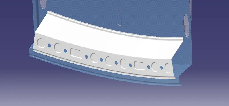
| REAR ROOF RAIL |
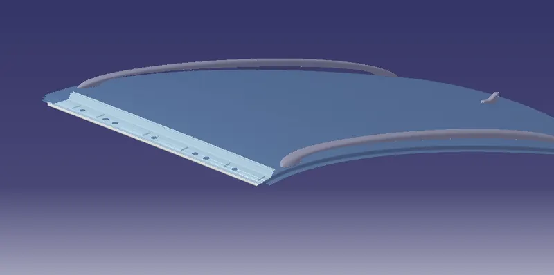
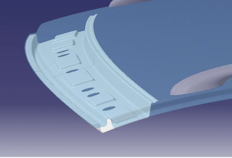
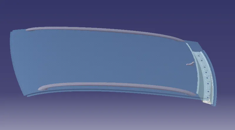
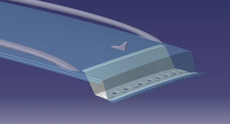
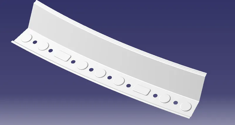
Head room clearence and rear visibility certeria should be consider while designing the rear roof rail. Appropriate draft angle is provided for trouble free sheet metal forming process.Inaddition accurate mastic and spot welding clearence provided in the design. Embosses are created to improve the strength of rear roof rail. one side of roof rail and roof joined by spot welding and the other end joined by mastic sealent.the thicknes of rear roof rail is 0.75 mm .
a.The rear roof rail is used as the reinforcement to the roof surface at the rear side.
b.The joining method used for this rail is the same as that of the front roof rail.
c.The minimum radius for the fillet is 3mm.
|
|
| BOW ROOF RAILS |
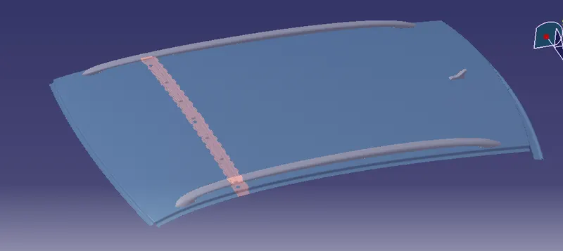
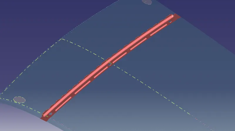
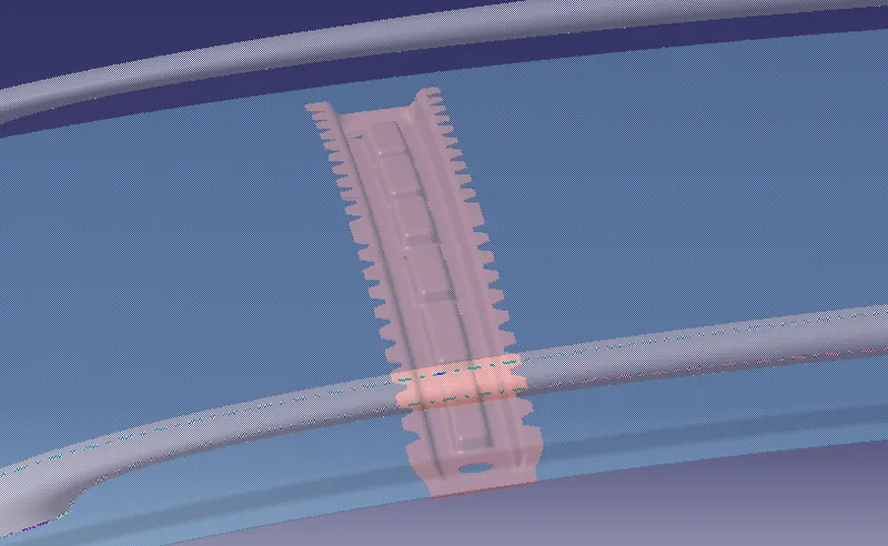
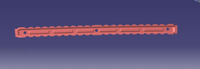
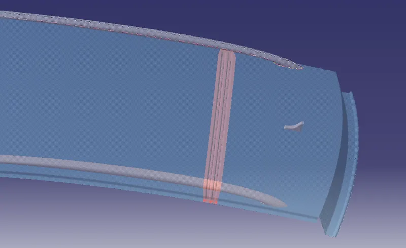
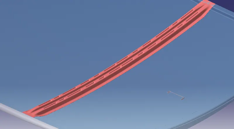
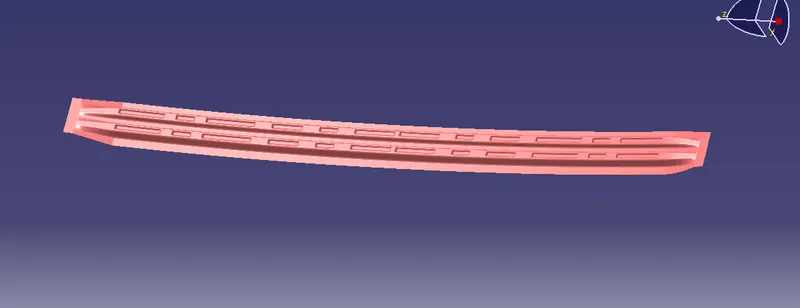
The bow roof rails provide additional support to the roof and they are positioned in such a way that they provide maximum support to the roof. The position of bow roof depends on the heat disortion and snow load criteria and curvature of roof .while designing the bow roofs head room clearence should be consider.Proper draft angle provided for uncomplicated sheet metal forming process. Bow roof fixed to roof with mastic sealent in addition ends spot welded to ditch area.
a.We are making two bows one is in between the front roof rail and central roof rail and another is in between the central roof rail and rear roof rail.
b.Both ends of the bow are joined to the roof outer flanges by the spot welding and the inner sides of the bow are joined to the inner surface of the roof with the help of mastic points.
c.The minimum radius of the fillet is 3mm.
d.The cross-section of the bow is made in such a way that we should get the maximum value of the minimum moment of inertia at which the bow fails.
BOWROOF 1 (FRONT)
|
|
BOW ROOF 2 (REAR)
|
|
| CENTRE ROOF RAIL |
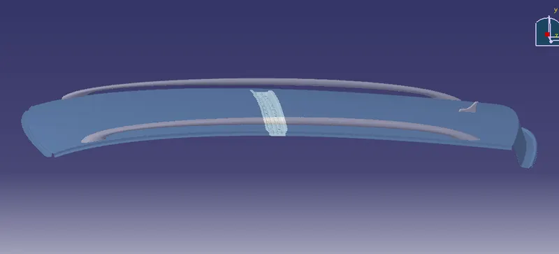
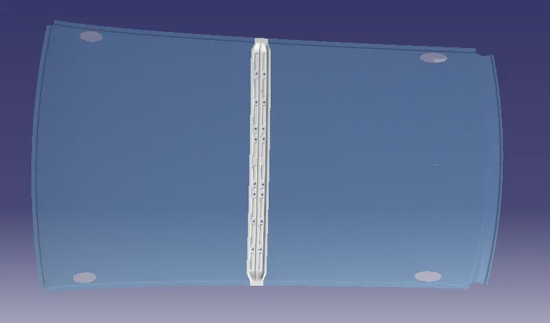
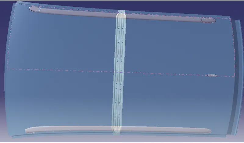
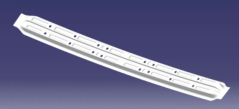
Centre roof rail is placed at the near centre of the roof to provide more strength and stiffness at the centre region. The position of centre roof rail also depends on the curvature of the roof .head room clearence and draft angle consider while designing the centre roof rail.it joined with roof by mastic and spot welding at the ditch area.The mastic points provided in the design .The thiknes of centre roof rail is 0.75 mm
|
|
| HEAT DISTORTION CRITERIA |
In this criteria, we check the heat distortion capacity of the roof at higher temperatures with the fixed load on it. So when the surrounding temperature is high and the roof is loaded with some weight on it then if the roof is deformed it fails, so to calculate whether the roof deform or not, according to the position of the bow we do these calculations as follows
Bow–Roof Prediction Formula
| W = [1.73 x 10^(-3) x L] + [1.85 x 10^(-8) x (R^2)/t] + [ 1.10x10^(-3) x l] - 2.68 |
Where,
L = Roof Length in X-Direction[mm](Roof dimension in 0-Y)
R = Roof curvature
| R = 2(Rx*Ry)/(Rx+Ry) |
Rx = X curvature
Ry = Y curvature
t = Roof plate thickness [mm]
l = Bow Roof Span [mm]
Steps to calculate the Heat distortions as follows:
1.First we offset the center y-axis line to 300mm distance apart from it represented as (-3Y to 3Y red line).
2.After that we offset this -3Y to 3Y to 100mm offset each side represented with the green line.
3.We draw the vertical red line at the center of the two consecutive bow rood span. Next, we offset this red line to 100 on each side.
4. Now we have three horizontal lines and three 12 vertical lines we take the intersection points of the vertical red line with three horizontal lines and a horizontal red line we take the intersection of the vertical lines with that line.
5.After getting all the points we project these points on the roof surface and draw the three points curve along the x-axis point to get the radius of curvature of Ry and along y-axis points to get the radius of curvature of Rx.
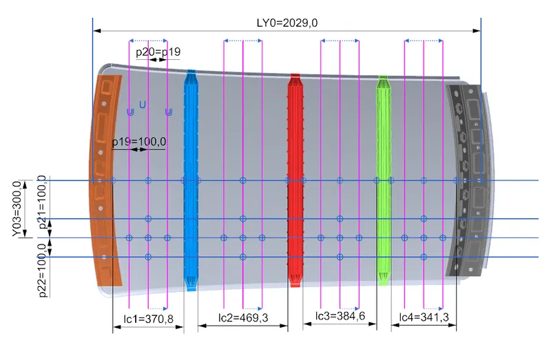
| SL.NO | SECTION | L(ROOF LENGTH) | Ry | Rx | R | t | l (bow roof span ) | W | REMARK |
| 1 | FRR-BR 1 | 2029 | 2560.6 | 5738.15 | 3541.04097 | 0.75 | 370.8 | 1.563577 | OK |
| 2 | BR1-CRR | 2029 | 6426.86 | 4915.22 | 5570.30647 | 0.75 | 469.3 | 2.127997 | OK |
| 3 | CRR-BR2 | 2029 | 10753.87 | 3943.74 | 5771.06989 | 0.75 | 384.6 | 2.090991 | OK |
| 4 | BR2-RRR | 2029 | 14553.89 | 3285.4 | 5360.67862 | 0.75 | 341.3 | 1.930675 | OK |
FRR- FRONT ROOF RAIL,BR- BOW ROOF ,RRR- REAR ROOF RAIL
In the above case all the value of "W" with in the judjment condition <2.7. so there is no modification needed.
| SNOW LOAD CRITERIA |
This snow load condition calculation is done to check the strength of the roof when there is dead weight on the roof. As we know that in some regions we have snowfalls so when snow falls on the roof then this act as dead weight because in some the rate of snowfall is more so the roof should sustain this dead weight for that we do this calculation to check the position of the bow and its sectional area.
Snow Load Prediction Formula
| Qr = [Iy x t2] / [α x s x [(Rx + Ry)/2]2 x 10-8] |
Note: The Qr value given over here is correct. There was a typo error in the formula given in the video.
Where,
| α = My x Lx2 x 10-12 , My = Y(Ly-Y) |
t = Roof plate thickness [mm]
Ly = Distance between the front and rear roof Rails on the Vehicle along with 0Y[mm]
Length of Roof panel with the center point between Roof rail Front /Rear as the front and rear reference point.
Lx = Distance between the Left and Right end of the roof on the Roof BOW [mm]
The width of the roof panel is exposed on the surface.
Y = Distance front Front Roof Rail to Roof BOW[mm]
s = Distance for which Roof BOW bears divided load [mm]
| s = L1/2 + L2/2 |
Iy = Geometrical moment of inertia of Roof BOW (Y cross-section )[mm4]
Rx = Lateral direction curvature radius of roof panel Y cross-section on Roof BOW [mm]
Roof panel curvature Radius of the Length Lx in Front view
Ry = Longitudinal Direction curvature radius of the Roof panel X cross-section on Roof BOW [mm]
Roof panel X curvature radius of length s in Side view
Judgment condition
Qr ≥ 3.1
250 ≤ s ≤ 380
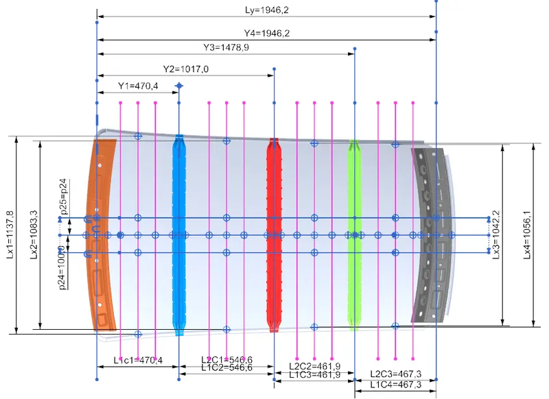
| SL.NO | SECTION | Y | Ly | My | α | Lx | L1 | L2 | S | ly | Rx | Ry | t | Qr | REMARKS |
| 1 | FRR-BR1-CRR | 470 | 1946.2 | 693814 | 0.89820386 | 1137.8 | 470.4 | 546.6 | 508.5 | 2199.34 | 4575.38 | 2537.61 | 0.75 | 21.41434 | OK |
| 2 | BR1-CRR-BR2 | 1017 | 1946.2 | 944996.4 | 1.10899003 | 1083.3 | 546.6 | 461.9 | 504.25 | 2288.5 | 3777.36 | 6355.72 | 0.75 | 8.967615 | OK |
| 3 | CRR-BR2-RRR | 1478.9 | 1946.2 | 691089.97 | 0.77080527 | 1056.1 | 461.9 | 467.3 | 464.6 | 2255.63 | 4289.53 | 11281.08 | 0.75 | 5.845414 | OK |
The above Snow load calculation Qr value with in the judgment condition Qr ≥ 3.1 .so here no altration required for the design .
| DRAFT ANALYSIS |
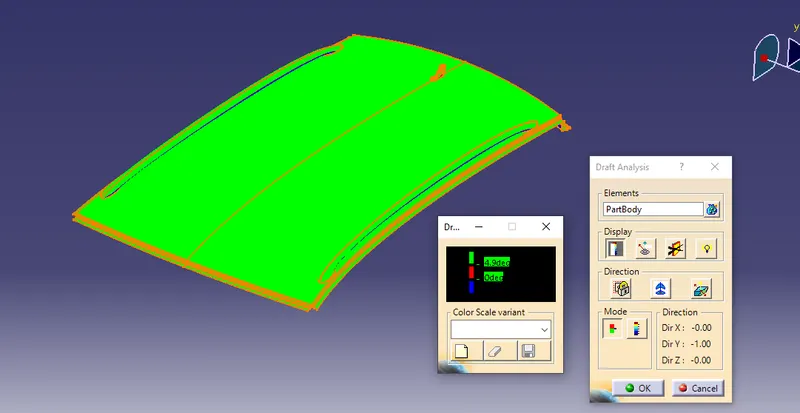
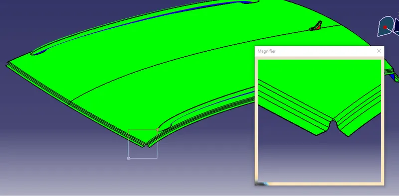
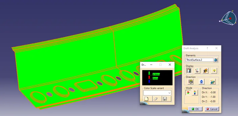
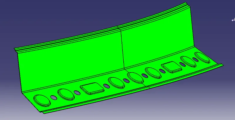
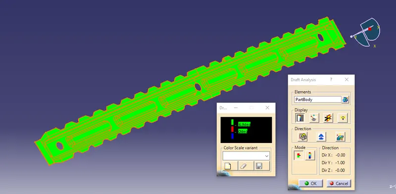
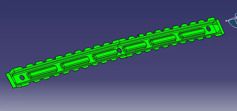
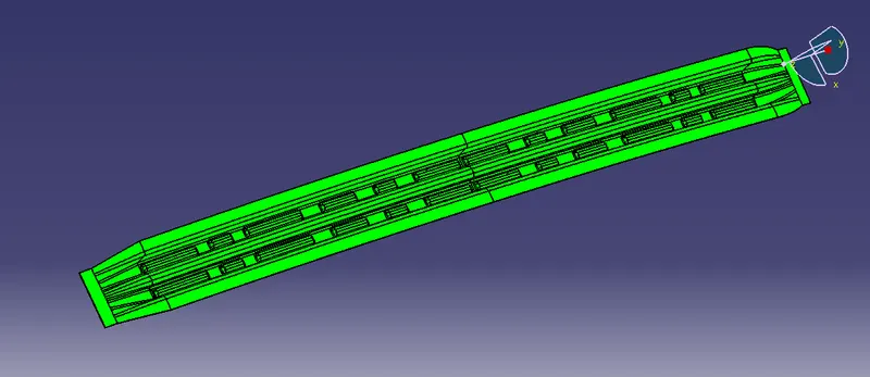
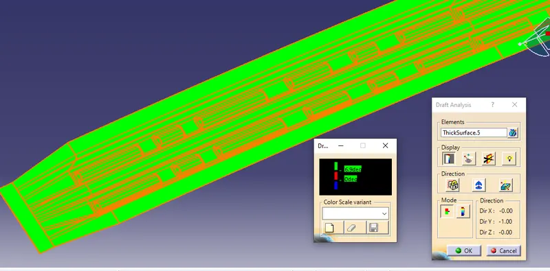
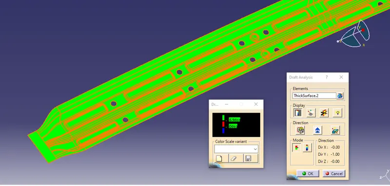
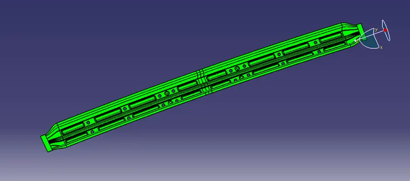
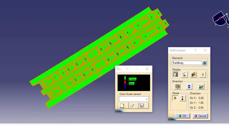
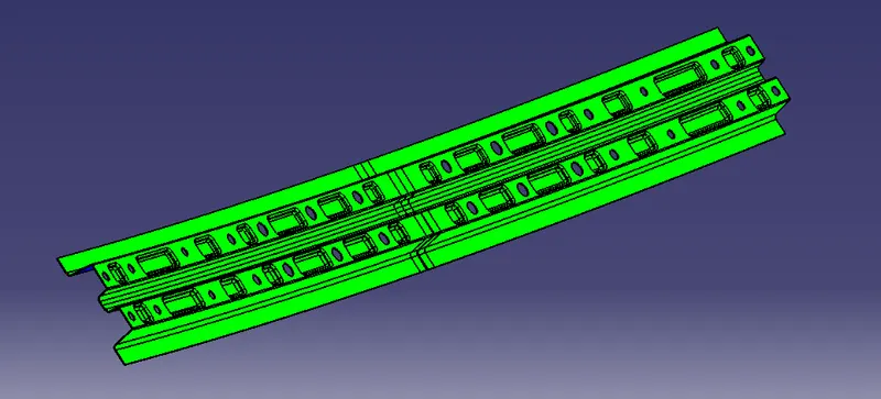
The draft analysis technique is used to analyze whether our part model created in CAD is manufacturable based on the draft condition applied. Here the part should get easily removed from the panel dies (in case of Sheet metal part) or Mold (in case of plastic).
No parts can be ejected from the tool if it is having a straight 90-degree profile from its base surface. A small draft angle is provided to each and every area of the component in order to get easy removal of the component from the tool.
Here we are providing a direction in which components should eject in order to get easy removal of components from the tool. In other words, it also lets us know whether the model is having a draft angle and how much is the draft angle from the tool direction.
FRONT ROOF RAIL
|
|
REAR ROOF RAIL
|
|
BOW ROOF FRONT
|
|
BOW ROOF REAR
|
|
CENTRE REINFORCEMENTl:
|
|
CENTRE ROOF RAIL
|
|
| RESULT |
|
|
CONCLUSION,
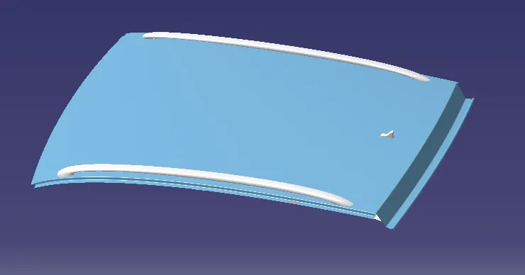
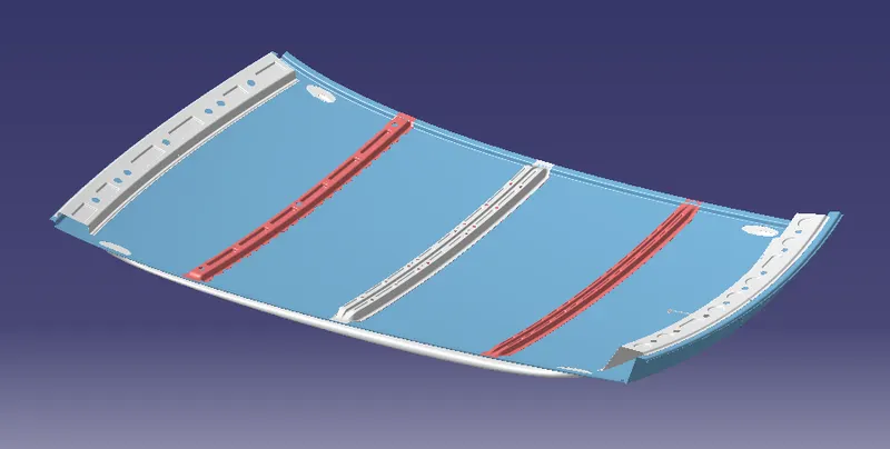
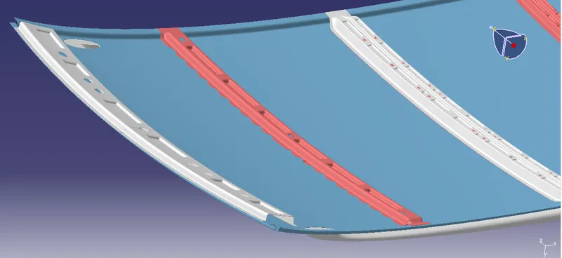
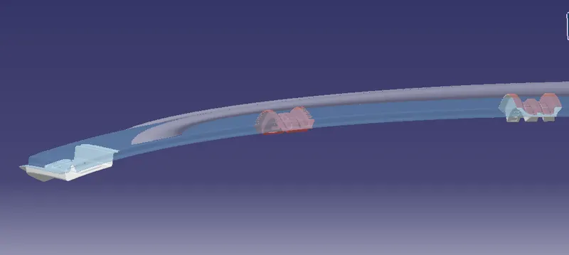
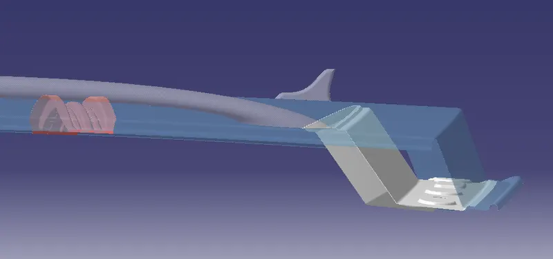
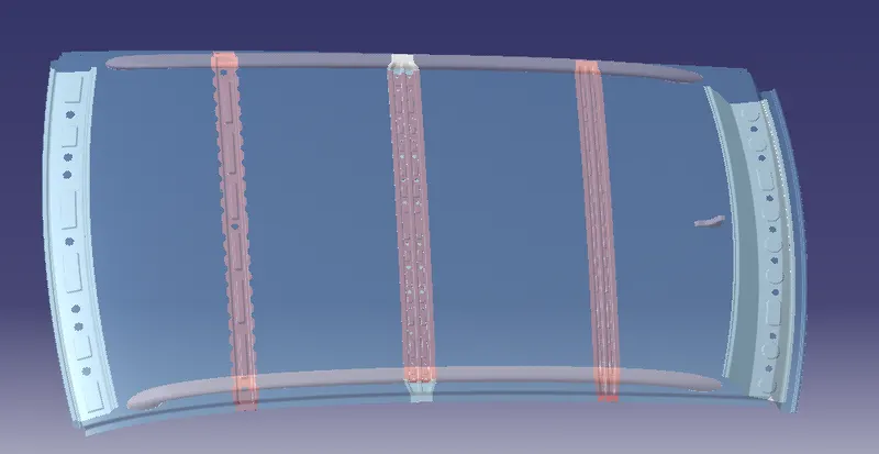
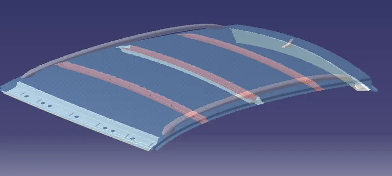
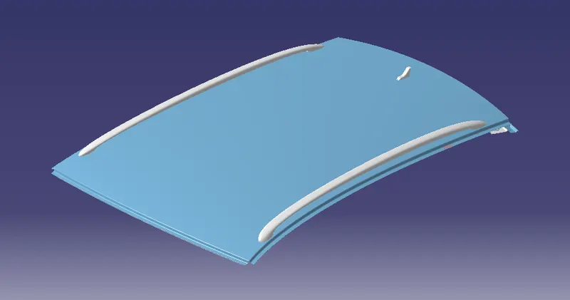
The roof and reinforcement are designed succesfully by following the master section as well as considering the head room and visibility criteria. The draft analysis of designed parts are checked and provided minimum draft angles to all the parts.
Heat distortion and Snow load criteria of design are with in the judgment condition But the value of "s" is outside the limit, So it conclude that better to provide one more bow roof . In addition, embosses are provided to increase the strength of the roof .