Roof Design
ROOF DESIGN & CALCULATION
AIM:
To design & develop the Roof of a car with its components by following the master section and design parameters.
OBJECTIVE: -
- To develop the essential flanges and reinforcements using roof styling as input.
- To do a curvature study on the roof and perform calculations to determine the position of the Bow-roof.
- To determine the Heat Distortion Criteria of the car's roof.
- To find the section modulus on the O-Y section of the roof and for all the components of it.
- To determine the Snow Load Criteria for a car's roof.
- To perform Draft Analysis on the final CAD model of the roof
ROOF DESIGN:
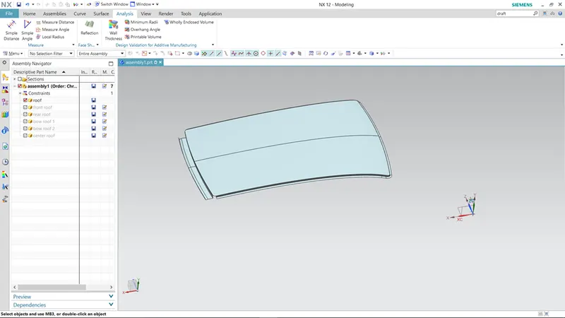
Front Roof Rail: -
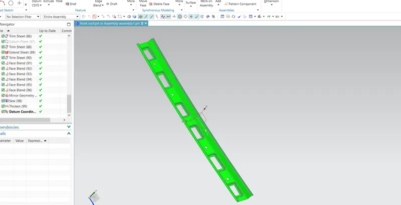
This is the reinforcement provided at the front. This part is joined to the BIW body and windshield. Visibility criteria are considered for joining it with the windshield. It is fixed to BIW with spot welds and the roof surface is attached with the help of mastic sealants. A draft angle is provided for deep-drawing operation. Draft analysis is also done on the section to check its manufacturing ability.
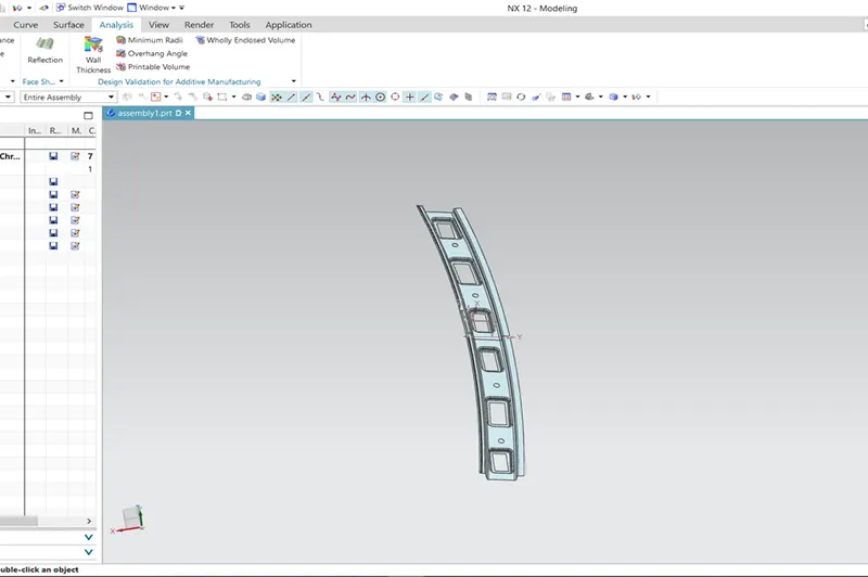
Bow Roof_1: -
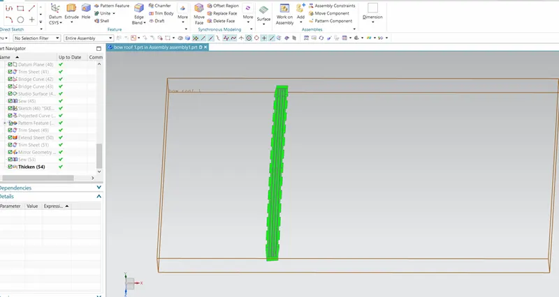
It is an additional reinforcement provided to increase the strength of the roof. It is fixed with a roof body with mastic sealants.
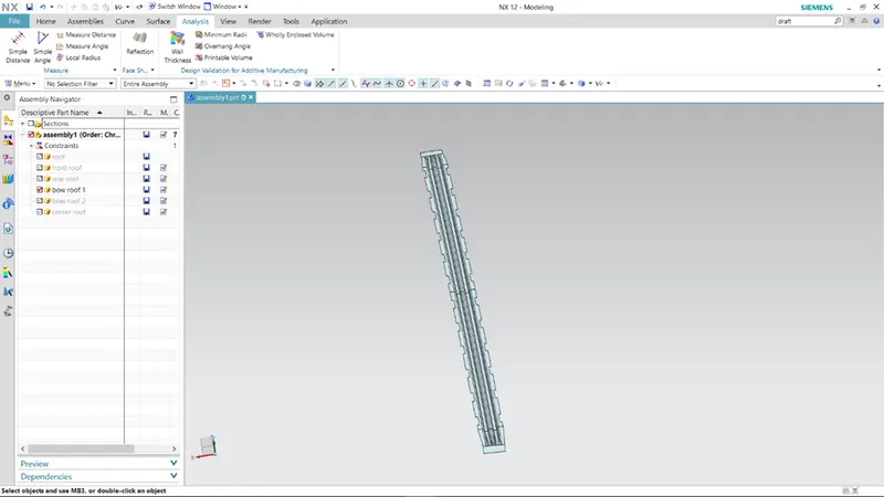
Centre Roof Rail: -
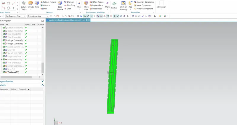
Centre rail roof can be considered as reinforcement joining exact centre to the outer roof. It is fixed to the roof by mastic sealants and BIW by spot welds.
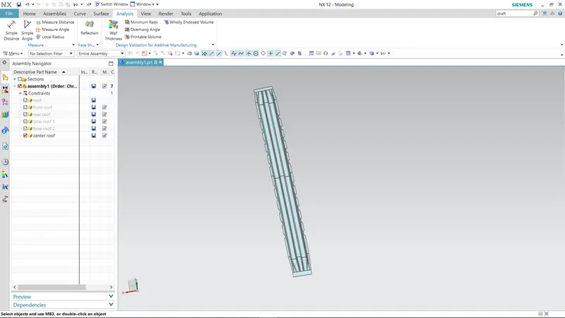
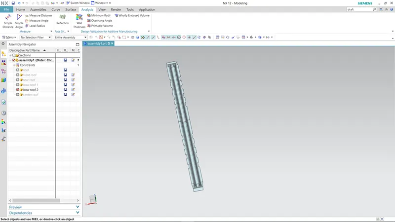
Bow Roof_2: -
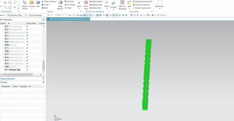
It is like the bow roof_1 provided for better strength.
Rear Roof Rail: -
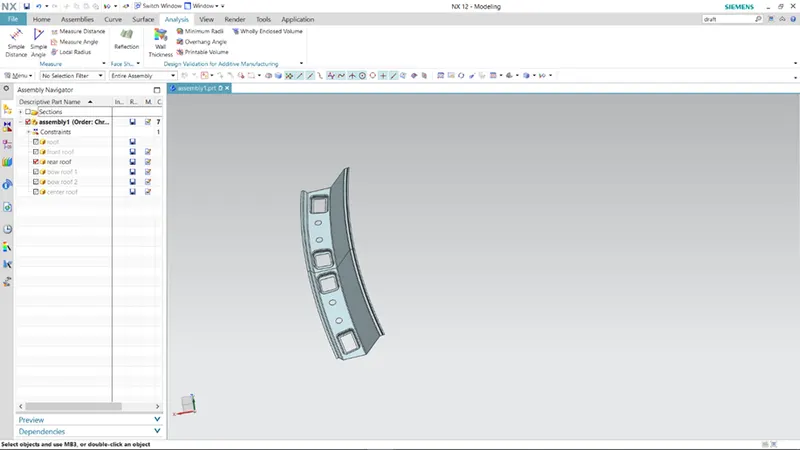
It is the reinforcement provided at the rear side of the roof. Backdoor and body side panels are attached to this part. It is also attached with mastic sealant and spot welds.
HEAT DISTORTION CALCULATION:
The heat distortion study plays an important role in sheet metal usage. Heat distortion temperature is the temperature at which metal softens and deforms under a specified load. While designing roof, this criteria is taken into consideration. We create bow roofs when the roof is long and flat to increase its strength. The position of the bow roofs is to be justified and this justification is done by curvature study:
Heat Distortion Criteria: -
W = [1.73 x 10^(-3) x L] + [1.85 x 10^(-8) x (R^2)/t] + [ 1.10x10^(-3) x l] - 2.68
Condition: OK< 2.7> 3.1
Here,
L = Roof Length in X-Direction[mm] (Roof dimension in 0-Y)
R = Roof curvature
R = 2(Rx*Ry)/(Rx+Ry)
Rx = X curvature
Ry = Y curvature
t = Roof plate thickness [mm]
l = Bow Roof Span [mm]
The thickness of the roof
Roof Outer Panel, t= 0.75 mm
Front Roof Rail, t = 0.75 mm
Rear Roof Rail, t = 0.75 mm
Bow Roof Rail 1, t = 0.75 mm
Centre Roof Rail, t = 0.75 mm
Bow Roof Rail 2, t = 0.75 mm
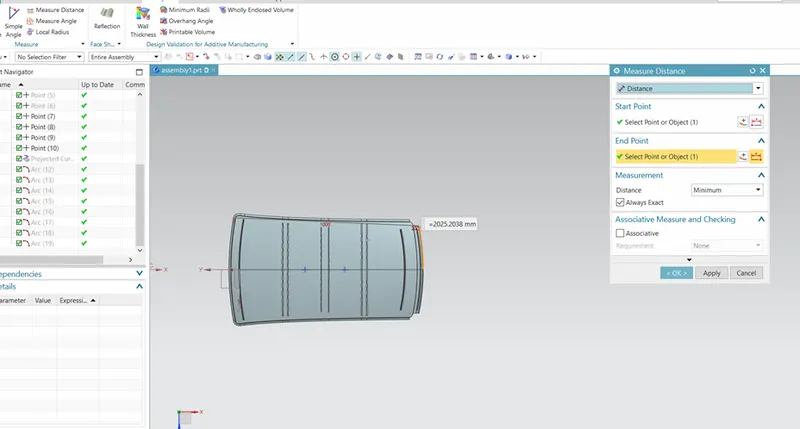
Roof Length for styling surface(L)
For the L we want to take the total length of the styling surface don't include the ditch area as shown below fig,
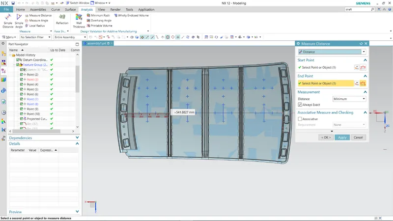
Bow Roof Span(l): -
Here we want to find the distance from the front roof rail to bow roof_1 to find the bow roof span as shown in fig, Similarly, we can measure the remaining span distance also want to measure.
Finding Rx & Ry (X & Y Curvature):-
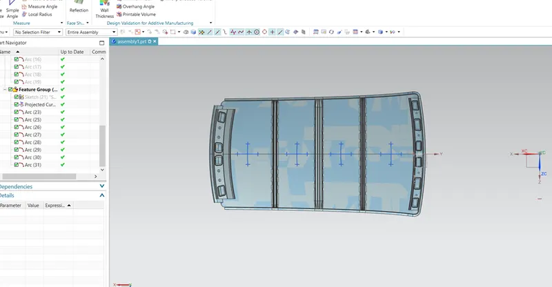
- From the 0-Y axis, at -3Y about the distance of 300 mm is drawn parallel on the perpendicular plane as shown in fig. After that 100 mm lines are offset to either side of the -3Y line. Now center lines are drawn between each adjacent roof rail edge respectively. Intersection points are marked on the sketch and exit the sketch. Make all geometry in construction lines except the points.
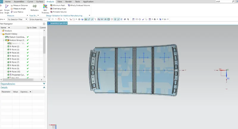
- Project the intersection points in the sketch to roof surface as shown in fig,.
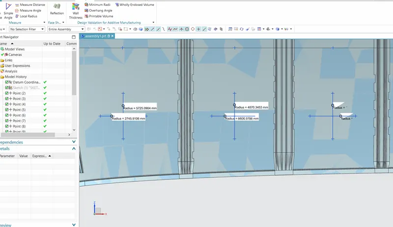
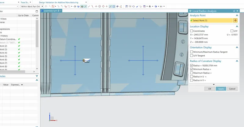
- Join the projected curves as follows & put them into the formula to calculate 'W"
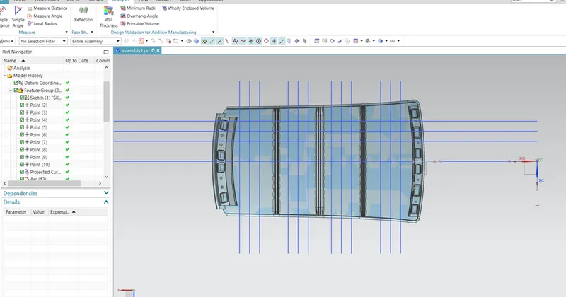
Projects the points and make the arc
Finding the Rx curvature and Ry curvature
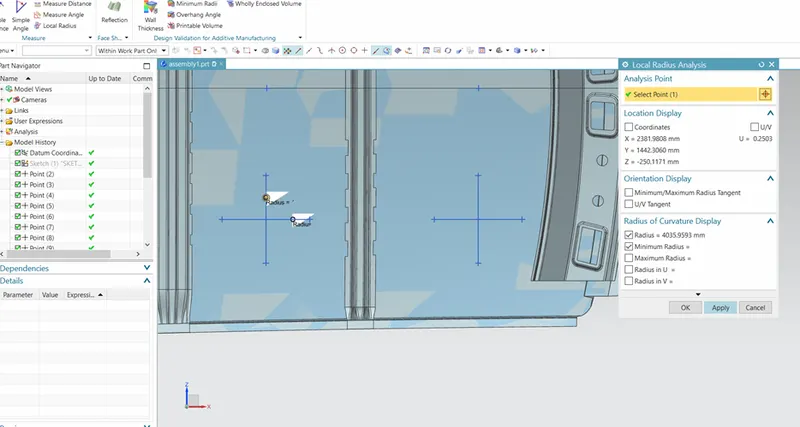
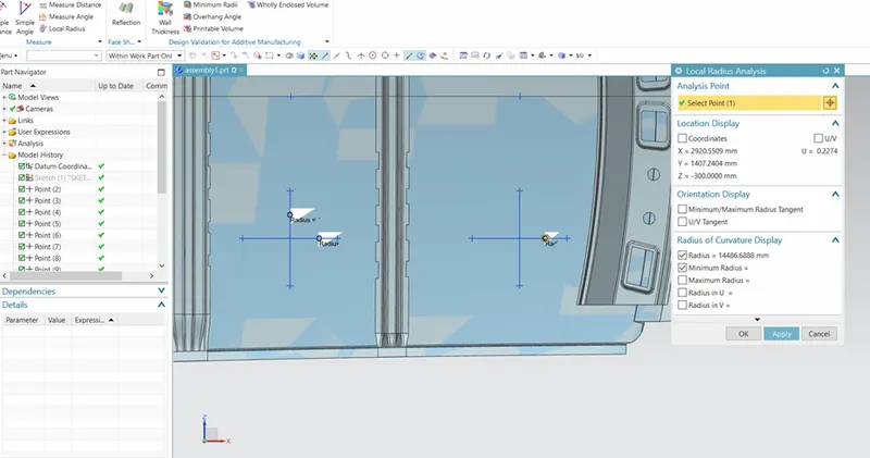
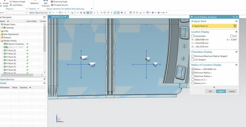
Apply the values in the formula: -
To find the Heat distortion apply all the necessary values from the roof of the given formula.
HEAT DISTORTIONS CRITIRIA CALCULATIONS:
W = [1.73 x 10^(-3) x L] + [1.85 x 10^(-8) x (R^2)/t] + [ 1.10x10^(-3) x l] - 2.68
R = 2(Rx*Ry)/(Rx+Ry)
|
ROOF RAILS |
Rx(mm) |
Ry(mm) |
R(mm) |
L(mm) |
t(mm) |
l(mm) |
W |
Result |
|
FR-BOW1 |
5725.09 |
2745.91 |
3711.6 |
2025.2 |
0.75 |
561.88 |
1.15 |
OK |
|
BOW1- CR |
6606.97 |
4870.34 |
5607.2 |
2025.2 |
0.75 |
432.82 |
1.59 |
OK |
|
CR- BOW2 |
10285.37 |
4035.95 |
5797.12 |
2025.2 |
0.75 |
430.18 |
1.70 |
OK |
|
BOW2-RR |
3295.62 |
14486.68 |
5369.67 |
2025.2 |
0.75 |
541.88 |
1.53 |
OK |
From the above table, it can be concluded that all values of W <2.7 and also not W > 3.1 so thus infer that the current positioning of bow roofs are good in the state as per the design and found OK.
SNOW LOAD PREDICTION:
Snow load prediction study is done to check the durability of the roof to withstand snowfall and reflex back to its original shape without any permanent deformation once the load is removed.
Snow load Prediction formula
Qr = [Iy x t2] / [α x s x [(Rx + Ry)/2]2 x 10-8]
here
α = My x Lx2 x 10-12 , My = Y(Ly-Y)
Judgement condition = Qr ≥ 3.1
250 ≤ s ≤ 380
t = Roof plate thickness [mm]
Ly = Distance between the front and rear roof Rails on the Vehicle along with 0Y[mm]
Length of Roof panel with the center point between Roof rail Front /Rear as the front and rear reference point.
Lx = Distance between the Left and Right end of the roof on the Roof BOW [mm]
The width of the roof panel is exposed on the surface.
Y = Distance front Front Roof Rail to Roof BOW[mm]
s = Distance for which Roof BOW bears divided load [mm]
s = L1/2 + L2/2
Iy = Geometrical moment of inertia of Roof BOW (Y cross-section )[mm4]
Rx = Lateral direction curvature radius of roof panel Y cross-section on Roof BOW [mm]
Roof panel curvature Radius of the Length Lx in Front view
Ry = Longitudinal Direction curvature radius of the Roof panel X cross-section on Roof BOW [mm]
Roof panel X curvature radius of length s in Side view
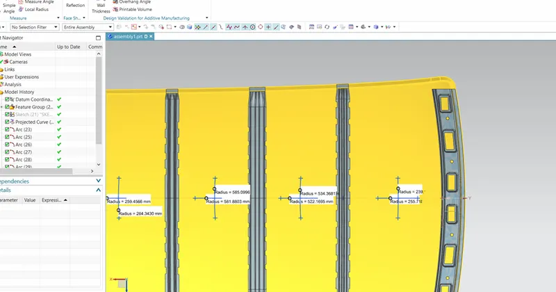
To measure the Rx & Ry (X & Y curvature)
Previously we calculate the Rx & Ry in heat distortion criteria at this time we calculate the values at the center of the roof as shown below fig,
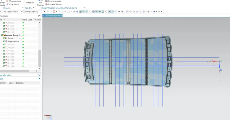
Find the Rx Curvature and Ry Curvature
After measuring the Rx and Ry values,
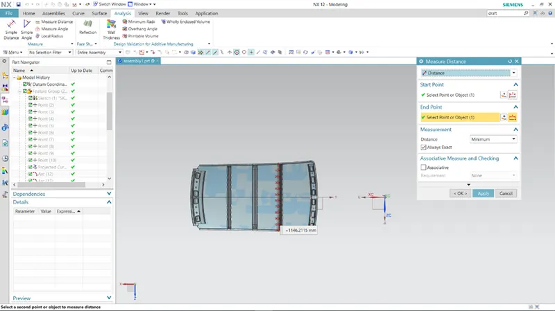
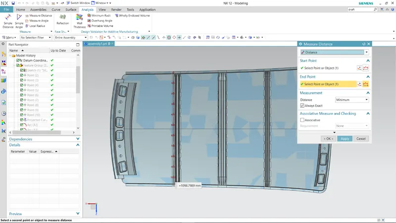
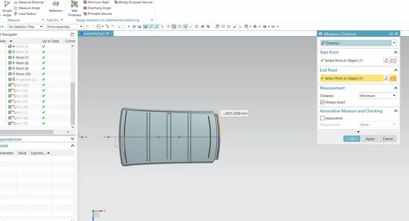
- To find the Lx & Ly values take the styling surface of the roof.
LX VALUES:
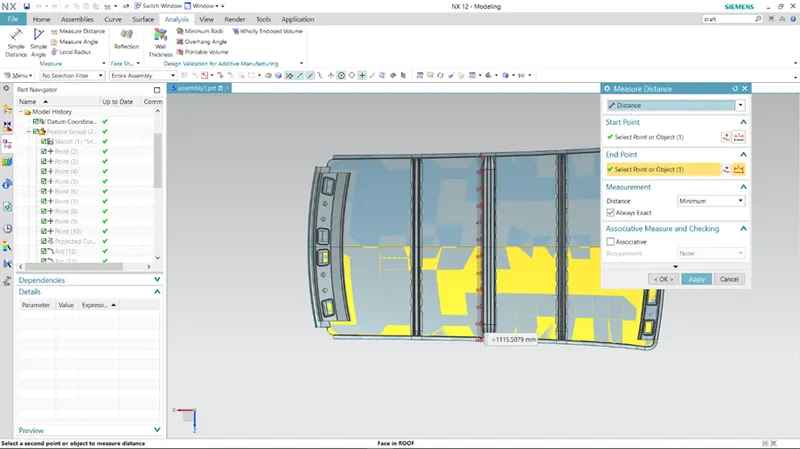
LY VALUE:
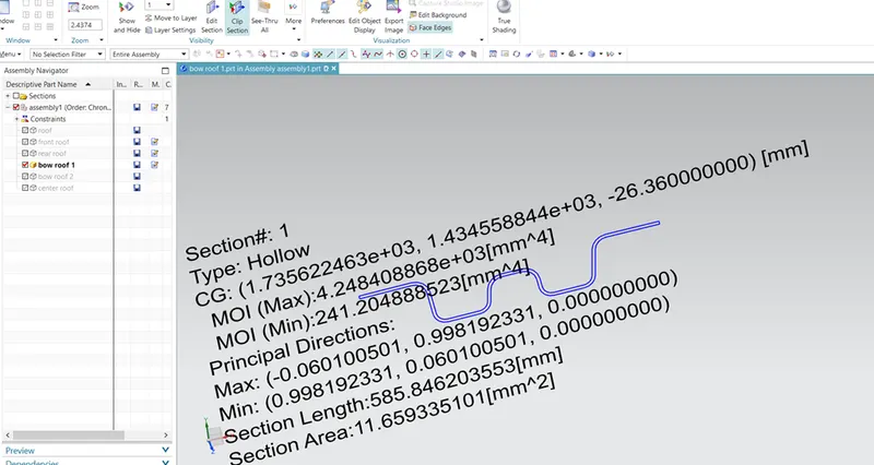
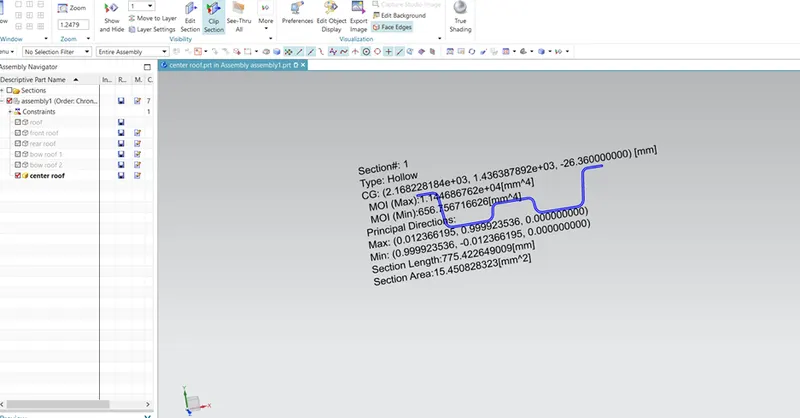
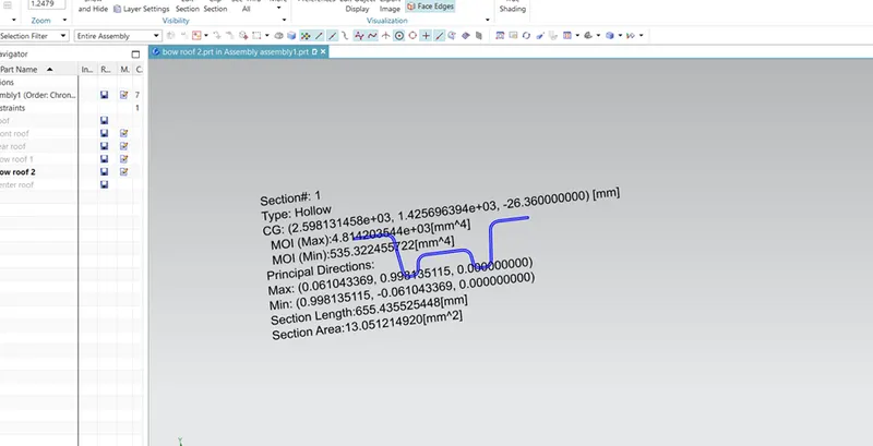
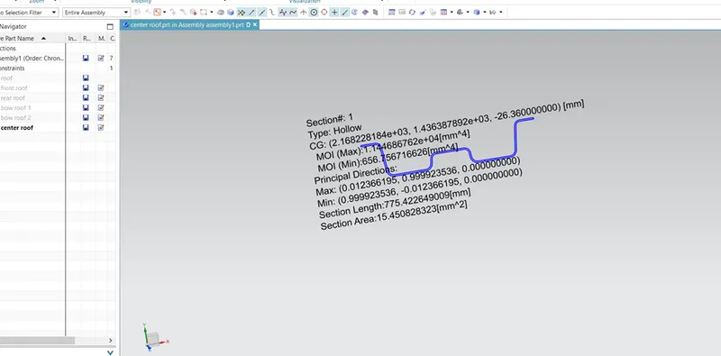
Moment of Inertia for the roof rails:
BOW ROOF 1:
CENTRE ROOF :
BOW ROOF 2:
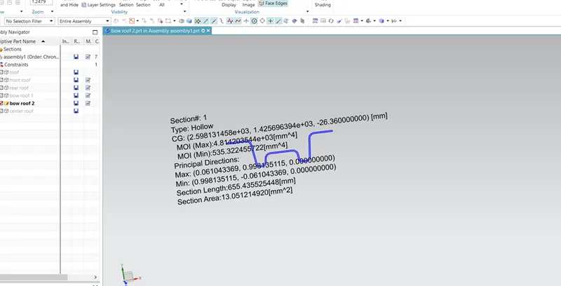
Apply the values in the formula: To find the snow load applies all the necessary values from the roof to the given formula.
Qr = [Iy x t2] / [α x s x [(Rx + Ry)/2]2 x 10-8]
Where
α = My x Lx2 x 10-12 , My = Y(Ly-Y)
s = (L1+L2)/2
SNOW LOAD CRITERIA CALCULATION
|
Roof Rails |
Iy(mm) |
Lx(mm) |
Ly(mm) |
L1(mm) |
L2(mm) |
Rx(mm) |
Ry(mm) |
t(mm) |
Y(mm) |
S |
My |
α |
Qr |
Result |
|
FR-BOW_1 |
241.2 |
1146.2 |
2025.2 |
352.7 |
450.3 |
255.7 |
239.1 |
0.75 |
352.7 |
401.5 |
589890.75 |
0.774 |
5.13 |
OK |
|
BOW_1-CR |
656.7 |
1115.5 |
2025.2 |
350.1 |
352.7 |
522.1 |
534.3 |
0.75 |
350.1 |
351.4 |
586452.5 |
0.73 |
4.28 |
OK |
|
CR-BOW_2 |
535.3 |
1098.7 |
2025.2 |
396.0 |
350.1 |
585.0 |
581.8 |
0.75 |
396.0 |
373.0 |
645163.2 |
0.75 |
3.56 |
OK |
It is observed from the values that obtained values of Qr > 3.1
THUS, ALL THREE ROOFS SATISFY THE SNOW LOAD CONDITION
Section Modulus:
Section modulus is a geometrical property for a given cross-section used on the design of beams or flexural members. Other geometrical properties used in the design include an area for tension and shear, the radius of gyration for compression, the moment of inertia, and the polar moment of inertia for stiffness. Any relationship between these properties is highly dependent on the shape. There are two types of section modules.
- Elastic section modulus
- Plastic section modulus
the elastic section modulus is defined as,
S=I/Y
S= section modulus
I= moment of inertia
Y is the distance between the neutral axis to the most extreme fiber.
FRONT ROOF RAIL:
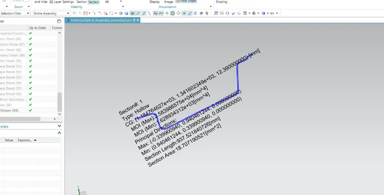
Moment Of Inertia (Max), Imax= 258.39*10^2(mm^4)
Moment Of Inertia (Min), I min= 1628.9(mm^4)
Section modulus, S = I/Y,
Y= 63.4mm
by using these values, we can find the section modulus (S)
For maximum, S = 258.39*10^2/ 63.4
= 407.5mm^3
For minimum, S = 1628.9(mm^4)/ 63.4
= 25.69mm^3
REAR ROOF RAIL:
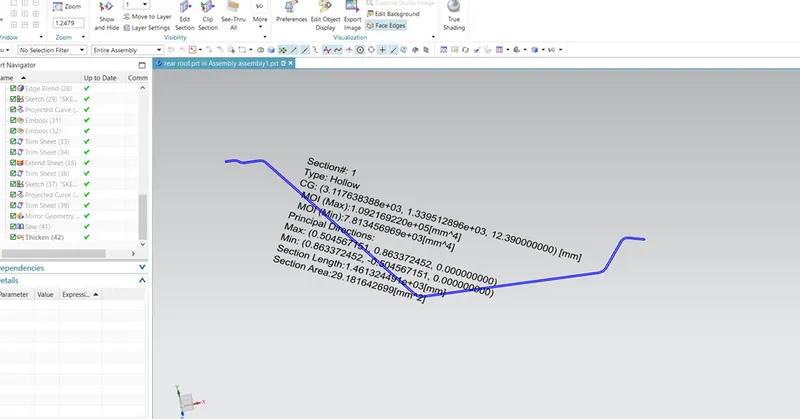
Moment of inertia (max) Imax= 10.921*10^4[mm^4]
Moment of inertia (min) I min = 7813.4mm^4]
Section modulus (S)= I/Y
Smax = 1722.5 mm^3
S min= 123.2mm^3
similarly, we can calculate the section modulus, bow roof_1, centre roof rail, bow roof_2
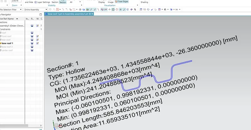
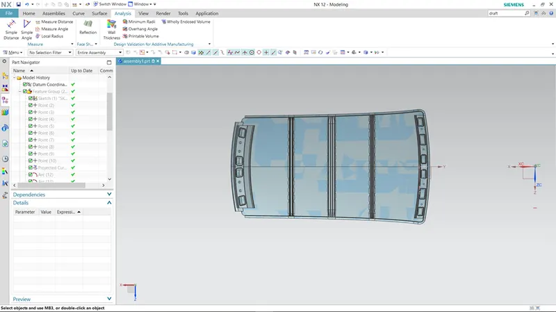
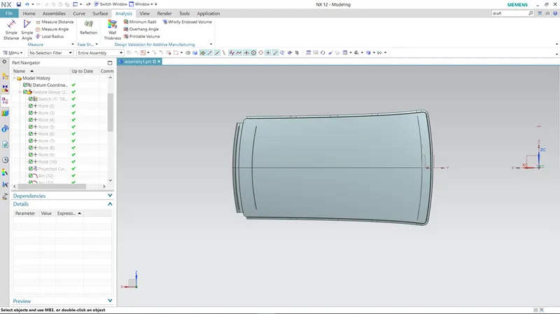
ROOF MODEL VIEWS
DRAFT ANALYSIS:
FRONT ROOF:
BOW ROOF 1:
CENTRE ROOF:
BOW ROOF 2:
REAR ROOF:
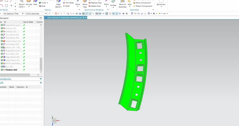
ROOF:
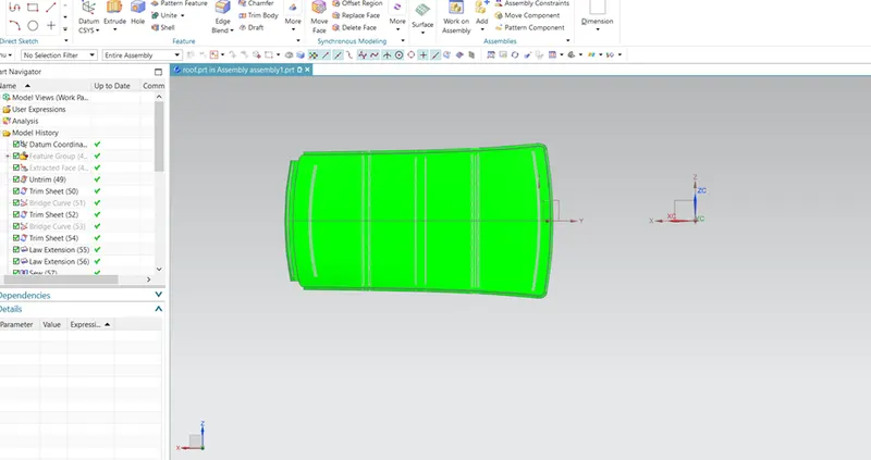
CONCLUSION:
The design of the roof, front roof rail, rear roof rail, bow roof1, bow roof2, centre roof rails by following the master section with the design parameters for the given class A surface is done.
- All reinforcement of the roof is designed according to the input data.
- Made the curvature study and analysed the design for snow load and were found ok.
- Moment of inertia, section modulus, and Draft analysis is carried out the check the feasibility of manufacturing is found Ok.